Disassembly of 9V LiIon batteries
I have reviewed these two batteries and wanted to see how the electronic was made. One is only a protection circuit, the other is a usb charge circuit and a boost converter.
iPowerUS
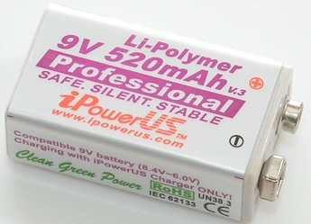
This replaces a normal 9V rechargeable battery.
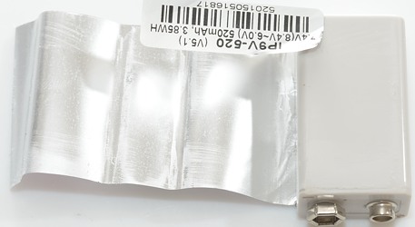
First step is to get rid of the wrapper, the wrapper is made of multiple pieces.
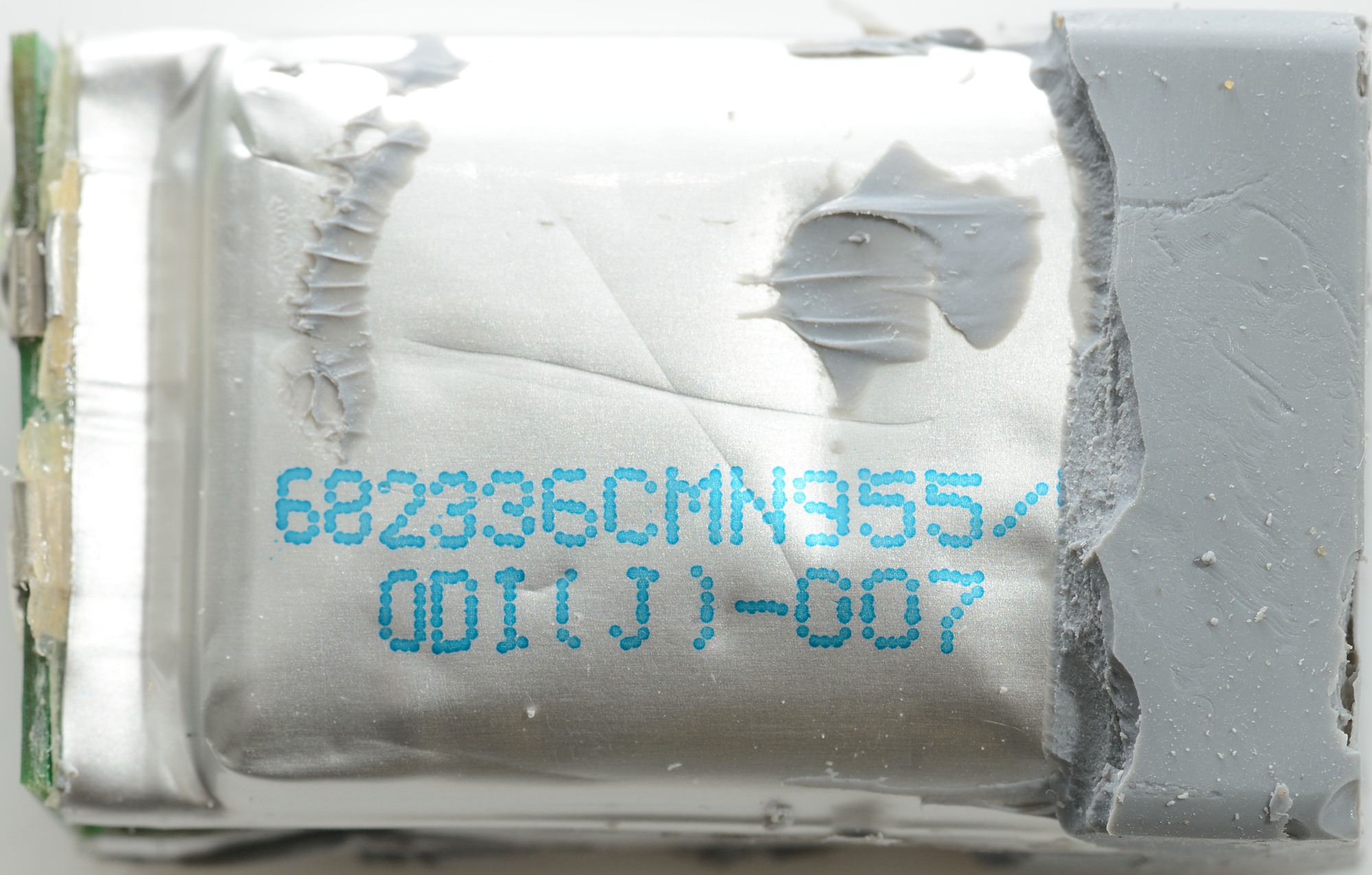
To open the cell I had to cut the top off, it was glued (or maybe welded) together.
The protection circuit is below a piece of isolation paper.
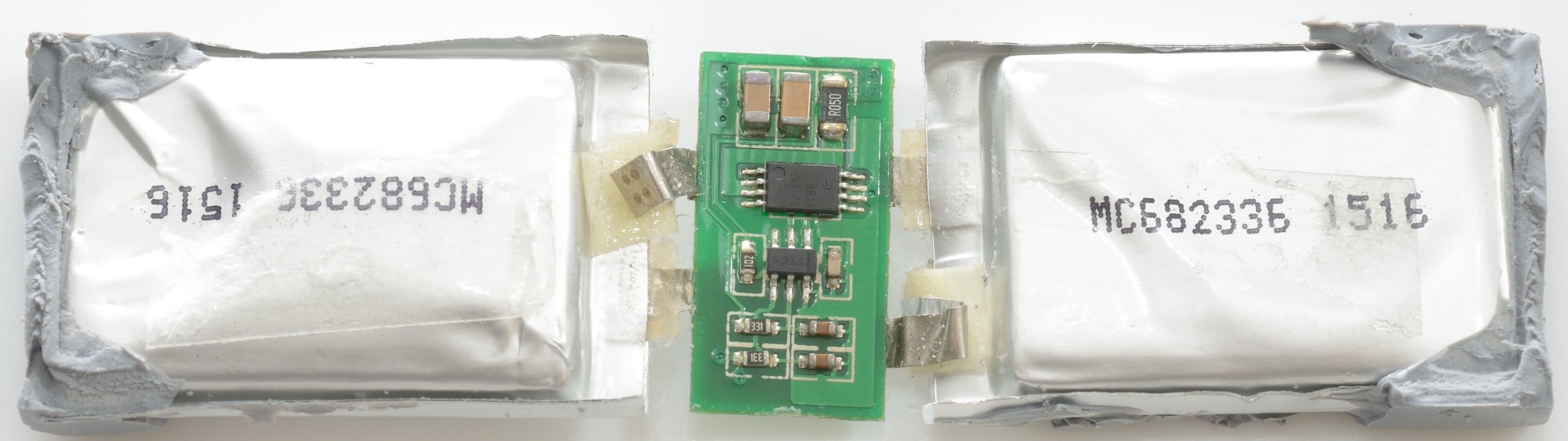
I could not get the cells or the circuit out, I had to cut the battery open. It is easy to see why the cells would not come out, the gray stuff is keeping them in place.
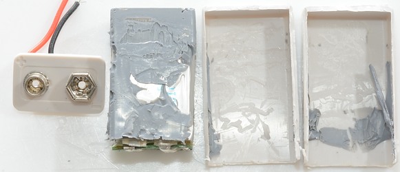
It was difficult to remove all the gray stuff and when the cell started to inflate I decided to stop (Not really a indoor job).
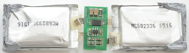
The two cells are connected in series with the protection circuit between.
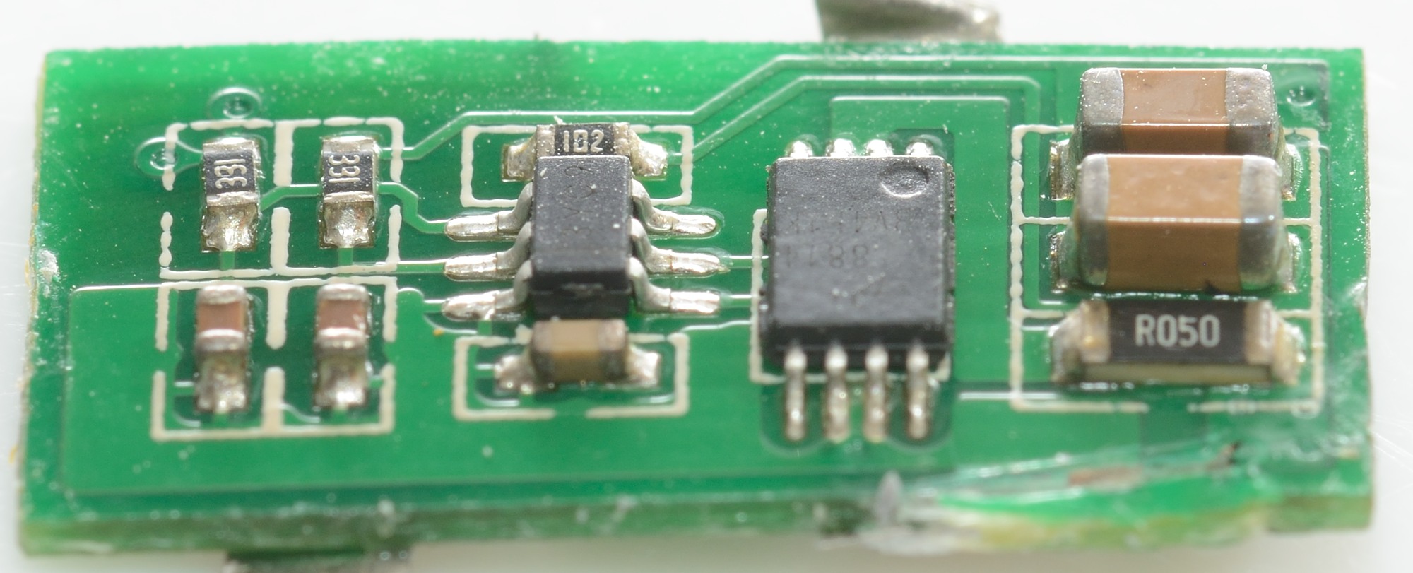
The two chips on it are:
3YC9: Dual LiIon protection.
3V451K: Dual mosfet.
Usual protection circuits uses the resistance in the mosfet, but in this case here an external resistor is added (The overload current is fairly low for this type battery).
It do not look like there is any balancing between the two cells.
Znter
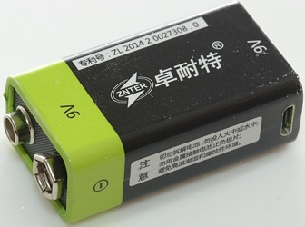
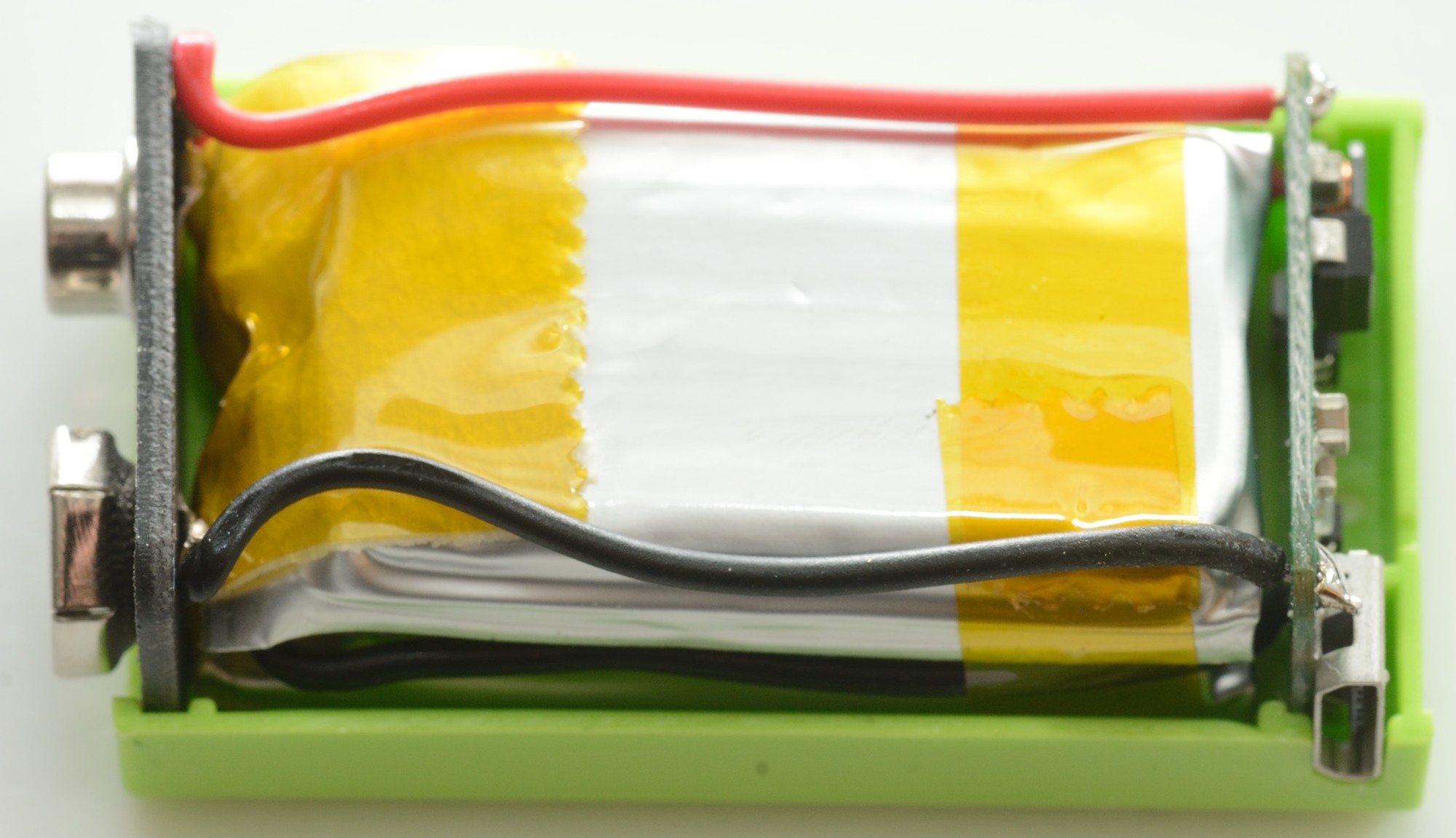
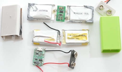
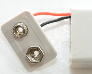
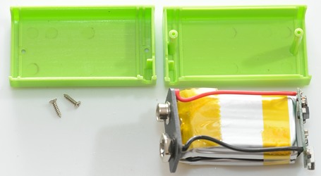
This is the usb charged battery.
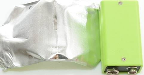
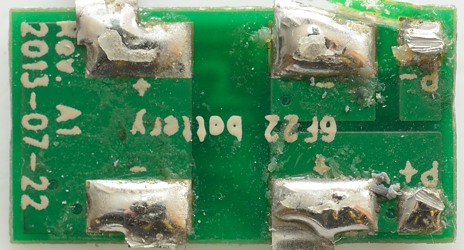
The wrapper is only one piece and there is screws, making it easy to disassemble.
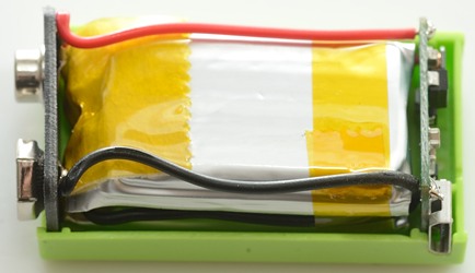

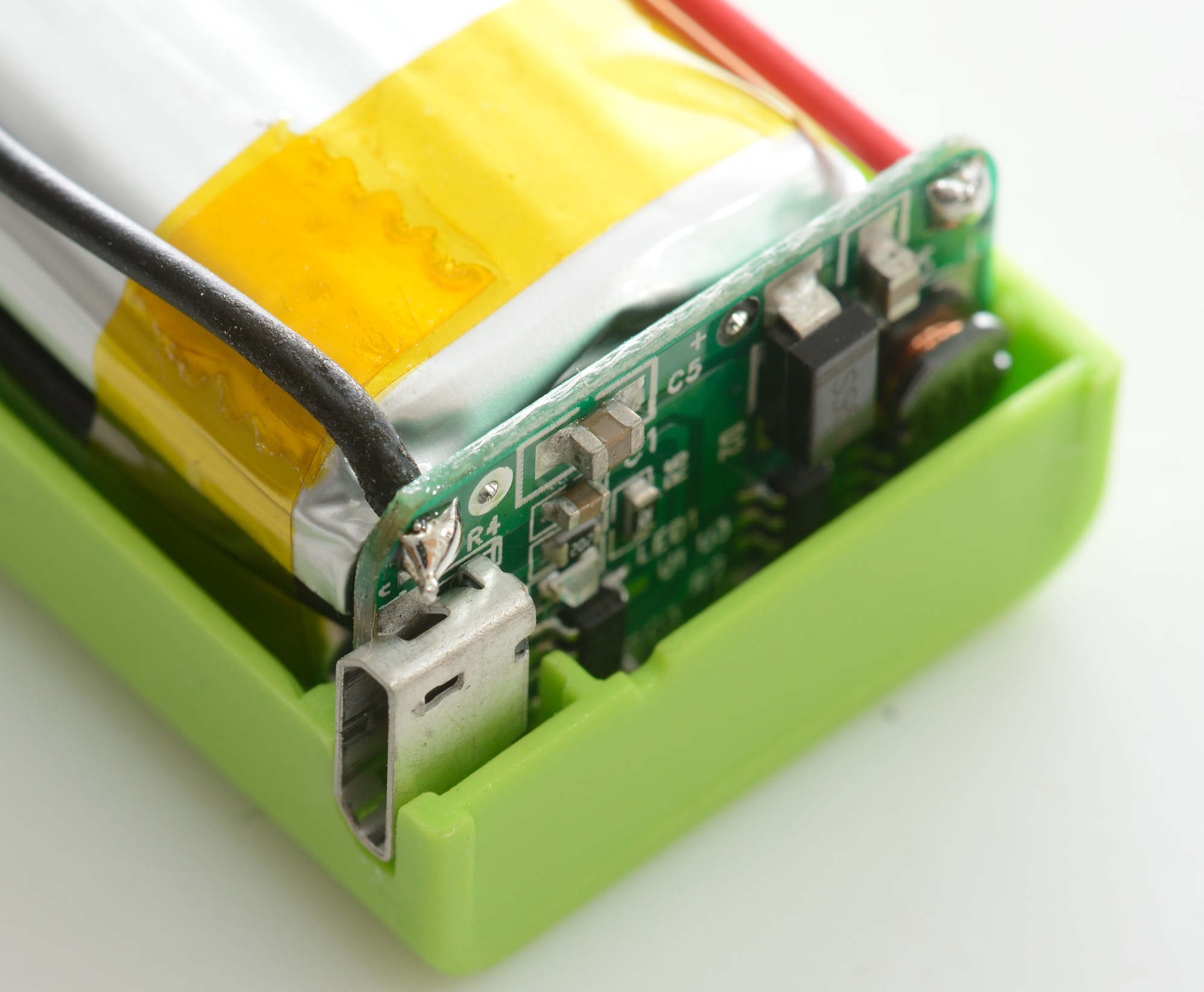
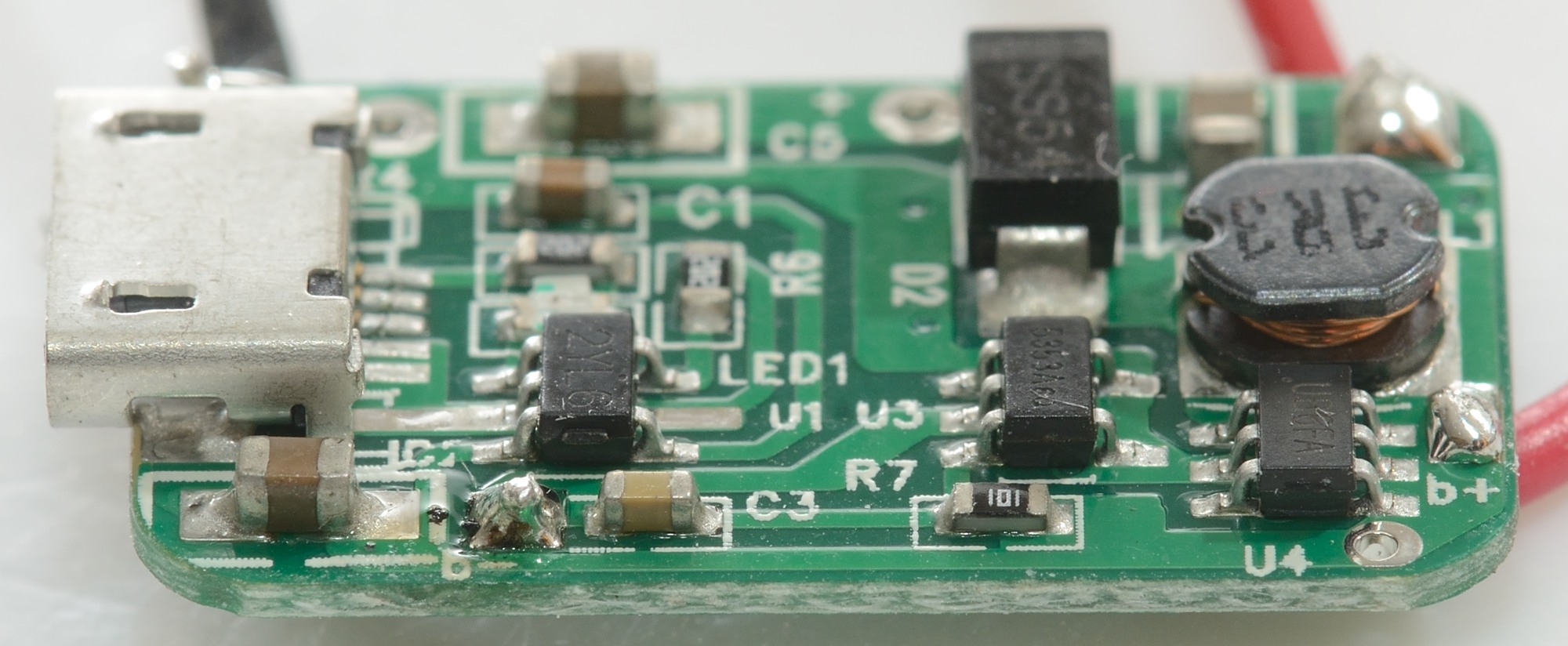
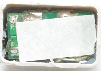
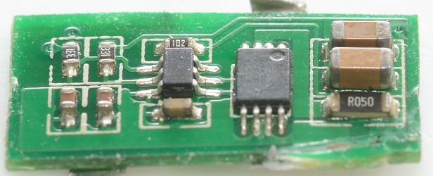
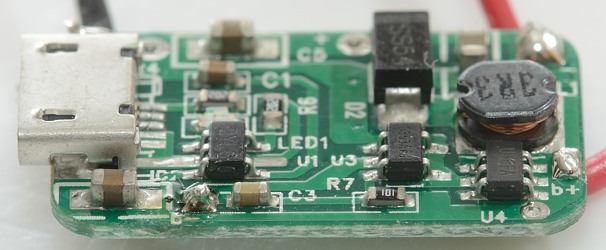
The usb charge circuit and boost converter is placed at the bottom of the battery.
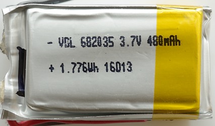
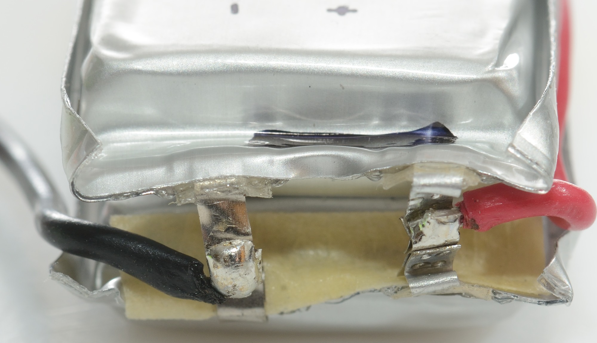
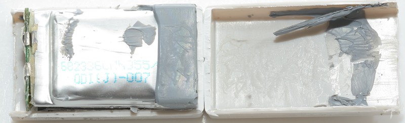
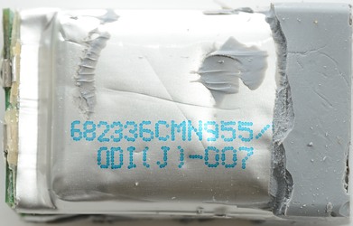
There is two pouch cells in the battery, each rated at 480mAh.

The cells are connected in parallel and has wires to the circuit board. The parallel connection means there is no need for balancing.
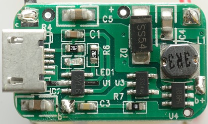
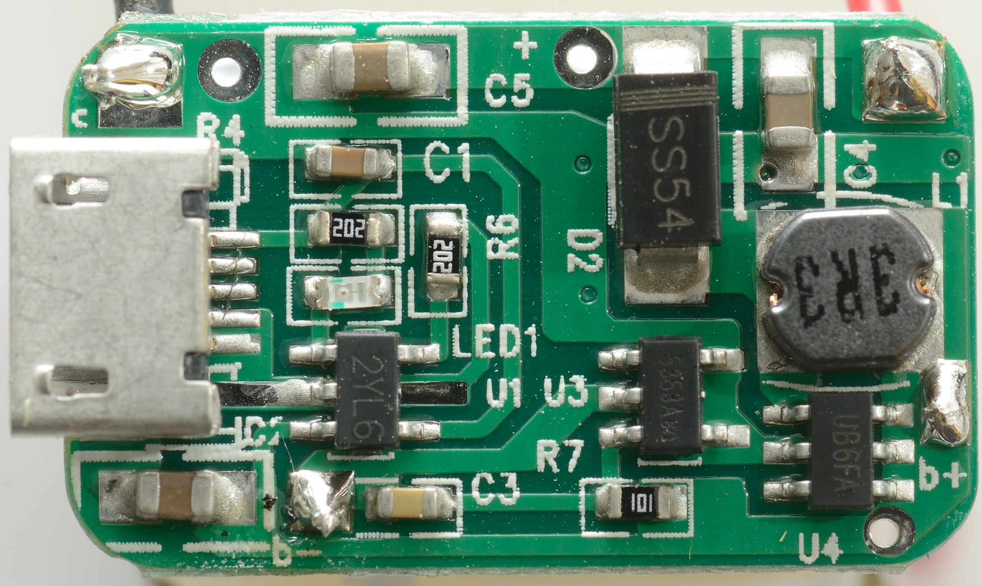
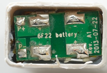
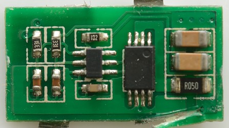
There is 3 chips on the circuit board:
2YL6: Independent linear lithium battery charger
5353A: Battery protection IC
UB6FA: Boost converter
The battery is connected at b+ and b- at the bottom, output terminals are at the top.
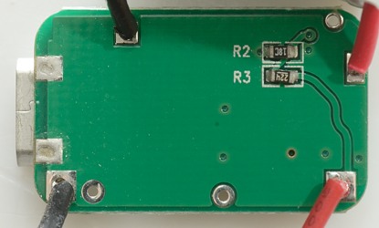
The two resistors on this side controls the output voltage.
Conclusion
It is interesting to see the two solution. There are many differences in how the cells works and can be used:
- The iPowerUS has space for slightly larger cells
- The iPowerUS can deliver most energy, because there is no looses in a boost converter.
- The iPowerUS will deliver most mAh due to the lower voltage.
- The iPowerUS has a fairly low output voltage.
- The iPowerUS can be charged on a normal NiMH charger, the protection circuit will protect the battery (This is not ideal, but will work).
- The iPowerUS required a special LiIon charge for best performance.
- The iPowerUS is very good at low power applications, because LiIon can maintain charge for a long time.
- The iPowerUS may work with a battery gauge.
- The iPowerUS may die before the cells are worn down due to voltage difference between the two cells.
- The Znter has highest output voltage (Like a new Alkaline battery).
- The Znter can be charged correctly with any usb charger.
- The Znter is not very good at low power applications, due to the boost converter draining the battery.
- The Znter will prevent any battery gauge from working.
- The Znter will work until the cells are worn down.
Notes
iPowerUS review Zenter Review