Building a high current adapter
When measuring current the voltage drop in the measuring circuit can be a problem, but there are a couple of ways around that:
- Using a current clamp. This solution is very good when measuring more than a couple of amps.
- Using a small resistor. This is also a good solution, but it is necessary to measure some low voltages and there will be galvanic connection between the meter and circuit (Only a problem with oscilloscopes and some logging equipment).
- Using a special current measuring chip. These chips uses the same principle as the current clamp, but everything is on a single chip.
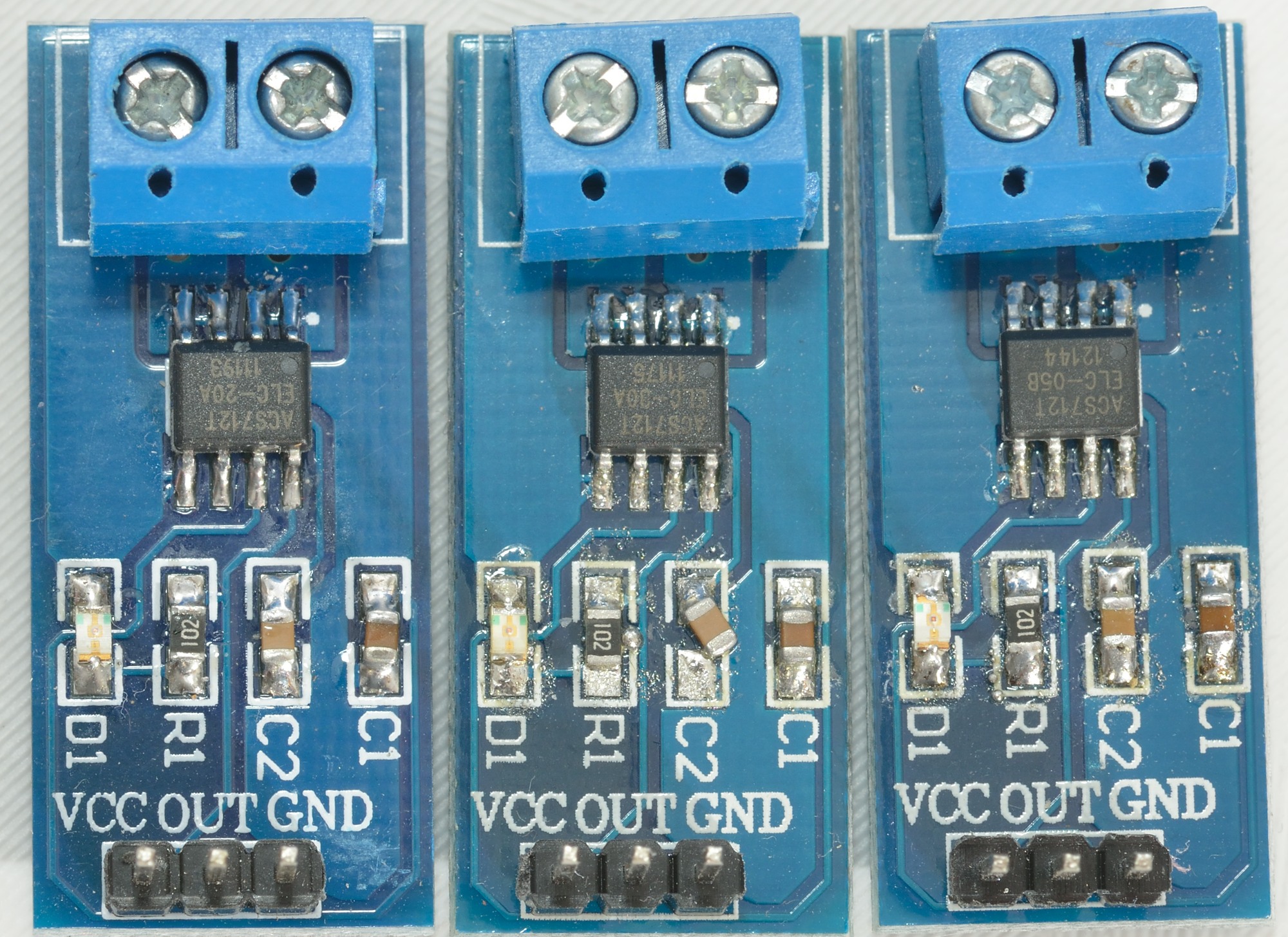
I will be looking at the chip solution here and build a small adapter with the chip (The chip is called ACS712).
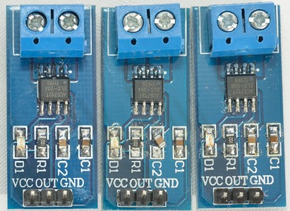
The chip exist in 3 version, a 5A, a 20A and a 30A, here I have bought all 3 version, mounted on some small PCB's, this way I can use them without designing my own PCB.
A look at the datasheet, gives some information about the chip:
- 5A chip: 0.185 V/A
- 20A chip: 0.100 V/A, I will be using this, due to the easy calculations.
- 30A chip: 0.066 V/A
This means that the 20A chip will output 1V, when the current is 10A, that is easy to measure with any DMM.
But the voltage is not from 0 volt, it is from half the supply voltage, i.e. when the chip is supplied with 5 volt and the current is zero, the output is 2.5 volt and the 1 volt output from a 10A current is added or subtracted from the 2.5 volt, i.e. depending on current direction the output voltage will be 1.5 or 3.5 volt at 10A.
The chip has 1.2 mOhm resistance in the current path, i.e. at 20 ampere it will only drop 0.024 volt. When mounted on a PCB and with connection, the final resistance will be considerable higher.
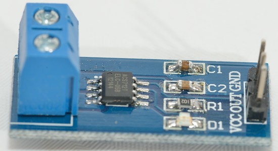
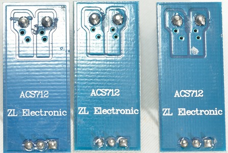
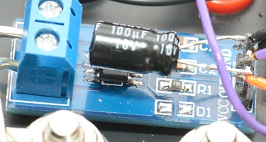
A look from the side.
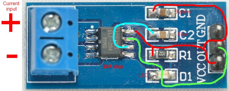
On this picture I have marked the + PCB trace in red, the signal trace in green and a filter signal in cyan.
When current goes into the + input, the output voltage will rise.
The led is on when power is connected.
The circuit draws 13 mA with the led, it is about 10 mA for the chip and 3 mA for the led.
Building
To build the adapter I need some sort of power supply, with only 13mA current draw a battery must be fine. Because the chip needs 5 volt and preferable very stable I also need a voltage regulator. With a battery I want a low power and low dropout regulator. Looking around in my different component boxes I found some LM2931A, this regulator chip uses only a few uA and will deliver 5 volt output down to about 5.1 volt input. It does also have polarity protection, i.e. if I insert the battery the wrong way around, it will just block the current.
With a 9 volt E block I will get about 600mAh/13mA -> 46 hours runtime, more than enough for doing regular measurements, but not very good if I want to be logging for days.
To see when the battery is empty, I will also need a led. In series with this led I have added a zenerdiode to make it turn off (or rather go very weak) at around 5 volt.
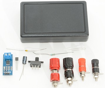
The above picture shows all the parts.
- The current adapter chip/pcb.
- White led
- 3.3 kohm resistor for led
- 4.1 volt zener for led
- LM2931A 5 volt regulator
- 100uF/10V capacitor for regulator.
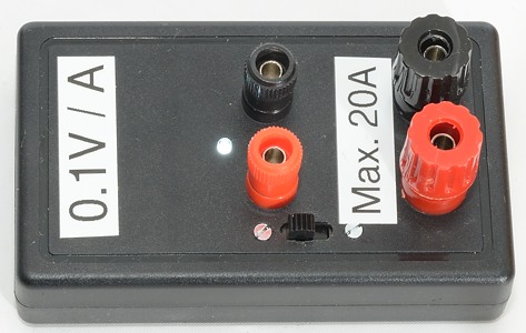
- 2 x 30A binding posts.
- 2 x binding posts.
- A on/off switch.
- A box, with room for a 9V battery.
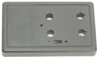
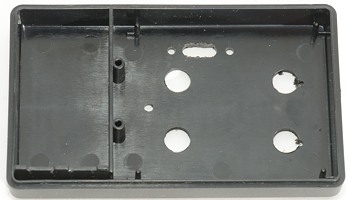
First I need some holes in the box.
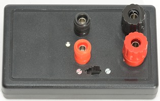
The switch, led and binding posts are mounted on the box.
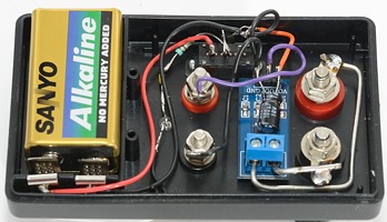
The components mounted. I have used some rather thick copper wire between the binding posts and the adapter pcb.
The regulator is mounted directly on the switch.
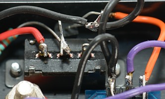
I have removed the led (D1), to save some power.
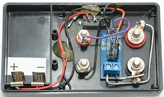
After testing I have added some hot melt glue to the critical points.

A few labels on the front of the box.
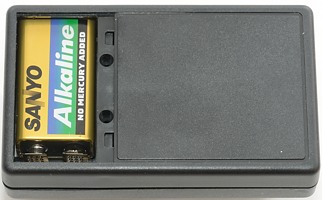
The box has a separate cover for the battery, i.e. I do not need to open the box for battery replacement.
General specifications
The final box uses 11mA, 10 for the chip and 1 the led. This will give an estimated runtime of 600/11 -> 54 hours or a bit above 2 days.
The 600mA in a 9 volt battery is from the Energizer datasheet for low current (10mA) discharge to 6 volt.
As can be seen in the tests below I got about 6 mOhm resistance in the circuit or 19 mOhm with test wires connected. I could have reduced the 6 mOhm by removing the terminals on the PCB and soldering the wires directly to the PCB. I could also use shorter test wires and screw them directly into the binding post, that would also reduce the resistance.
6 mOhm is 0.12 volt drop at 20A
19 mOhm is 0.38 volt drop at 20A
The Fluke 189 DMM has 59 mOhm with test wires, that is 1.2 volt at 20A (Note: DMM is 10A max.).
The galvanic isolation, there is no connection between the current input terminals and the DMM output terminals.
What DMM to use
Because the output voltage is in the range 0.5 to 4.5 volt, the best DMM must have a 5000 or 50000 count display. A 3000 or 4000 count will also work fine but will not have full resolution over the full range.
Depending on the DMM the resolution will be:
- 2000 count DMM -> 0.1A
- 3000-4000 count DMM -> 0.01A at some currents.
- 5000 count DMM -> 0.01A at the full range.
- 30000-40000 count DMM -> 0.001A at some currents.
- 50000 count DMM -> 0.001A at the full range.
With a careful zeroing of the DMM, it is possible to get a actual precision of about +/-2 mA when measuring low currents. This means that a reading of 20mA would mean the actual current is between 18 and 22 mA. This is much better than a typical clamp meter.
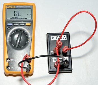
Testing with power supply
For the first test I have made a setup with a couple of DMM's and a power supply. In this test the adapter and the DMM is supposed to show exactly the same current, because they are in series.

Everything connected and power is on.
Fluke 179 is measuring the voltage drop in the adapter.
Agilent U1272A is measuring the output from the adapter/chip.
Fluke 189 is measuring the current.
The output from the chip is 2.5163 volt.
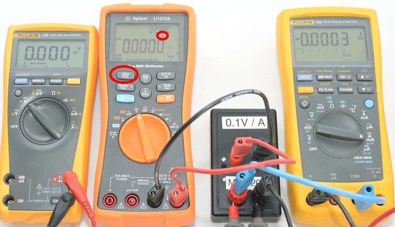
Lets get rid of the 2.5xx volt. With most DMM's is is possible to use a REL button, that will show difference from when the button was pressed. This is a case where it is very useful.
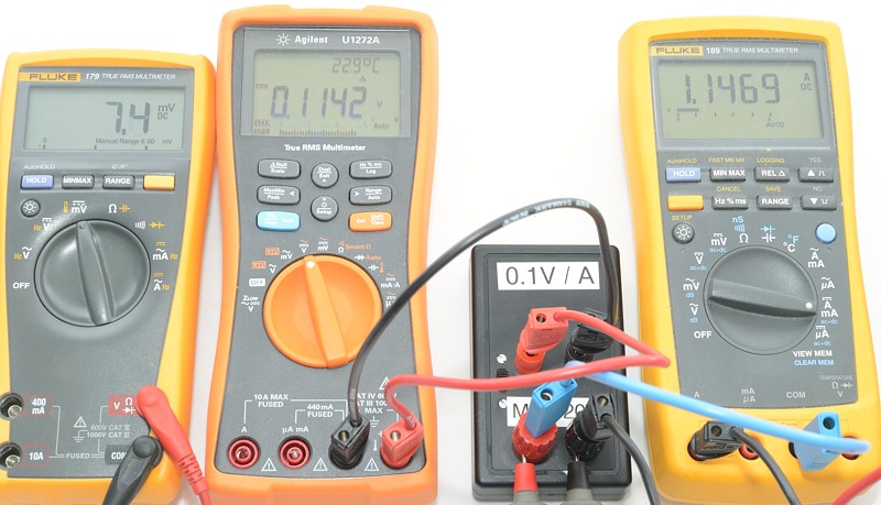
First test with about 1A.
Fluke 189: 1.1469A
Agilent U1272A: 0.1142V -> 1.142A, difference from above is about 0.4%
Fluke 179: 7.4 mV in voltage drop, i.e. 6.4 mOhm resistance
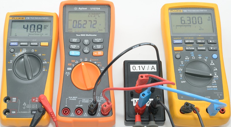
Test with about 6A.
Fluke 189: 6.300A
Agilent U1272A: 0.6272V -> 6.272A, difference from above is about 0.4%
Fluke 179: 40.8 mV in voltage drop, i.e. 6.5 mOhm resistance
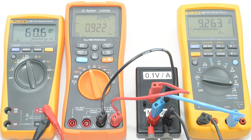
Test with about 9A.
Fluke 189: 9.263A
Agilent U1272A: 0.922V -> 9.22A, difference from above is about 0.5%
Fluke 179: 60.6 mV in voltage drop, i.e. 6.5 mOhm resistance
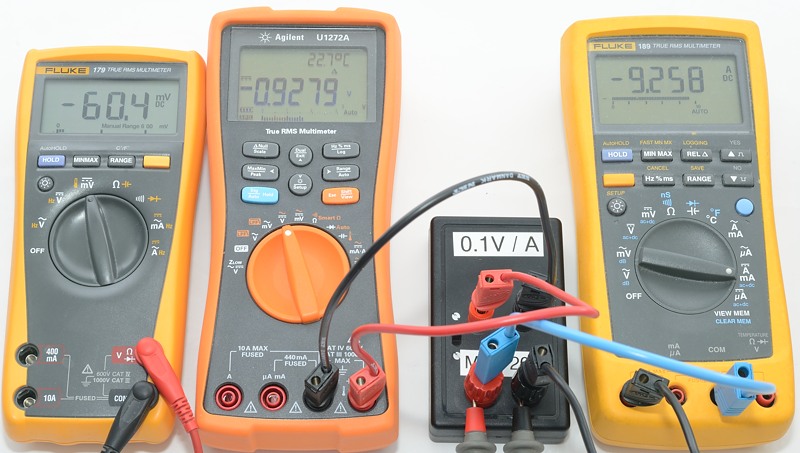
Test with about -9A.
Fluke 189: -9.258A
Agilent U1272A: -0.9279V -> -9.279A, difference from above is about 0.2%
Fluke 179: -60.4 mV in voltage drop, i.e. 6.5 mOhm resistance
This looks like a very good result.
Testing with flashlight
In this test I test current consumption on some single LiIon flashlights. I have not optimized the test leads for lowest possible resistance, but just used some standard high current test leads.
The DMM and the adapter will not show the same current, because the voltage to the light will depend on the resistance in the measuring circuit and the DMM has considerable higher resistance than the adapter.
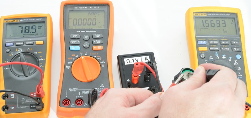
The first light is Klarus XT10 without the tailcap.
It uses 1.5633A according to my Fluke 189 and I has 0.0785 volt drop in the test leads.
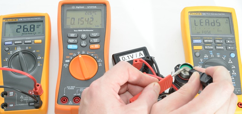
With the adapter I get 1.542A and a voltage drop of 0.0268 volt.
The difference between the two values is not really significant.
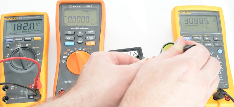
Next light is a 4Sevens S12, this light uses a 26650 battery and a SST90 led, I expect to see some serious current drain with this light.
With the Fluke 189 I get 3.0886A ampere and 0.182 volt drop.
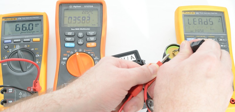
With the adapter I get 3.583A and a voltage drop of 0.066 volt.
This is a 14% difference, here the adapter does improve the result.
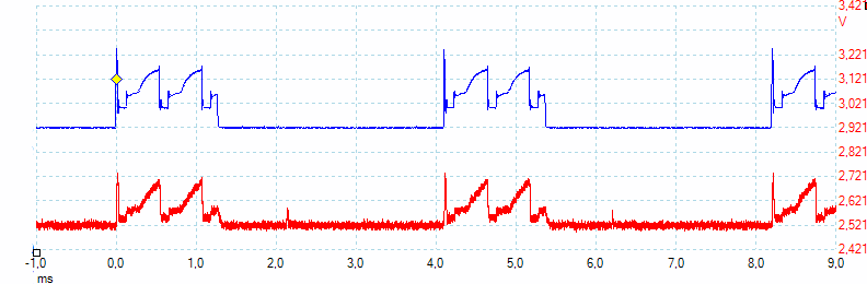
A test with an oscilloscope on the current adapter. For this test I uses a old Dereelight CL1H V3 with a P60 module. The blue trace is the light sensor and the red trace is the current adapter. With 0.1 V/A it means that the light is using about 2A in the peaks.
Conclusion
What do I get from this adapter:
Very low voltage drop.
Good accuracy up to 20A.
Is it worth the effort to build this adapter?
For most people probably not, the 10A range on a DMM is mostly good enough at 1A to 2A.
But people that works with higher current at low voltages, might need it.
It is also very useful for datalogging, either with a DMM or with a microprocessor based data logger where the galvanic isolation can be necessary.