Multimeter and pulsed DC current (PWM)
A multimeter usual can measure DC and AC but what happens when measuring a pulsing voltage or current?
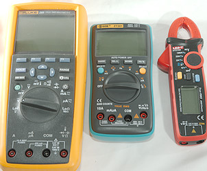
For this article I will be using 3. meters:
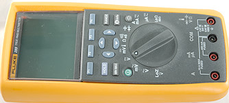
Fluke 289: A very expensive meter with just about everything.
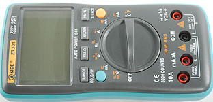
BSide ZT301: A cheap meter with all the common function.
UNI-T UT210E: A cheap clamp meter, I will only use this when looking at current.
This article is about pulsing DC, not AC
Contents
DC voltage
DC voltage BSide ZT301
DC voltage Fluke 289
What voltage do I use (DC / RMS / DC+AC)?
DC current
DC current BSide ZT301
DC current Fluke 289
DC current UNI-T UT210E
What current do I use (DC / RMS / DC+AC)?
Can a DMM Measuring maximum and minimum voltage/current in PWM
Power
Conclusion
Notes
DC voltage
In DC a multimeter will not use RMS circuit, but a averaging circuit.
I will use 3 waveforms for this:
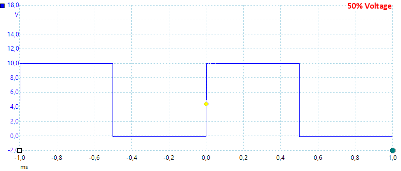
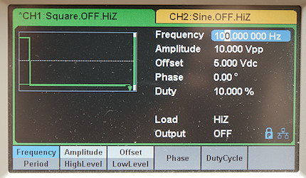
A 50% duty cycle waveform from 0V to 10V, this means the average voltage is 5.00V, a RMS meter will show 5.00V (It removes the DC component) and the DC+AC voltage is 7.07V, because it is a square it will contain much higher frequencies than the nominal frequency.
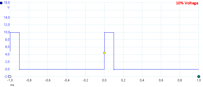
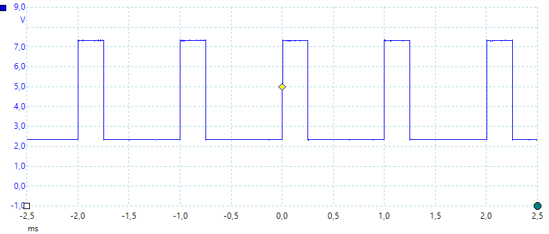
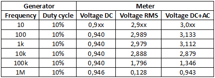
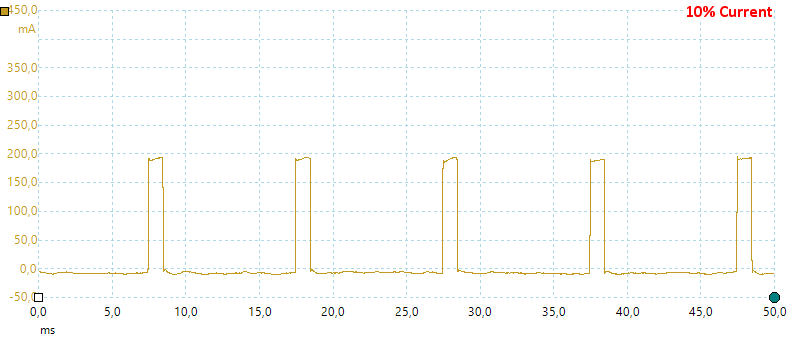
A 10% duty cycle waveform from 0V to 10V, this means the average voltage is 1.00V, a RMS meter will show 3.00V and DC+AC is voltage 3.16V, because it is a square with a 10% duty cycle the frequencies in this curve will be much higher than above.
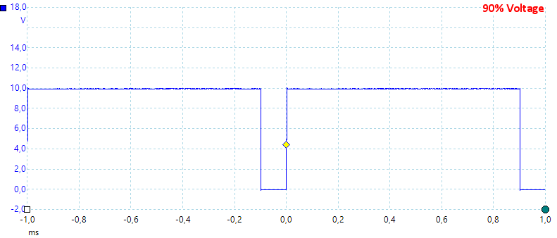
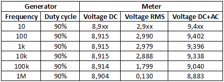
A 90% duty cycle waveform from 0V to 10V, this means the average voltage is 9.00V, a RMS meter will show 3.00V and the DC+AC voltage is 9.49, this will have the same high frequency content as the 10% curve.
DC voltage BSide ZT301
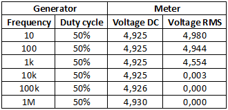
The meter shows average voltage correctly from 10Hz and up to 1MHz, but RMS is already wrong at 1kHz, because the meter do not have bandwidth enough to handle a 1kHz square wave.
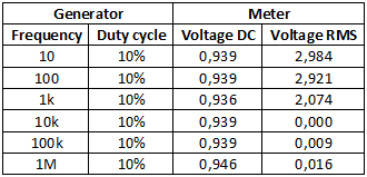
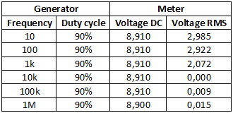
At 10% and 90% the DC voltage is shown correctly and the RMS is more wrong due to the more higher frequencies in the PWM signal.
DC voltage Fluke 289
This high end meter has much higher bandwidth, but it is not very good a 10Hz (It is too fast).
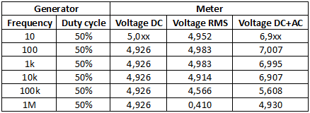
The average voltage is again correctly shown and the RMS works at higher frequencies. The DC+AC only works as far up in frequencies as the RMS works, because it is partially based on it.
With different duty cycle the DC is again correct, but the RMS and DC+AC will show wrong results at a lower frequencies.
What voltage do I use (DC / RMS / DC+AC)?
The interesting question is now what value to use? The answer is that it depends on application.
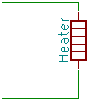
For a resistive heater it is the DC+AC value that is interesting.
An example:
1ohm heater with 10V: power -> sqr(voltage)/resistance -> 10*10 / 1 -> 100 Watt
When using a 50% PWM the power will 50% of that or 50 Watt, this could be calculates as sqr(DC+AC)/1 -> 7*7/1 -> 50 Watt
For 10% the power will 10% of that or 10 Watt, this could be calculates as sqr(DC+AC)/1 -> 3.16*3.16/1 -> 10 Watt
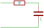
If the PWM goes to a filter to be converted to a DC voltage, then it is the DC that is interesting and the voltage will be proportional to the duty cycle.
DC current
For current I only use the 50% and 10% waveforms, but adds a meter more.
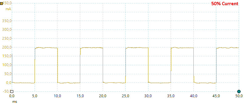
For the clamp meter I shorted the output of my generator, because it has a 50ohm output impedance and delivers 10V the current is 200mA. For the multimeters I added a 1kOhm series resistance, i.e. total resistance was 1050ohm, in addition to between 1 and 2 ohm in the multimeter
This average the current is 4.75mA for multimeters
This average the current is 0.95mA for multimeters
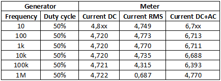
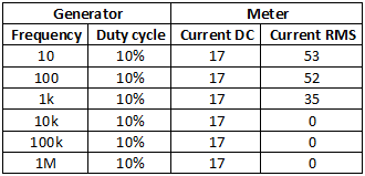
DC current BSide ZT301
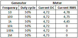
The DC works at all frequencies and the RMS is limited by the RMS converter in the meter, i.e. it cannot handle 1kHz correctly.
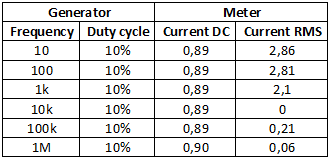
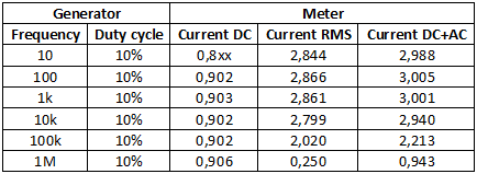
At 10% duty cycle the DC again works and the RMS drops a bit faster, at higher frequencies some of the signal is running around the converter inside the meter.
DC current Fluke 289
The DC works perfectly and the RMS can handle higher frequencies on this meter, the AC+DC reading requires RMS to be correct, before it can be correct.
No surprise here, the DC again works and the RMS drops of at higher frequencies.
DC current UNI-T UT210E
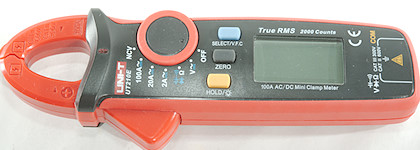
This is a clamp meter and I had to use higher current for it.
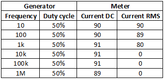
The behaviour is exactly the same as the other meters, DC works and RMS cannot handle higher frequencies.
Again the same.
What current do I use (DC / RMS / DC+AC)?
When working with DC the answer here will usual be the DC value, this is the current that will be drained from a battery or capacitor and also the current devices will use.
The exception is if you want to calculate power for resistors.
Another way to look at it:
DC measures the average current going to or from a device.
AC+DC (RMS) measures the total current going back and forth in a cable and weights it according to how much heat it generates.
With a clean DC the two values will be exactly the same.
With a pulsing DC they will be equal with a resistive load, but with anything else they will be different.
Can a DMM Measuring maximum and minimum voltage/current in PWM
This is mostly a job for an oscilloscope, multimeters are not fast enough.
If you can control the PWM it is easiest to measure DC voltage at highest and lowest PWM setting.
The min/max function on multimeteres usual requires about 0.3s or 300ms to measure a value, this means it cannot be used even at 10Hz.
Some meters has a "peak" function, this may be able to measure 1ms or even 0.1ms peaks.
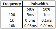
From the above table it is fairly obvious that even the peak function is too slow when the PWM frequency gets much above 100Hz.
Power
When working with pulsed current or PWM you cannot just multiply voltage and current to get power, here the RMS (or rather DC+AC) values can be useful.
Example:
0V to 10V with 10% duty cycle will delivering 0A at 0V and 1A 10V.
It is easy to calculate that it will deliver 10 watt when (Voltage x Current -> 10 x 1) on and with 10% duty cycle the power is 1 Watt.
But using the DC values that is 1V (10% of 10V) and 0.1A (10% of 1) gives 0.1 Watt, i.e. very wrong.
What about DC+AC values, that is 3.16V and 0.316A and gives the correct 1 Watt.
But there is a caveat on that, the RMS part will include current running both ways, this is fine for dimensioning the cable and calculating power for resistors, but when the circuit has a inductor or capacitor that returns some current each cycle, the above power calculations will fail!
Conclusion
When measuring on PWM it is important to know what the result must be used for, average is useful for some measurement and AC+DC is required for other (If meter is missing AC+DC use a calculator, see below).
The bandwidth on multimeters is for AC measurements including DC+AC, but DC measurement usual works at much higher frequencies.
Notes
For meters without DC+AC it can be calculated this way: DC+AC = sqrt(sqr(DC)+sqr(AC))
In this article I assumes DC+AC is based on the true RMS value of the AC (I have not seen AC+DC on a non-true-RMS meter)