Multimeter and voltage measurements
In this article I will look at voltage measurement with a voltmeter and the pitfalls. I will use fairly simple setups, mostly with test equipment, the situations shown will exist in a lot of places where it might be relevant to measure voltage.
Contents:
Simple DC measurement
DC measurement and impedance
Mains measurement
Zeroing offsets on meters?
AC+DC measurement
Measuring ripple, small AC voltage on large DC voltage
AC frequency
True RMS, crest factor and waveform
Peak AC pitfall
RMS on DC ranges
High voltage
Conclusion
Notes
Simple DC measurement
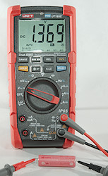
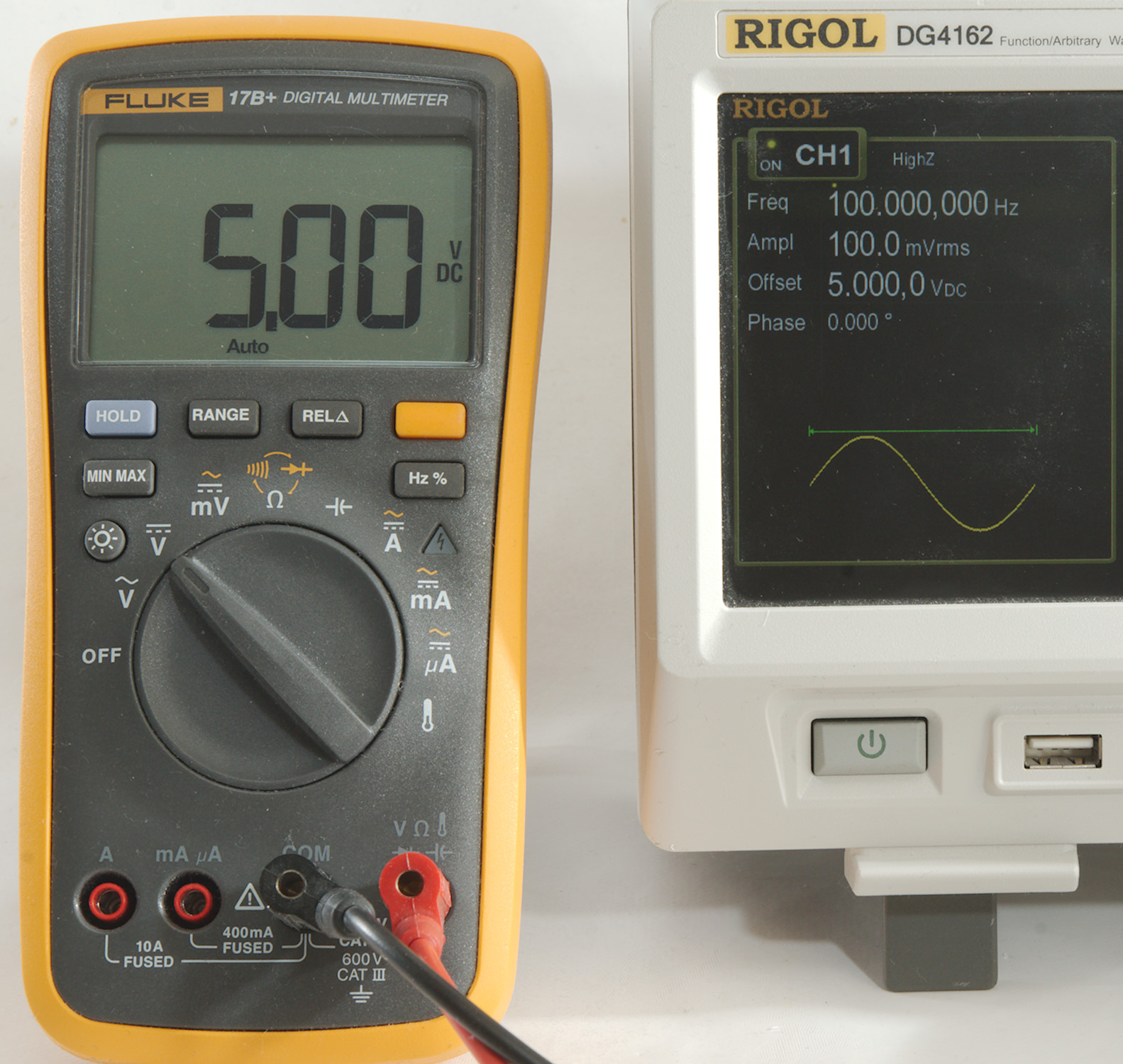
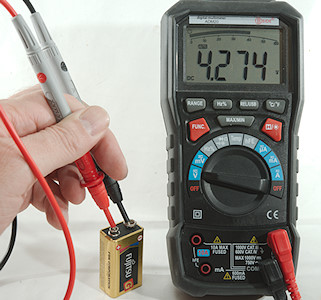
Select DC voltage, plug the probes in COM and VDC input and just touch the two points where you want the voltage between and the display will show a result with lots of digits. It will usual be exactly the voltage between the two points, as least while the multimeter probes touch them. Sometimes it is necessary with some pressure to punch through a layer of oxidation.
The + voltage is at the red probe and the negate is at the black probe as long as red and black is connected to the read and black terminals on the meter. If the voltage is the other way around the meter will some a minus before the voltage.
DC measurement and impedance
Most multimeters have 10Mohm in input impedance, when measuring on batteries or other power sources this is a high impedance and will usual not affect the result significantly, but measuring on sensors or in a circuit it may.

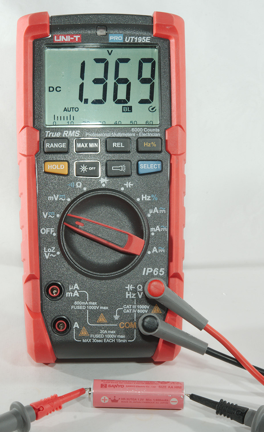
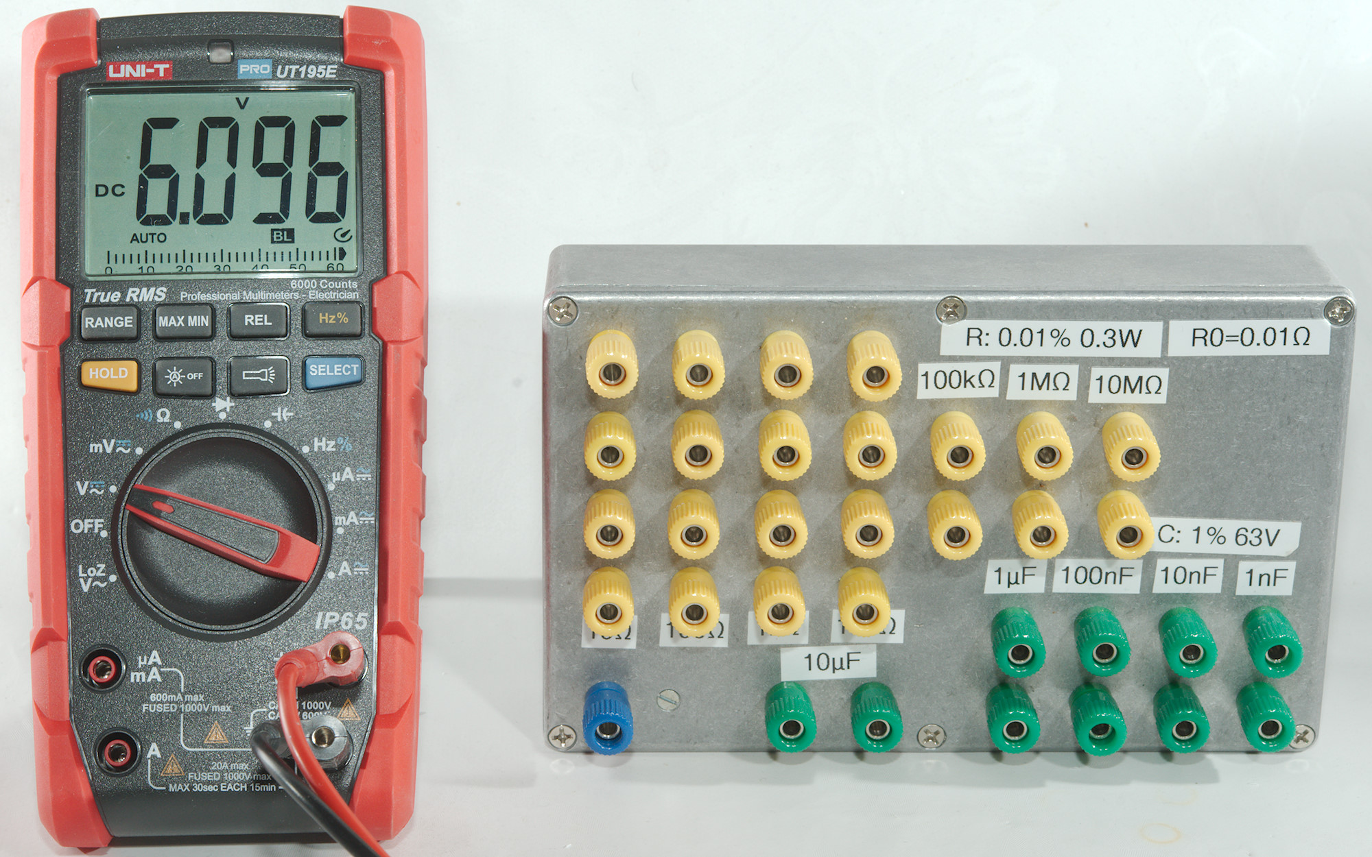
Here I am using a power supply as source and a standard good quality multimeter.
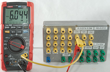
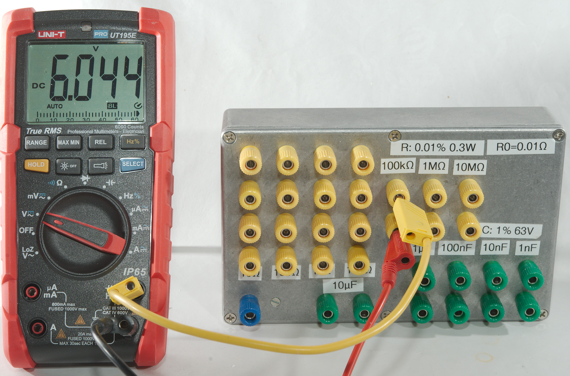
Adding a 100kOhm resistor in series with the power supply will affect the voltage slightly.
This meter has 11.1Mohm input impedance in this range and using calculations for a voltage divider I get: 11.1M/(100k+11.1M)*6.096 -> 6.042

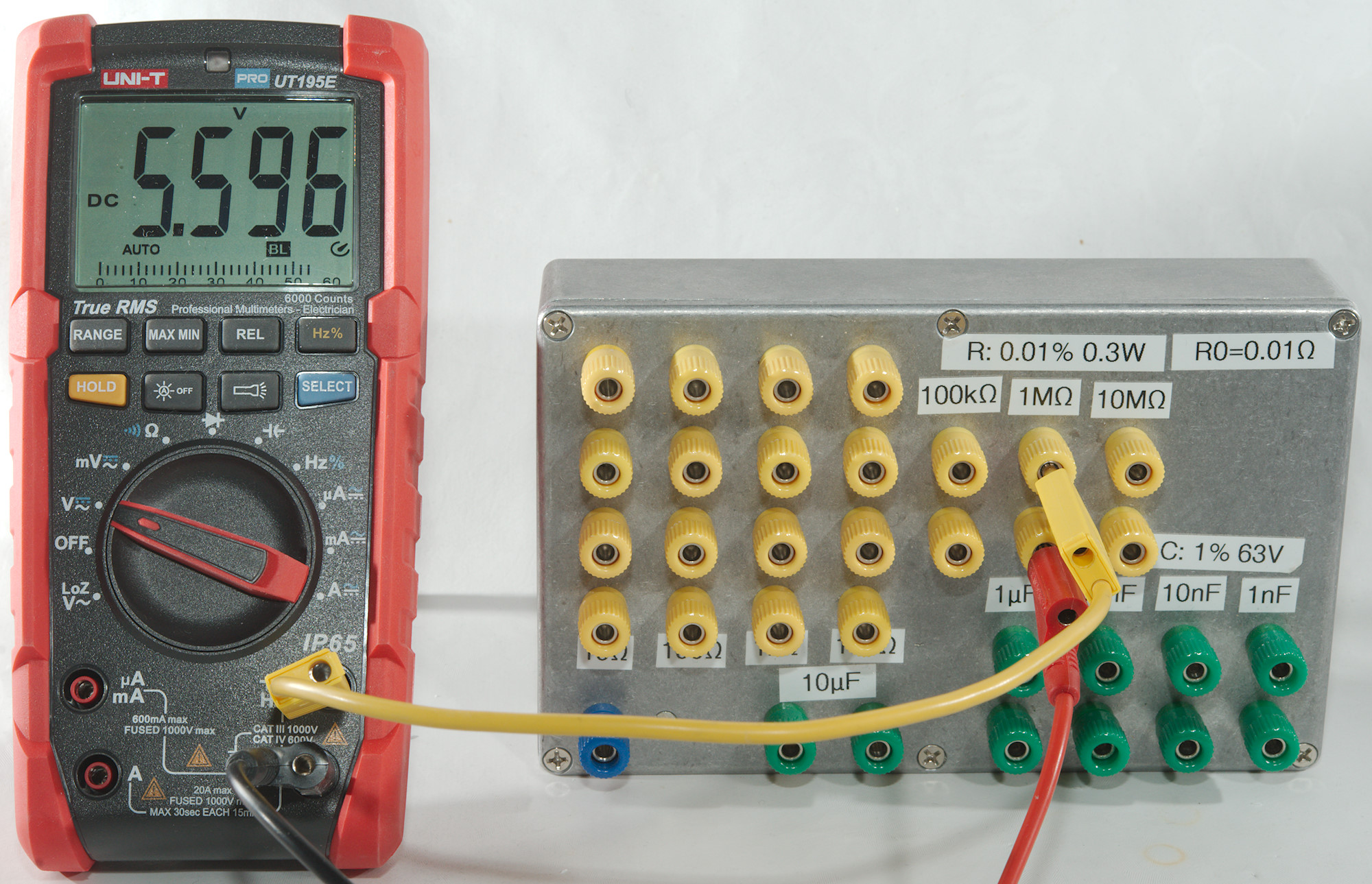
Increasing the resistance to 1Mohm will reduce the voltage more and it may be time to use the divider calculations the other way around:
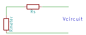
Vcircuit=MeterReading*(Rmeter+Rs)/Rmeter -> 5.596*(11.1M+1M)/11.1M -> 6.100 volt.
Using the standard 10Mohm value it would be: 5.596*(10M+1M)/10M -> 6.156 volt, not as precise, but better than without compensation.

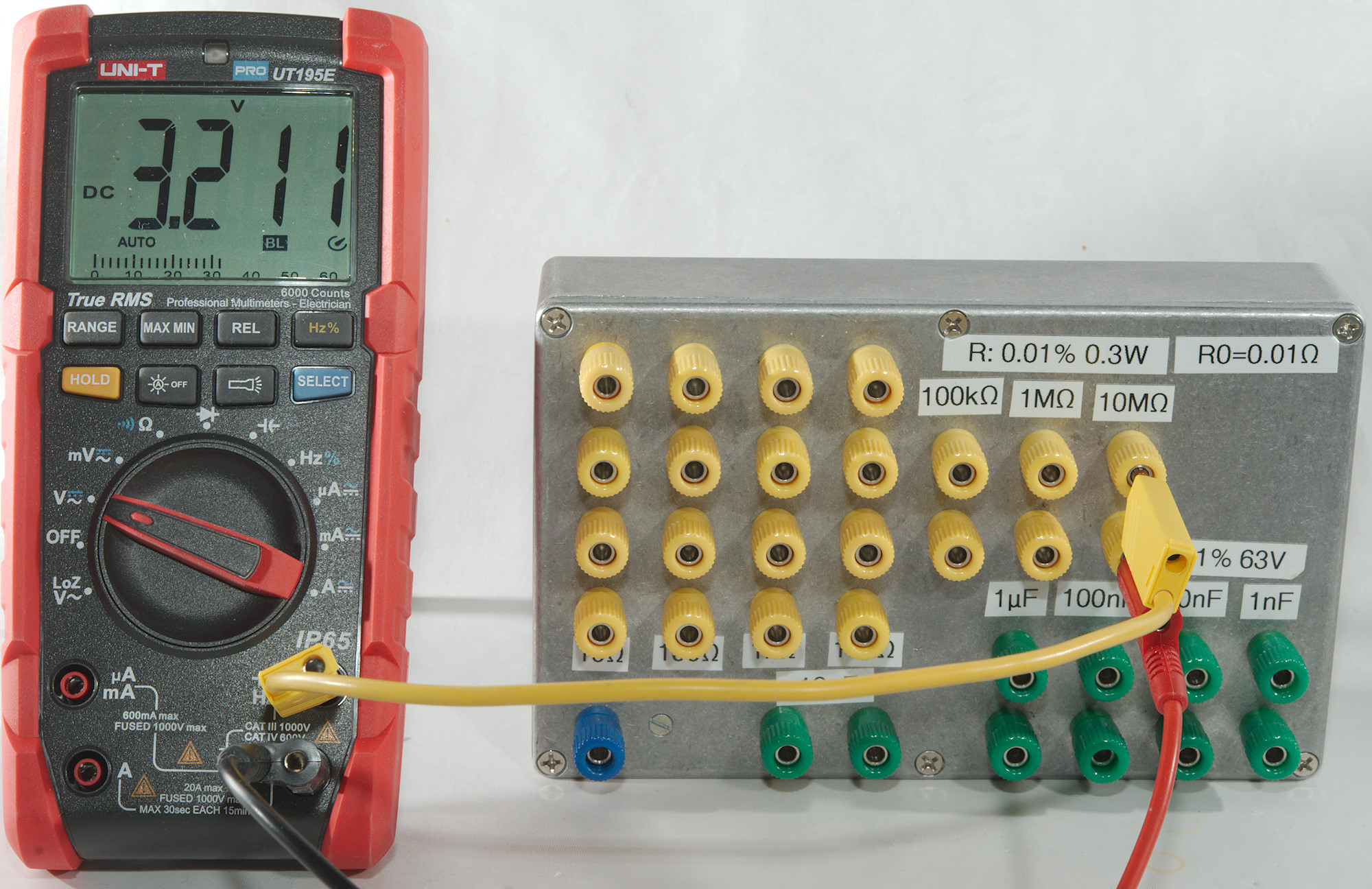
And if the impedance get even higher, the result are getting worse, but doing the calculations can help:
Vcircuit=MeterReading*(Rmeter+Rs)/Rmeter -> 3.211*(11.1M+1M)/11.1M -> 6.104 volt.
There is, of course, a practical problem, you will not always know the circuit impedance, this means it is not possible to do this calculation.
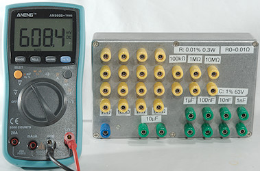
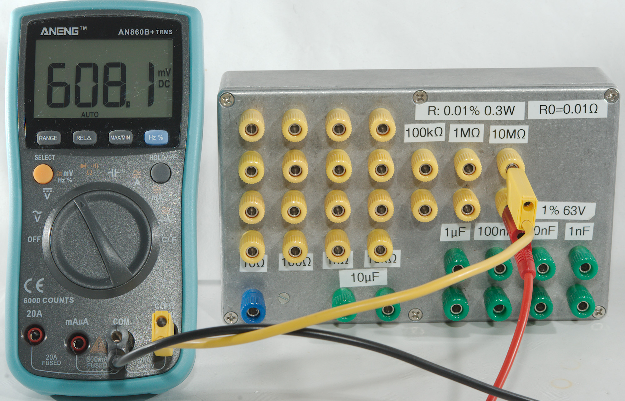
Many meters has a very high input resistance in the DC mV range, here I have turned the power supply down to 608mV.
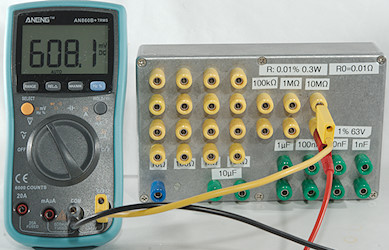
And the 10Mohm resistance do not really affect the result.
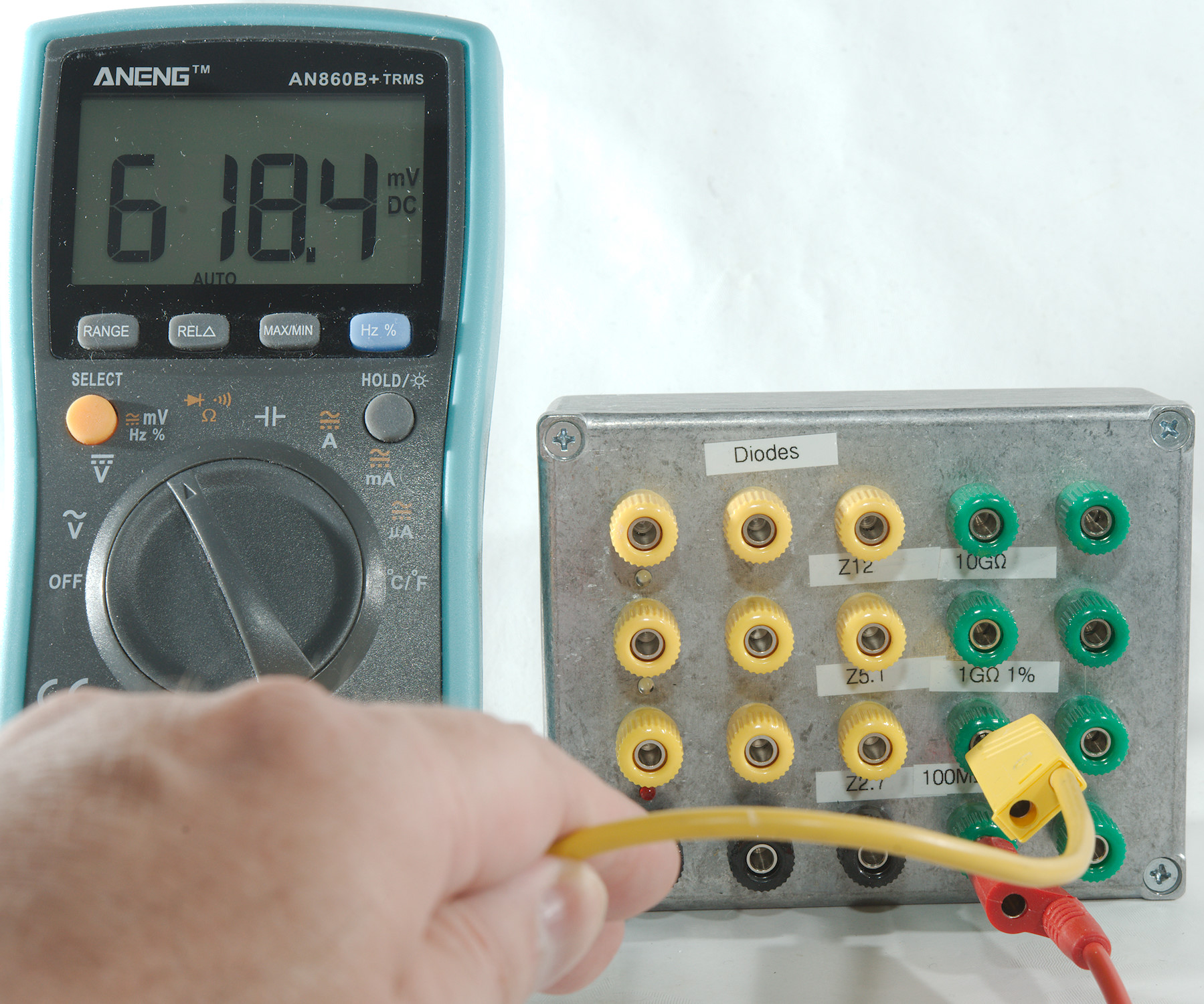
Even with 100Mohm I get a good result.

But not if I move close to the wires or touch them, using handheld probes is rather problematic when working with high impedance.
Many bench meters have high input impedance up to a bit above 10VDC, for measuring even higher voltage from a high impedance a elektrometer is required, it is rather expensive.
Mains measurement
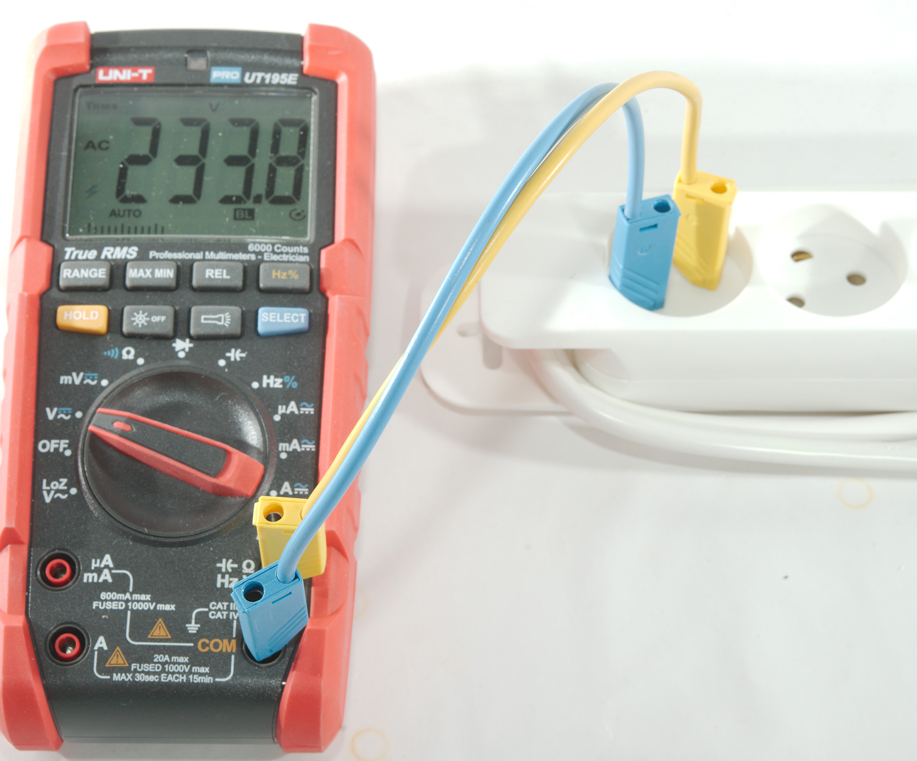
When measuring on mains voltage it is important to be careful, the voltage can be deadly.
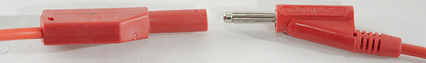
To reduce the risk it is a good idea to use shrouded plugs.
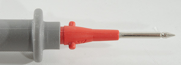
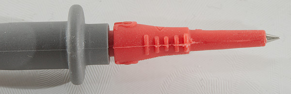
And covered probe tips. When working with industrial power the covered tips are required.
Nearly all meters has a CAT rating specifying a number from I to IV and a voltage, this is supposed to be the safety rating on the meter, but nearly all cheap meters are wrongly marked with a much higher rating than they are designed to handle. I explain a little bit about them here.
I do not use shrouded probes or covered tips here, mostly because I need a fixed setup and turn the power off when moving the wires around.
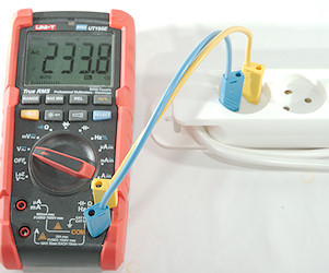
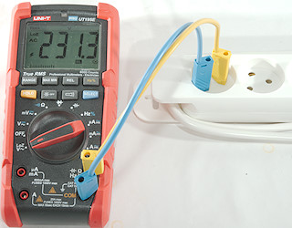
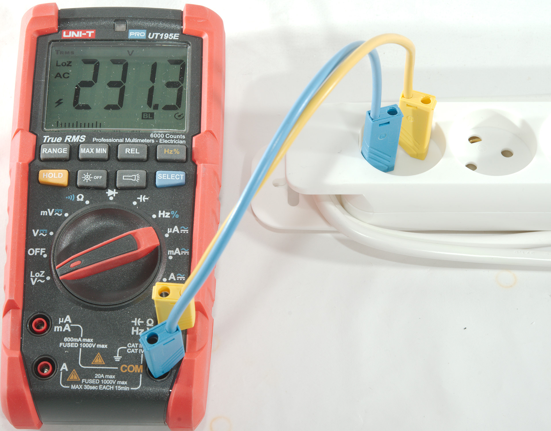
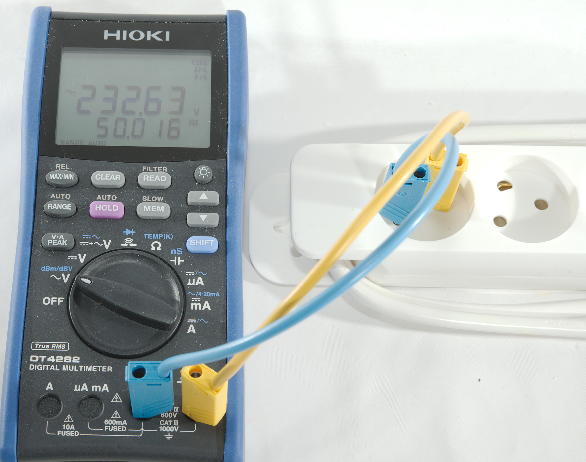
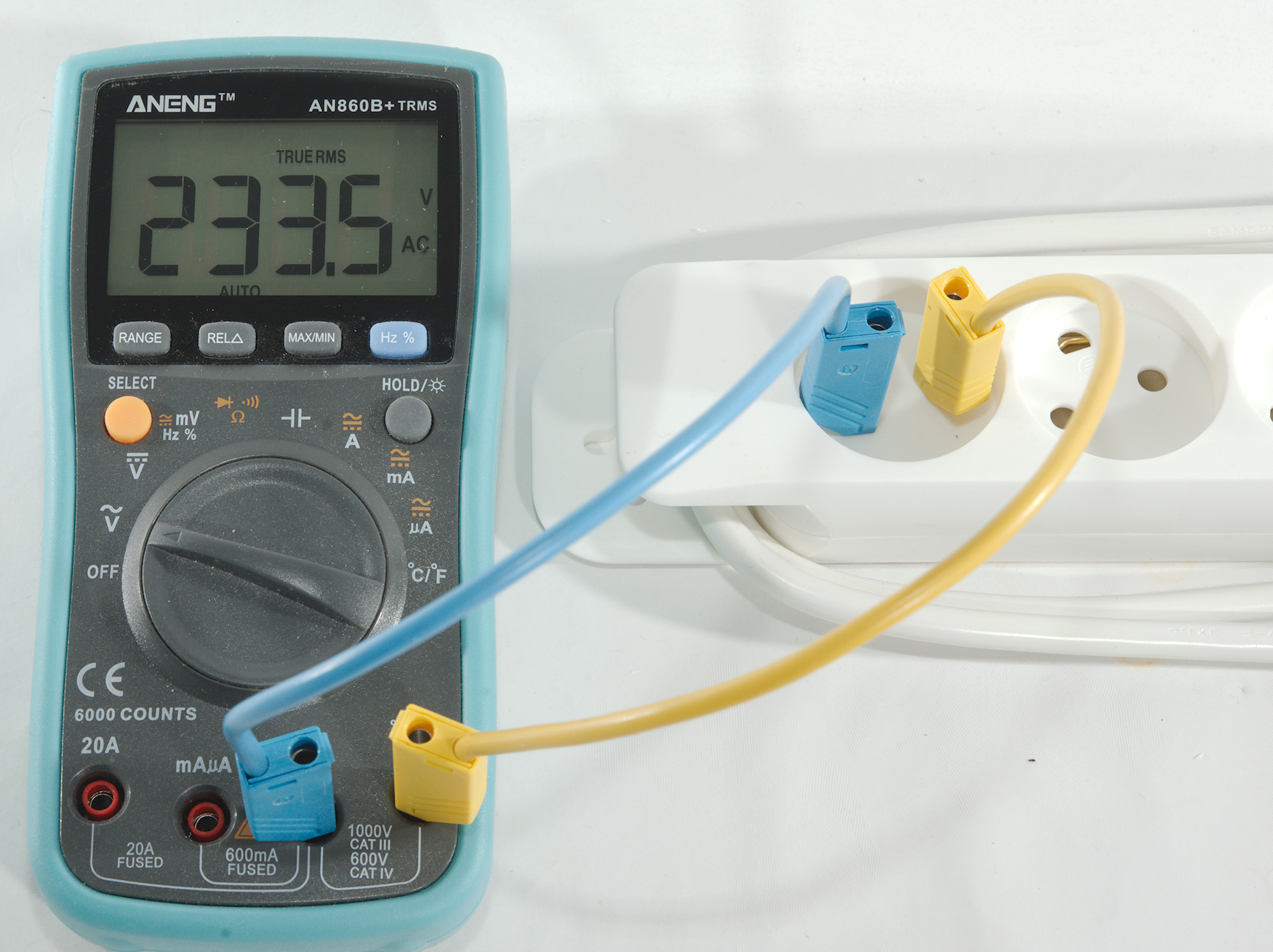
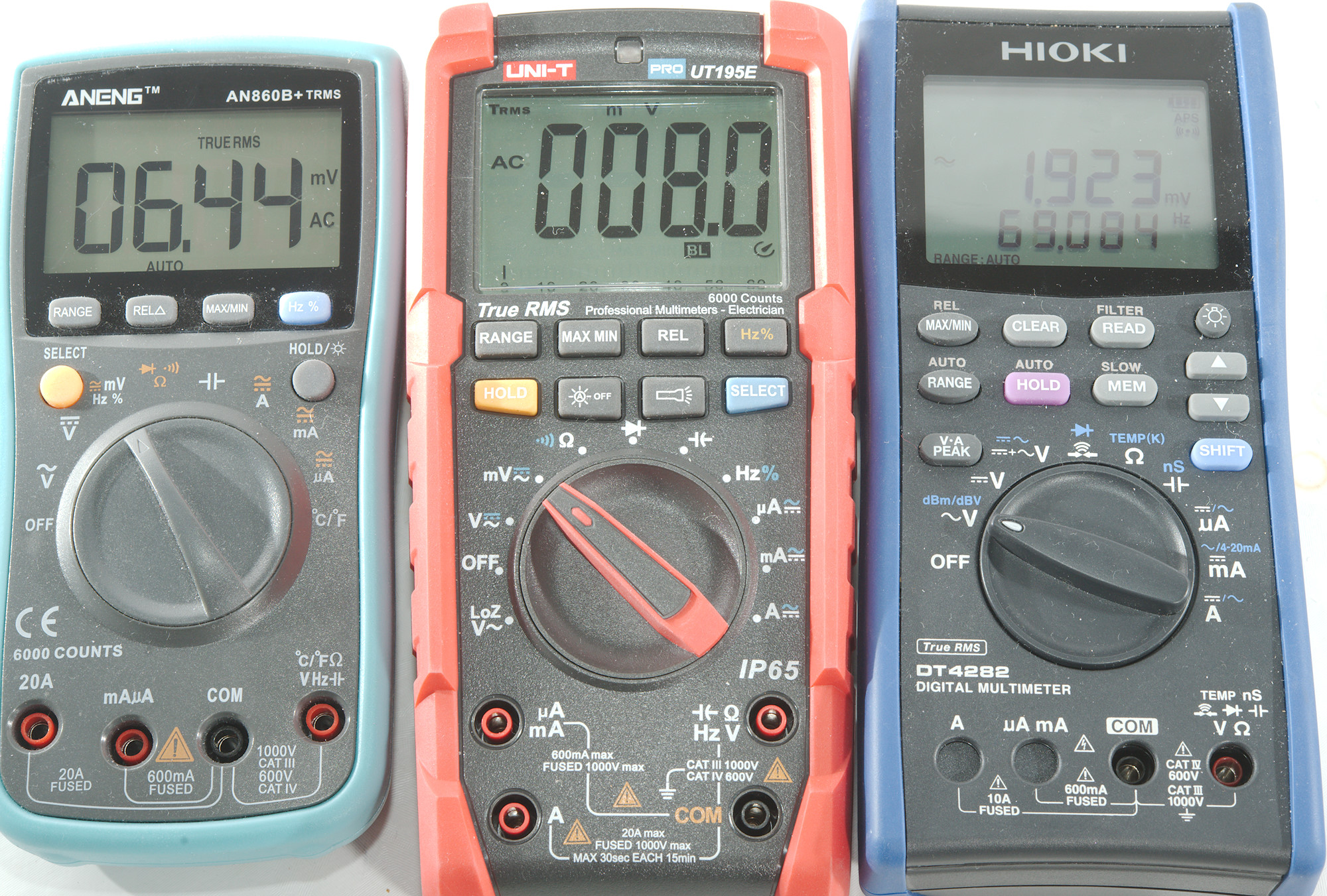
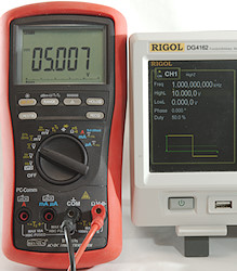
This meter has two AC settings, one called LoZ AC and a normal AC, they basically gives the same reading here.
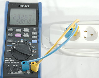
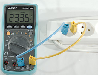
And two other meters also gives the same result.
Anytime somebody in the area turns something on or off the voltage will vary a bit, if I want to see if the meters gives the same result I must connect them all at the same time or use my electronic AC generator.
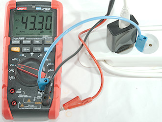
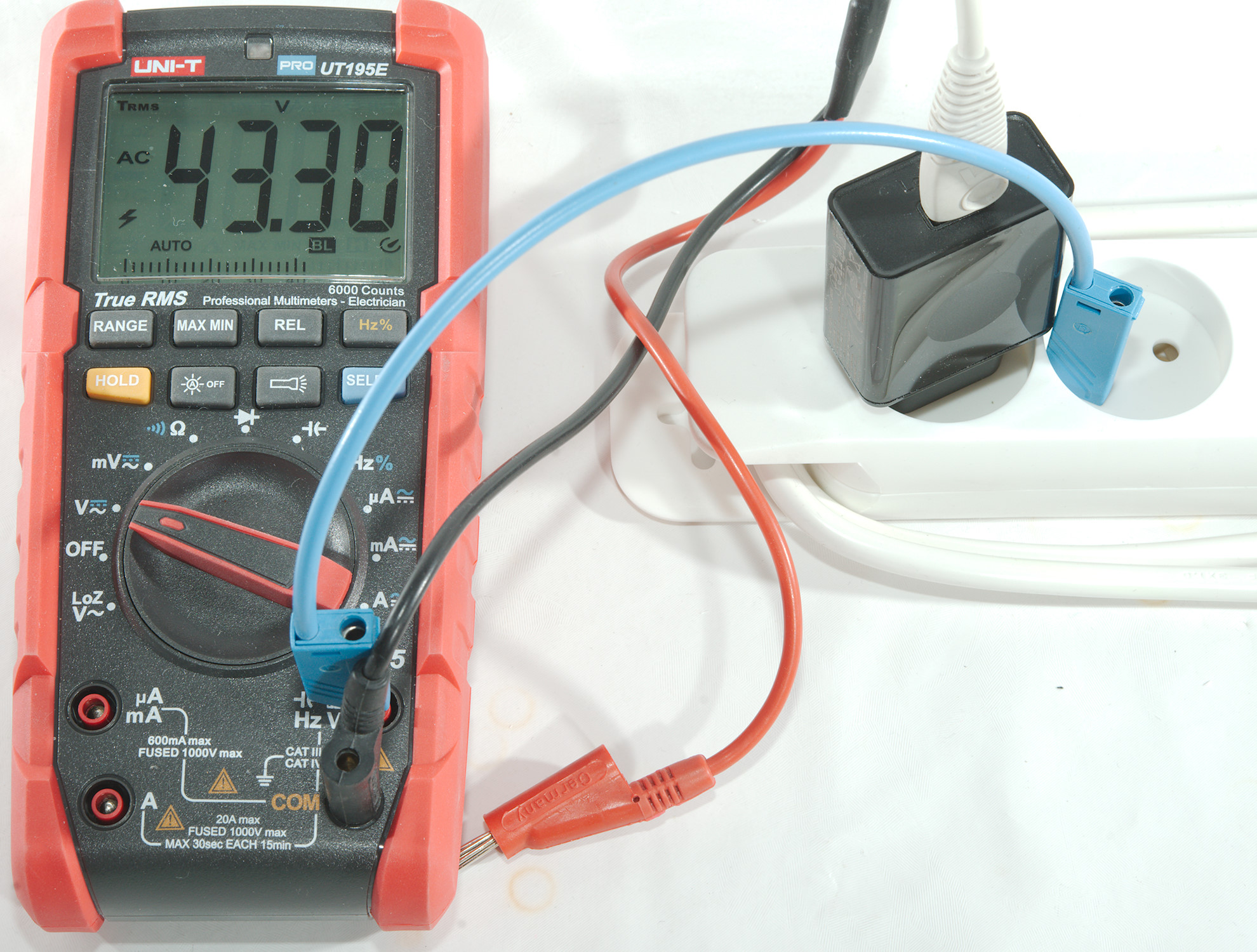
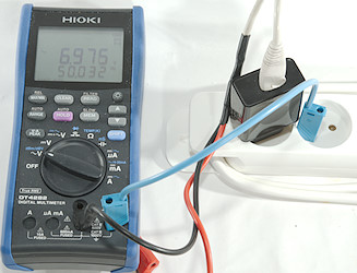
Lets try something else: What is the voltage between a low volt DC supply and the mains?
Mains voltage uses two wires, often called "Live" and "Neutral". Neutral is close to 0 volt compared to the earth and Live is 100VAC to 250VAC depending on where in the world you live. The output of a USB power supply is not supposed to have any connection to either Live or Neutral, especially because you can plug it in either way around.
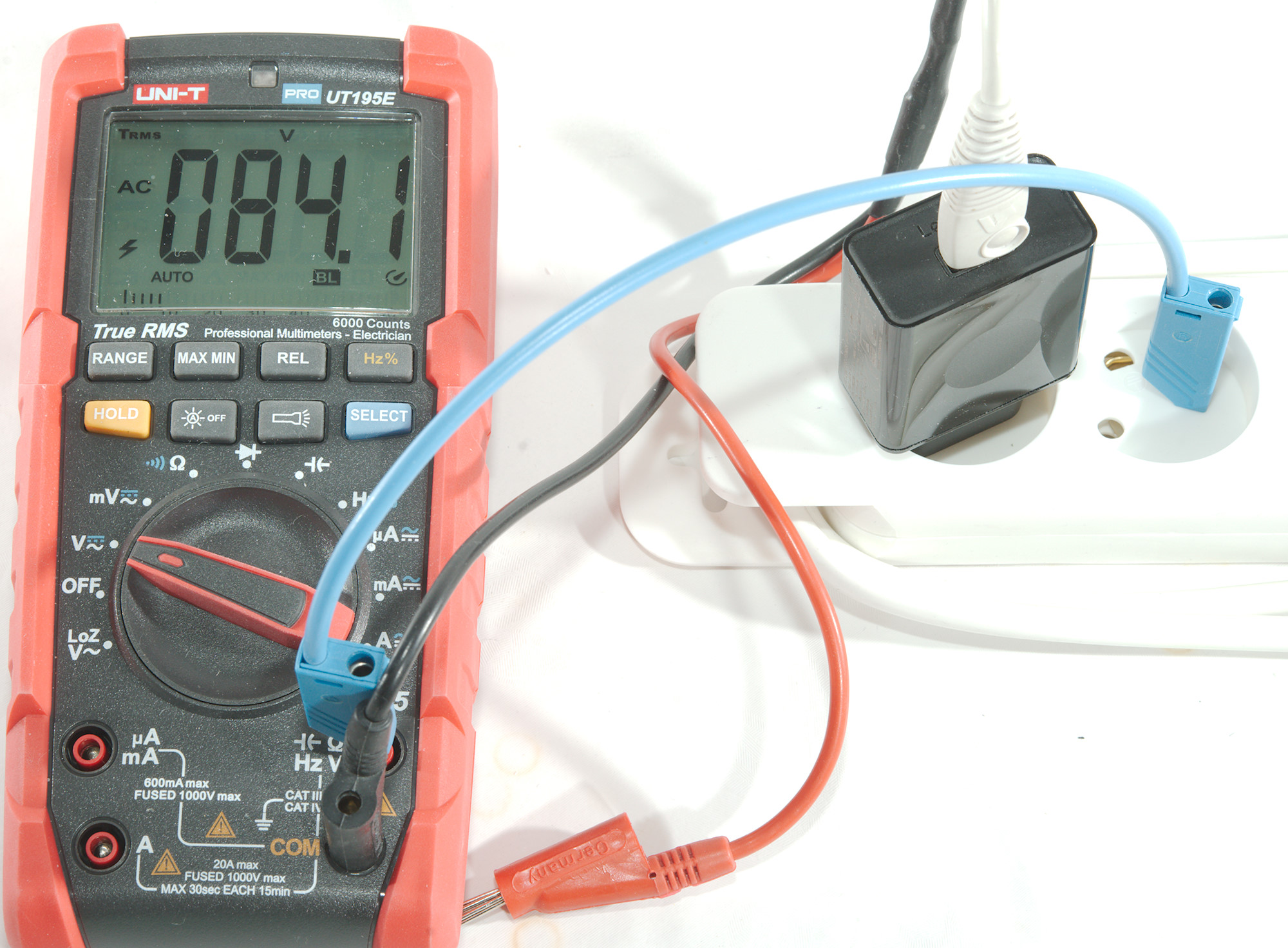
Here I do measure some voltage, both to Live and Neutral, is there something wrong with the usb power supply?
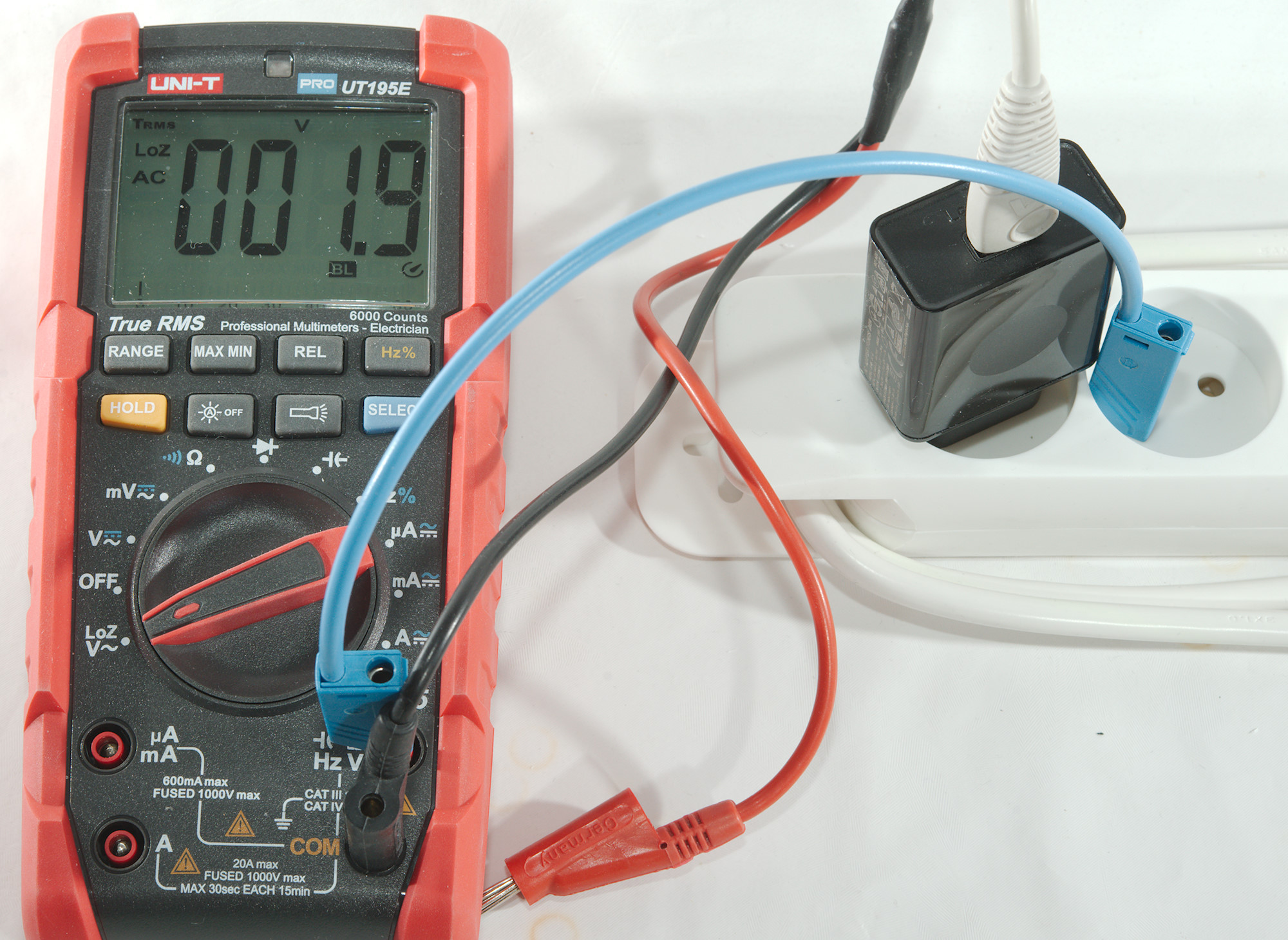
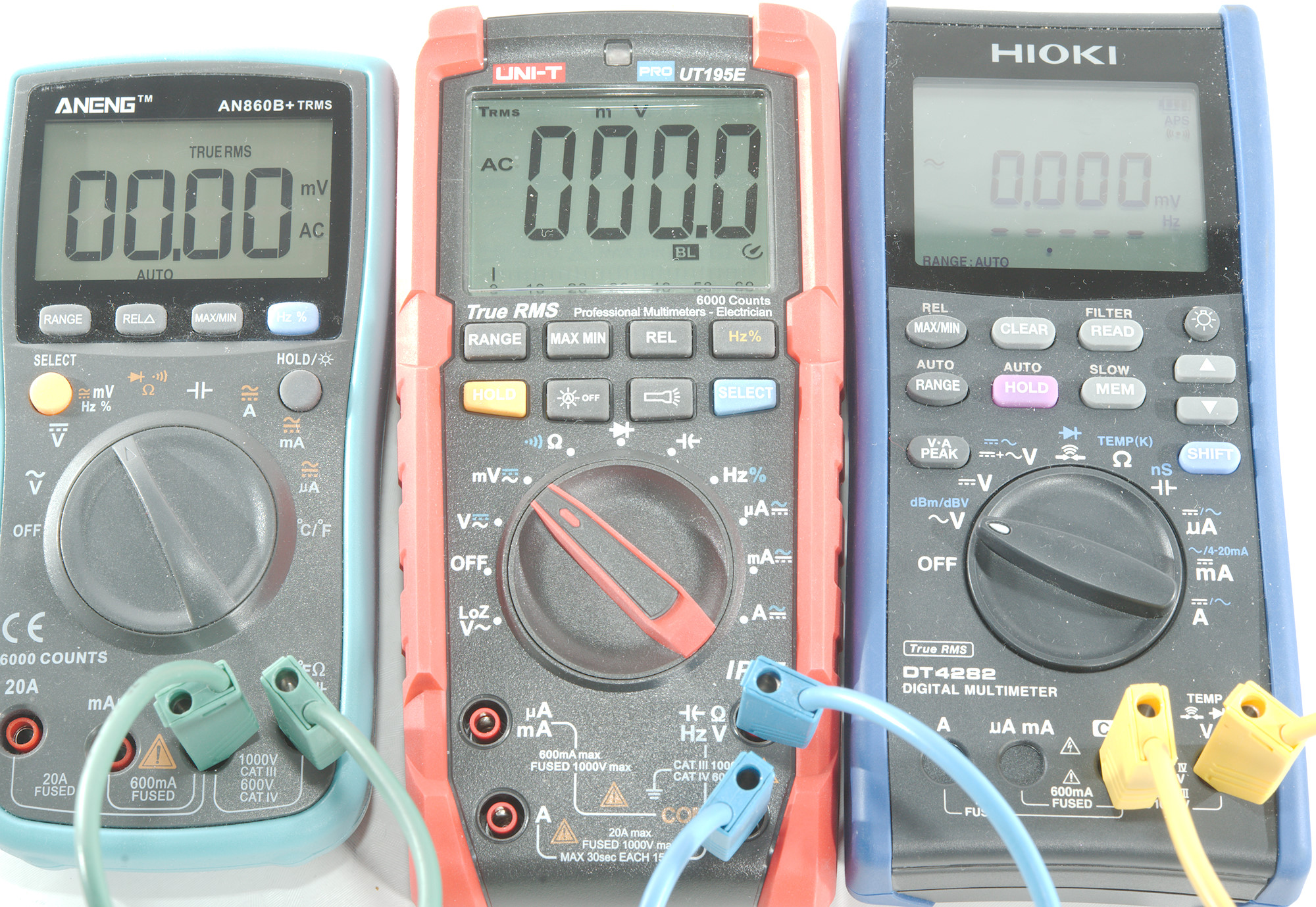
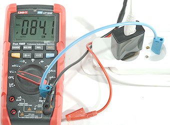
The answer is no, using the LowZ mode the voltage basically disappears. The reason for the voltage is a safety capacitor in the supply, this can be seen in all my usb power supply reviews and in my SMPS explanation.
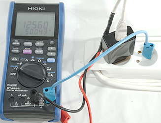
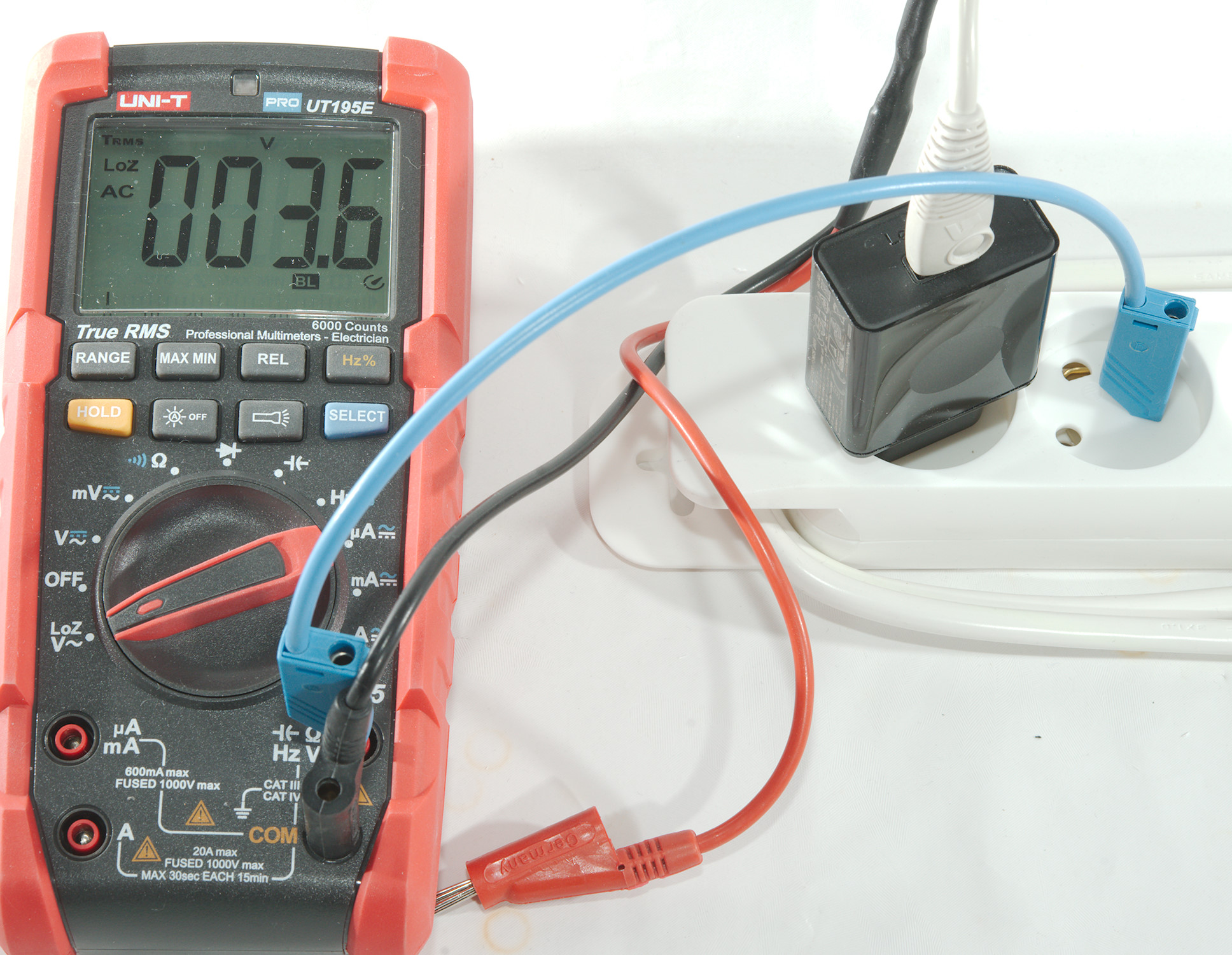
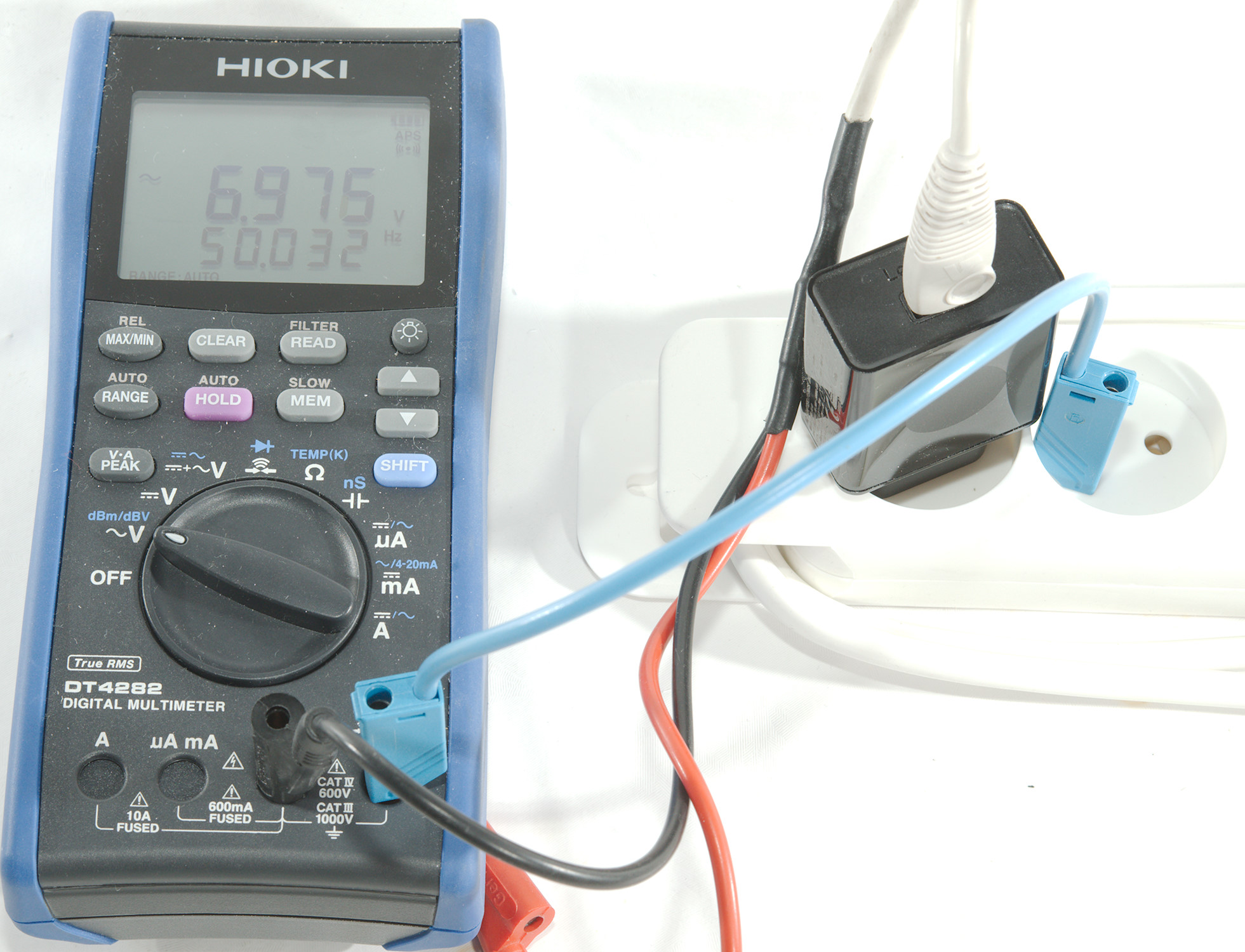
This meter is not marked as a LowZ meter, but it has a lower input impedance on AC and again the voltage drops significantly.
Most power supplies with a unconnected earth terminal will show a voltage midway between Live and Neutral, but using the LowZ function will show a very low voltage (This is due to a filter at the input).
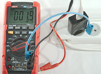
The LowZ function is implemented in two different way and it is important to know which way a meter uses. Some meters has a input impedance in the 300k to 1Mohm range, if this pulls down the voltage, it is basically a harmless voltage.
Other meters uses a PTC with only about 2-3kOhm impedance initially, this will pull down most voltage that cannot deliver power, but they may still be a bit nasty to touch and using this LowZ function between earth terminal and a live terminal will often trip a RCD/GFI breaker.
Where this function is really useful is when two wires are besides each other for some distance, due to capacitive coupling and/or leakage current both wires may show a high voltage on a meter with 10Mohm input impedance, but the LowZ function will reveal what wire do really have voltage.
Zeroing offsets on meters?
Using the DC mV range there is some offset on the meters, this offset is not something that needs zeroing out, but is due to electrostatic pickup from the environment and leakage inside the meter.
When shorting the input it will go away. The Hioki has a offset of 5uV now and this can be removed with the REL button.
There is also offset on the AC mV range, because there is always some "hum" in the air and a sensitive meter will get some of it, even without probes connected, again there is no reason to zero this.
Shorting the meter and it goes to zero, at least in this case. It may not always go to zero, sometimes it will still show a value. This is due to the AC to DC conversion, many converters do not work at the low voltage, specification will usual say that anything below 5% to 10% of full scale is invalid.
Do not use REL to remove small AC offset values, the meter is calibrated with this and will not be as precise if REL is used.
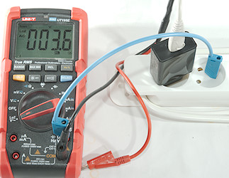
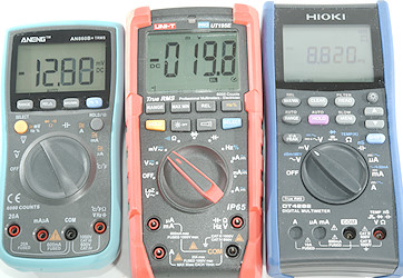
AC+DC measurement
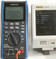
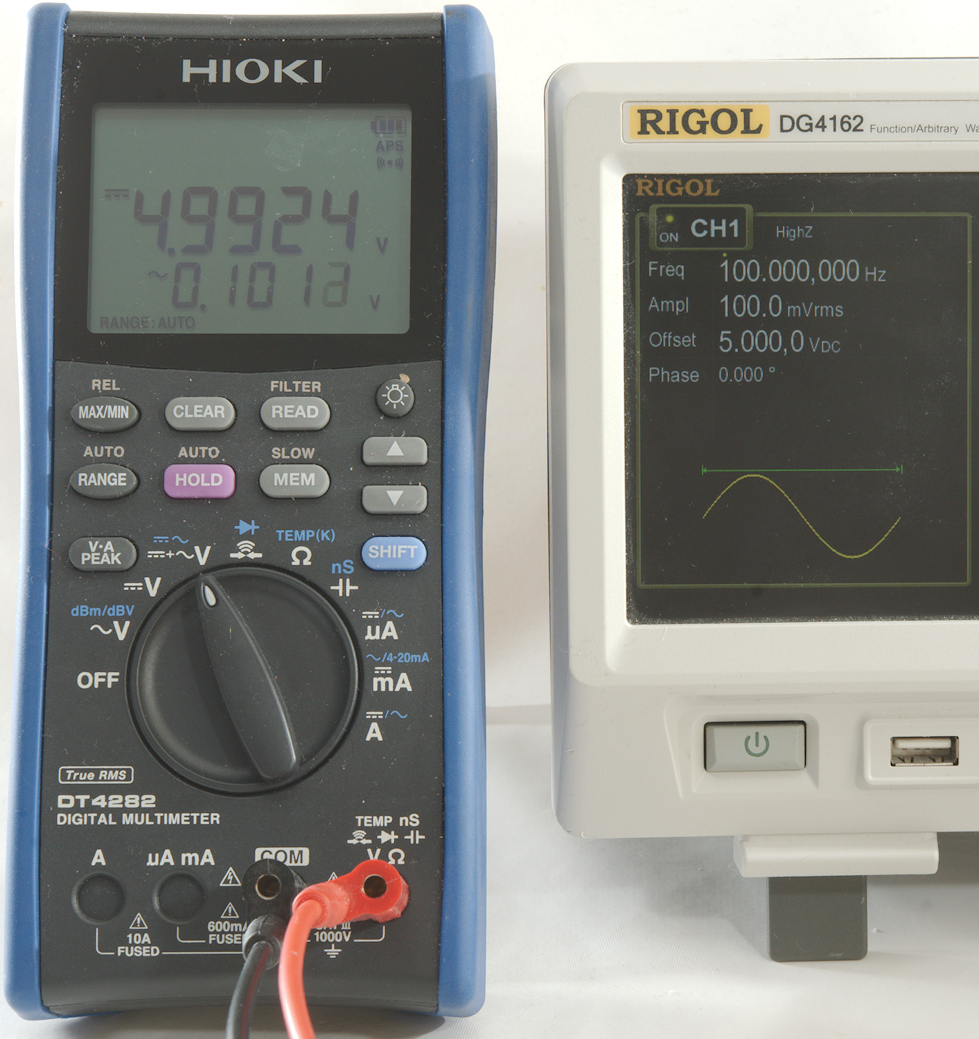
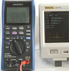
A voltage may contain both AC and DC components, most meters will split them and only show the AC part in AC settings and the DC part in DC settings.
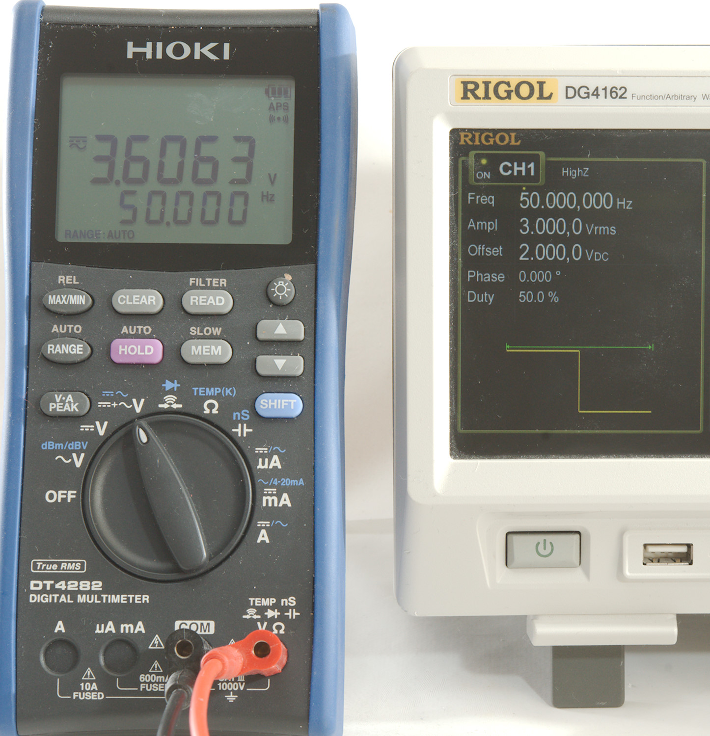
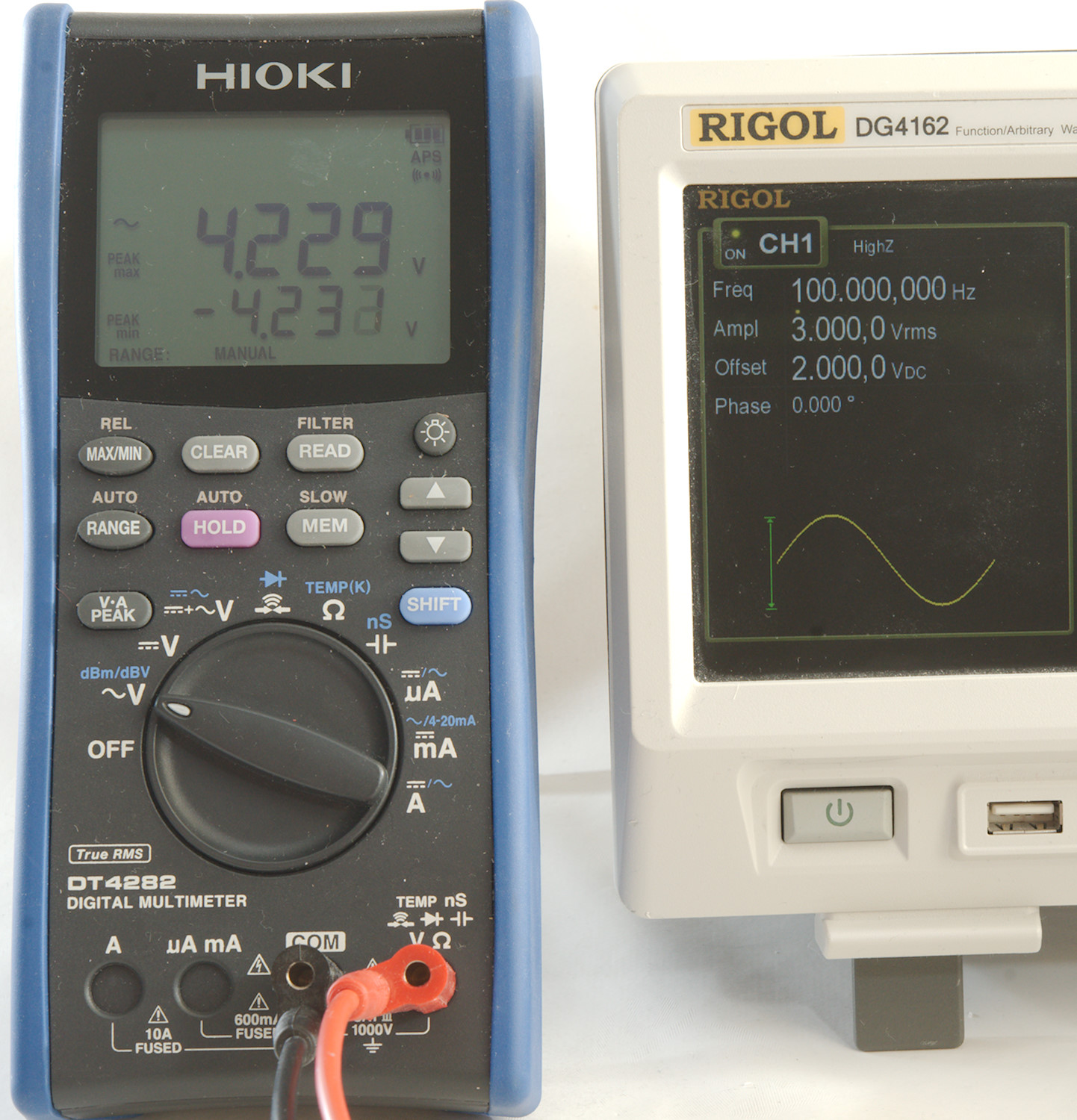
The AC part is what you would get after a capacitor and for this reason some multimeters have a capacitor in series with the AC input. The Hioki has two AC ranges, one with a capacitor and one without, here I am using the one without capacitor and it can show both AC and DC components at the same time. This is not called AC+DC but maybe AC,DC.
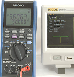
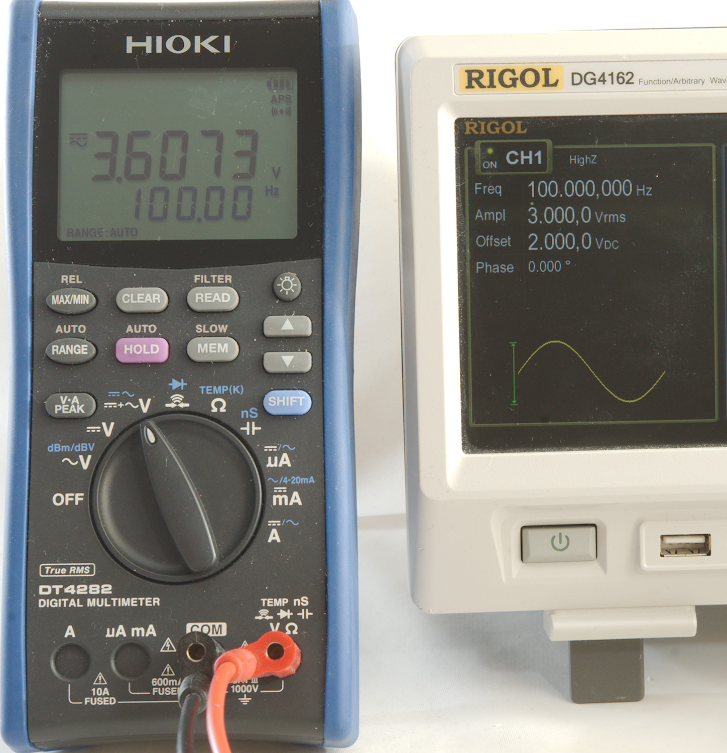
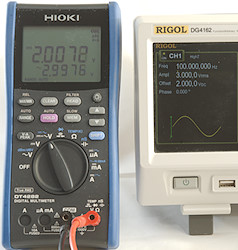
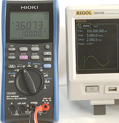
Selecting the AC+DC function will add the two voltages together, this is not direct addition, but requires some mathematic: AC+DC=sqrt(sqr(AC)+sqr(DC)) -> sqrt(sqr(3)+sqr(2)) -> sqrt(9+4) -> 3.6056
Measuring ripple, small AC voltage on large DC voltage

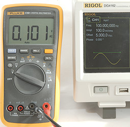
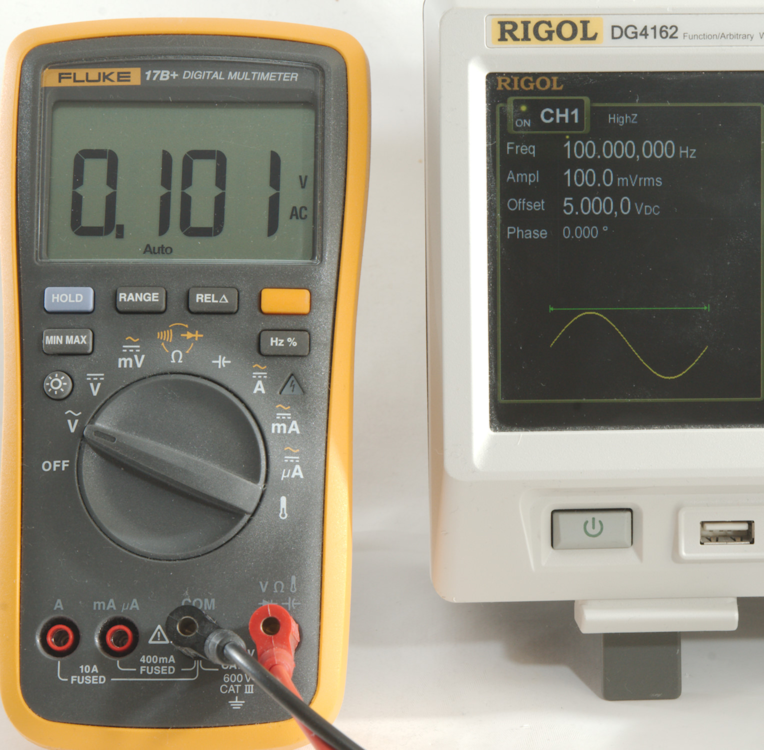
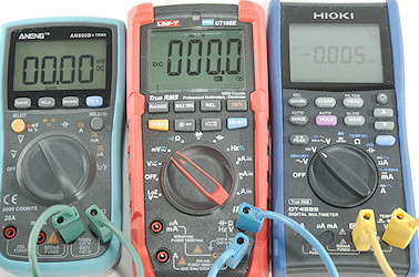
A DC voltage with a small AC ripple on it must be easy to measure, use the DC range to measure, switch to AC and measure the AC voltage.
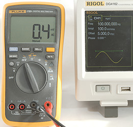
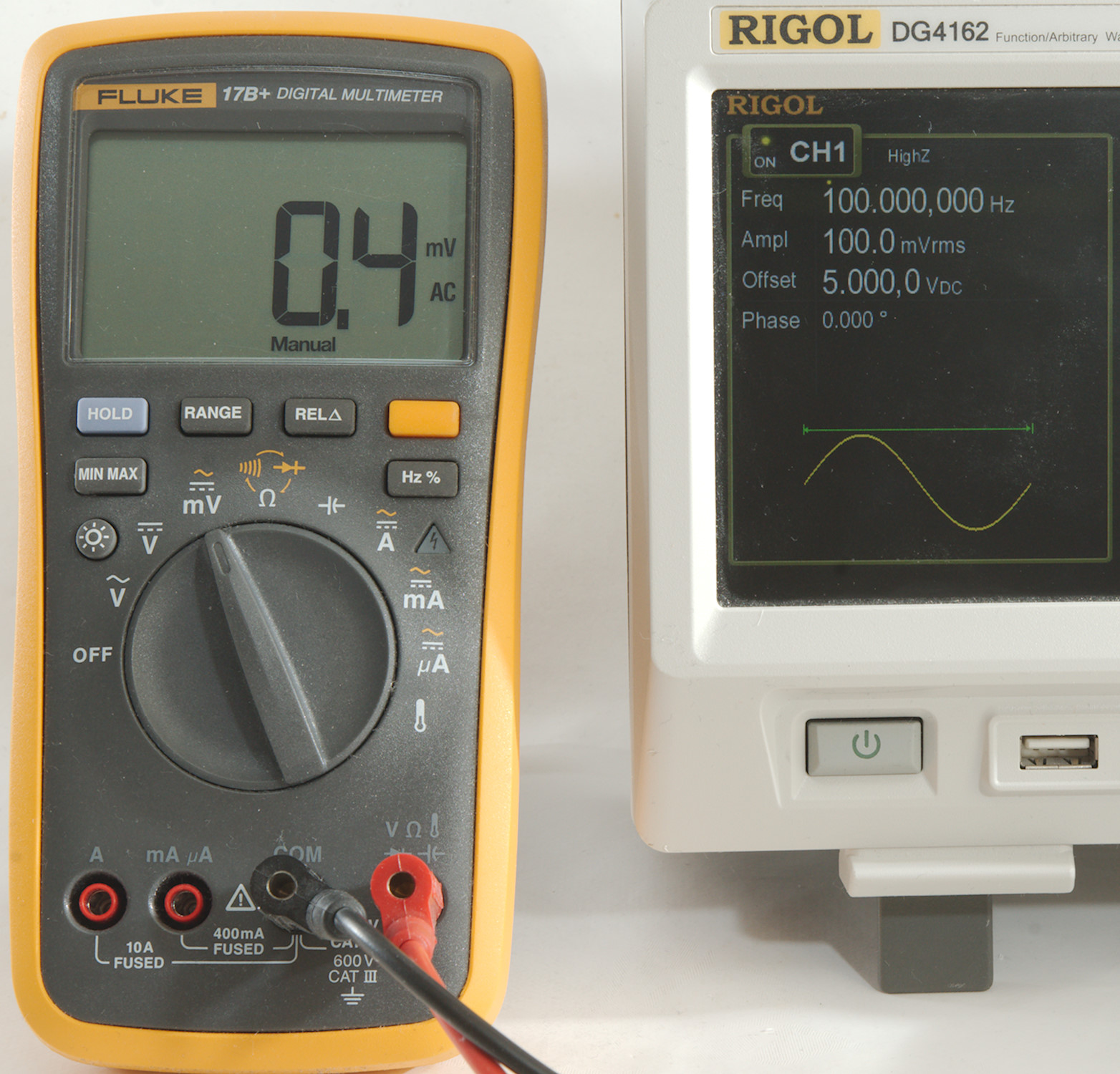
And if I want a bit better resolution use the AC mV range. Something is wrong, I got 100mV above, but only 0.4mV here?
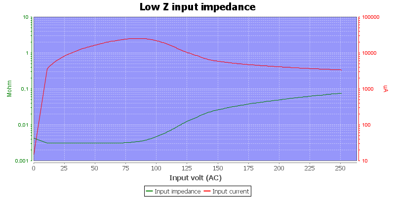
This is something most multimeters will fail at, only multimeters with a capacitor on the AC mV input will handle it correctly.
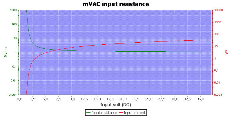
Here is the input DC impedance of the AC mV range, it is rather low at 3V, because the protection in the multimeter input has kicked in. Multimeters without a capacitor will clamp mV input for both DC and AC, the mV range will only show correct value when both are inside the mV range!

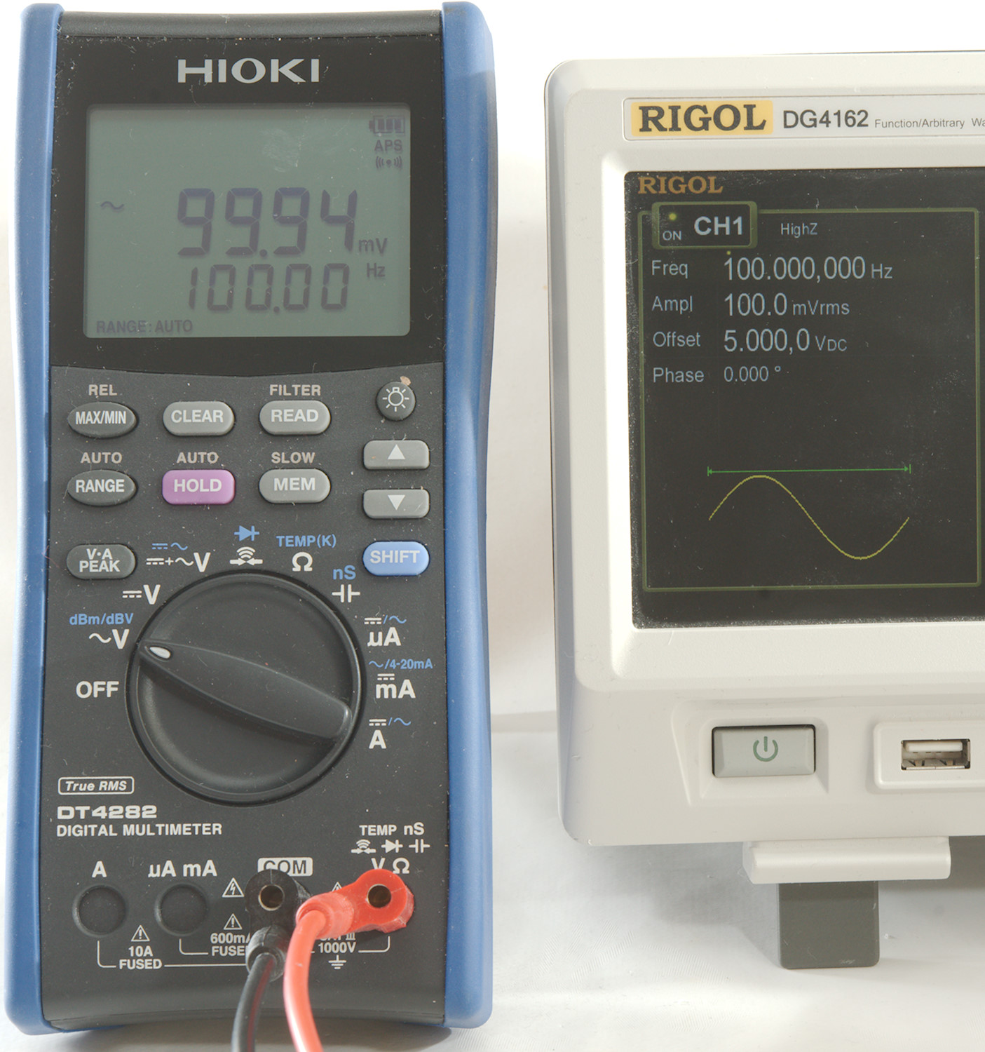
This meter with a capacitor at the input has no problems with it. It can also do it when using the AC/DC input, this checks for both AC and DC, before selecting a usable range.
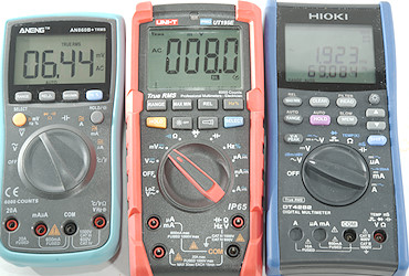
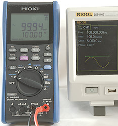
AC frequency
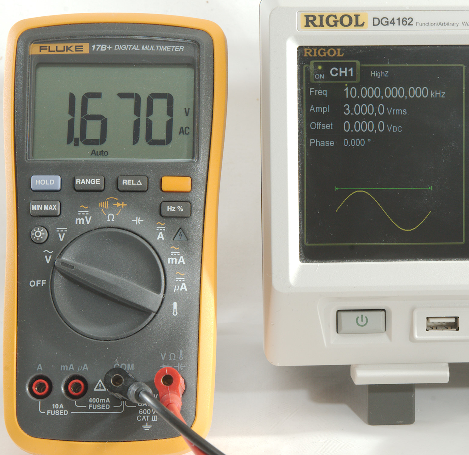
Multimeters are as a minimum designed for handling 50 and 60Hz AC voltage
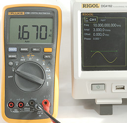
This means that they may not show the correct value at higher frequencies, for cheap meters they will often show wrong values above about 2kHz, this meter here is not that bad, but 10kHz is too much.

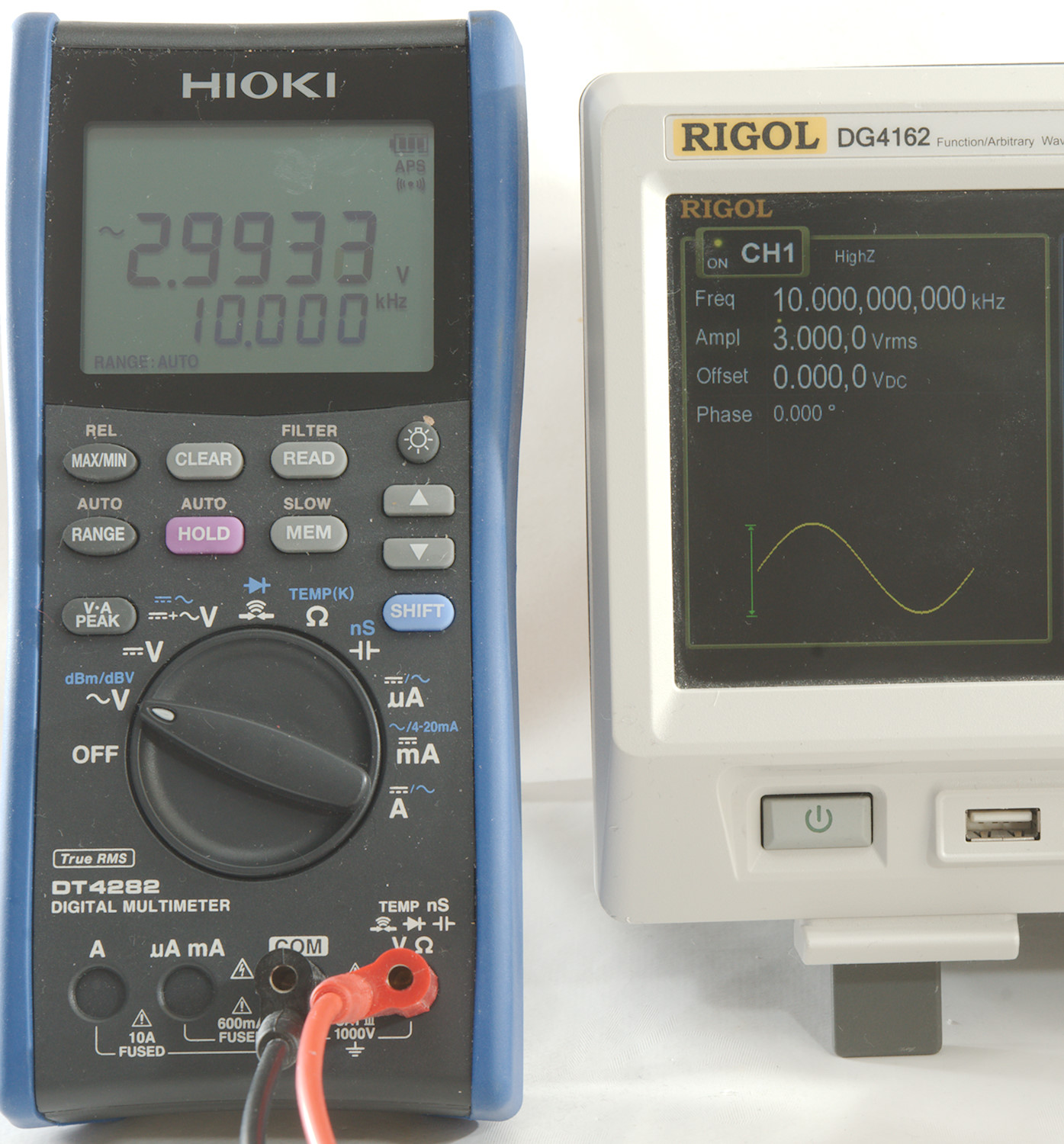
A better meter can handle 10kHz perfectly
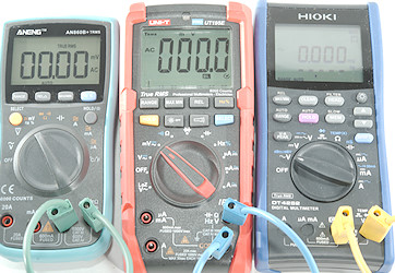
True RMS, crest factor and waveform
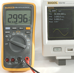
The sinus from above can be handled by just about any multimeter (Some meters cannot handle low AC voltage).
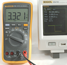
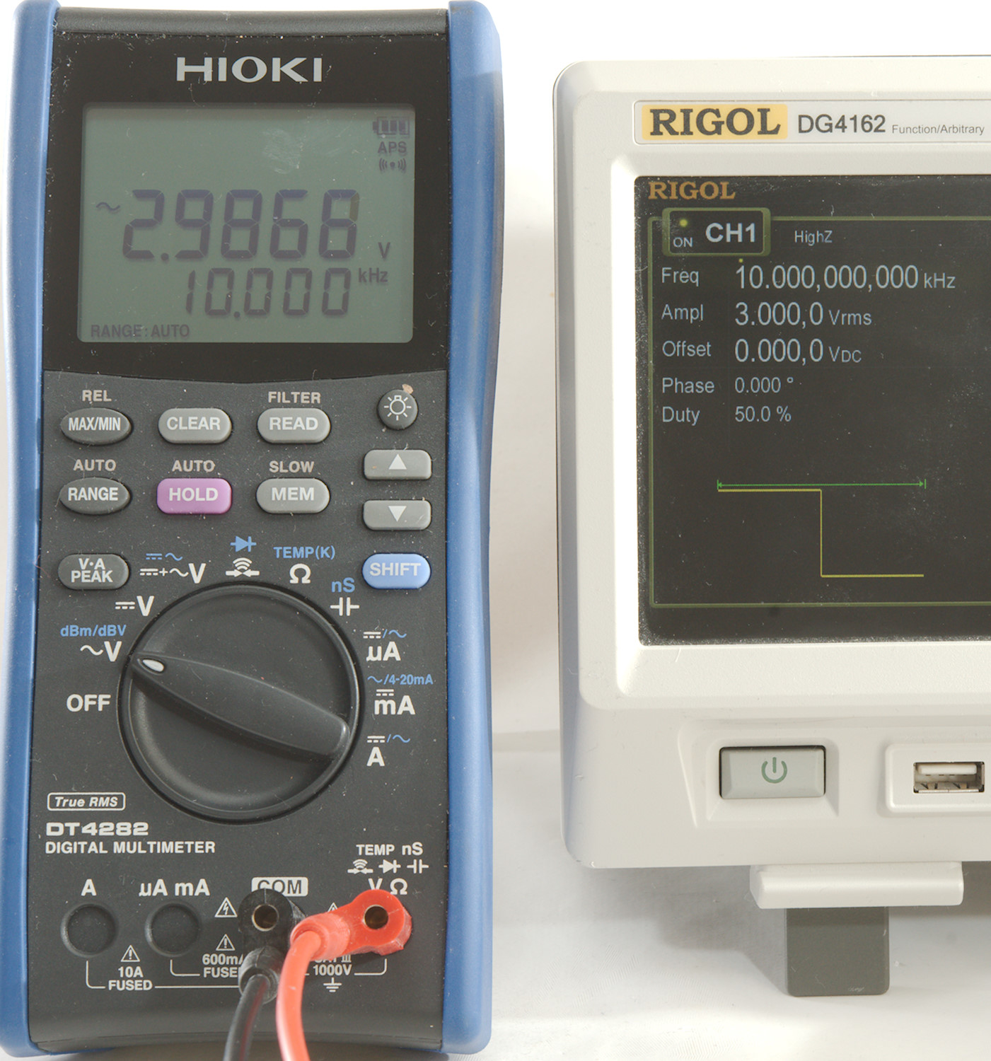
But AC comes in many shapes, this square wave is also 3V RMS, but the meter shows 3.321V.
This has something to do with how meters work and how voltage is defined, lets take the definition first: AC voltage must generate same power in a resistor as a similar DC voltage, i.e. 3V AC must heat a resistor exactly the same as 3V DC. Calculating power is sqr(U)/R or U*U/R. What you need to do in praxis is to square the voltage, calculate an average (mean) value and take the square root (s-m-r but always written the other way r-m-s or RMS).
This is a bit tricky to do in hardware, instead it has been common to just rectify the AC, take the average value and scale it. This works perfectly fine for one waveform and the required waveform is sinus, this is the reason the meter shows correct for sinus, but not for other waveforms.
One more advanced meters (and in new cheap multimeter chips) there is some circuit to do the square, mean and root and we get a "True RMS" meter that can handle all waveforms as long as they stay within some limits.

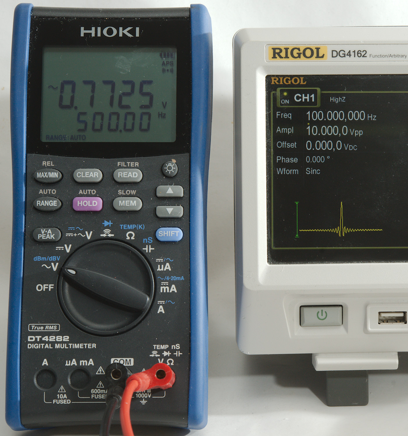
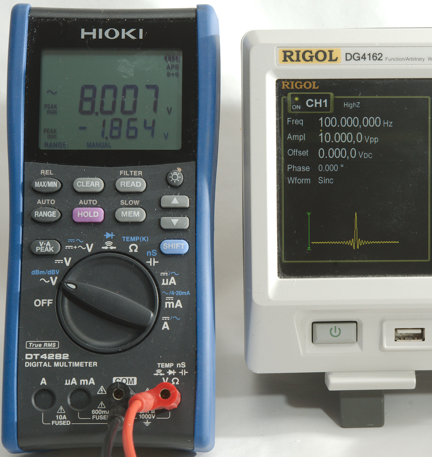
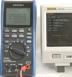
Lets try a more special waveform. The meter says it is 0.7725 volt, but I have asked for 10V from the generator, of course the generator is peak-peak voltage.
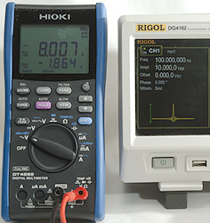
This meter can capture peak voltages at a very fast rate and it shows the voltage goes from +8.007V to -1.864, this is much closer to the requested 10V, but can I trust the meter values? There is a couple of factors to that:
- Frequency, do the waveform contain higher frequencies than the meter can handle.
- Is the peak the value out of range
- Crest factor
If the meter is in a 1V range it can show 0.77V rms, but what happens when the input voltage hits 8V, do it make the rms calculation correctly or will the peak value just be ignored?
The datasheet value for this is called crest factor and it may vary with the input voltage, i.e. at the low end of the range it may be fairly high (I have meters with up to 10), in the middle of the range it may be 2-3 and at the top of the range 1.5 to 2. This crest factor is just the peak value divided by the rms value, in this case 8.007/0.7725 -> 10.365 for the positive peak. This is a very high value. A sinus has a crest factor of 1.41 (sqrt(2)).
At the top of the highest AC range the crest factor is usual 1.5, this means a 1000V AC range can handle a peak of 1500V. Meters with 600VAC or 700VAC as maximum and 1000VDC maximum is also designed for crest factor 1.5 (or maybe slightly below) because that matches the 1000V as maximum input voltage.
Peak AC pitfall
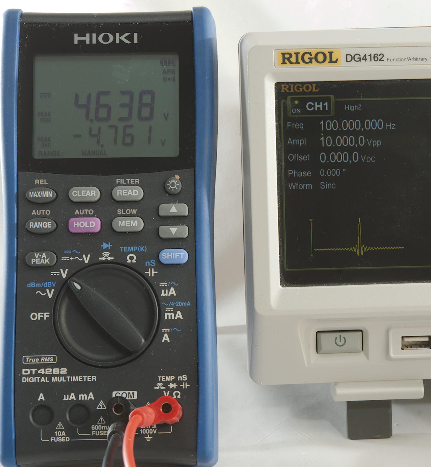
How correct these maximum and minimum values are, depends on how you look at them. The meter has a capacitor at the input, i.e. the +/- values are not absolute DC values, but peaks from the average DC voltage.
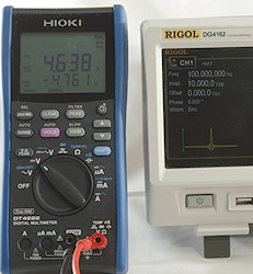
If I switch the meter to DC the values will be different, this time it is the maximum and minimum compared to 0V, not to average DC level.
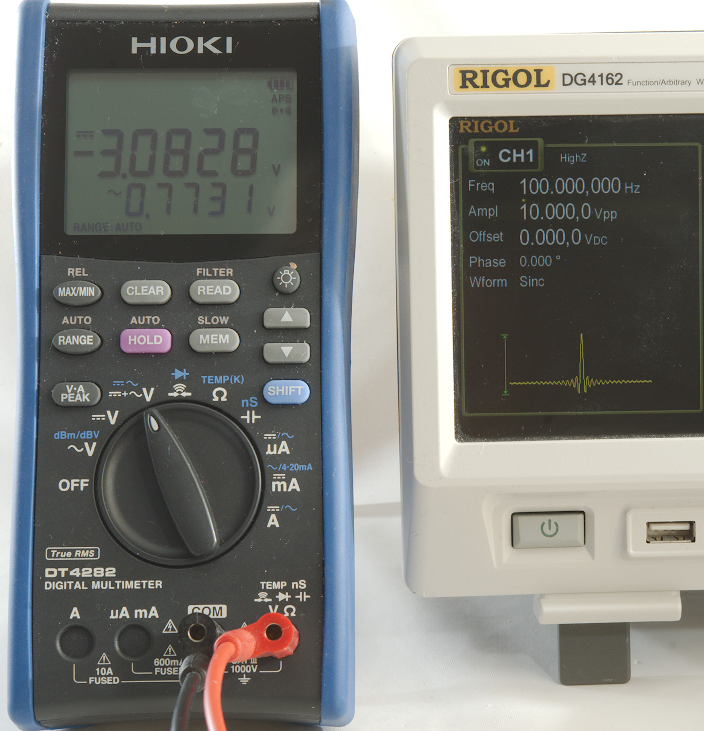
The actual DC voltage is around -3.1 volt.
The values do not completely match up, probably because I am using a signal with a very high crest factor and using different ranges on the meters (AC with capacitor, DC and AC/DC input is not the same).

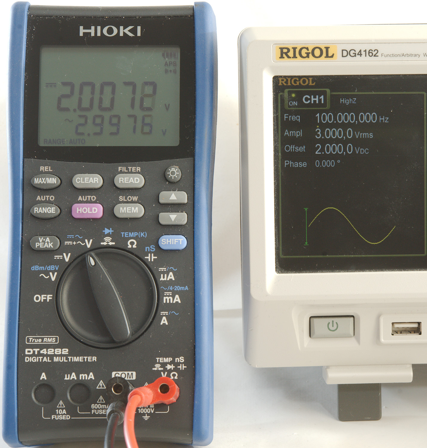
Lets try again, this time with a sinus and no high frequency contents. Voltage are 3VAC (4.24Vpeak) and 2VDC. When using the input with capacitor the peak function show the peak of the sinus and ignores the DC.
Using the AC+DC mode will include the DC, this means the values from above is shifted 2V due to the DC contents.
On meters without a capacitor on the AC input the peak function will often work fine for DC.
RMS on DC ranges
Multimeters use average on DC ranges, also meters with "True RMS".
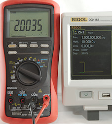
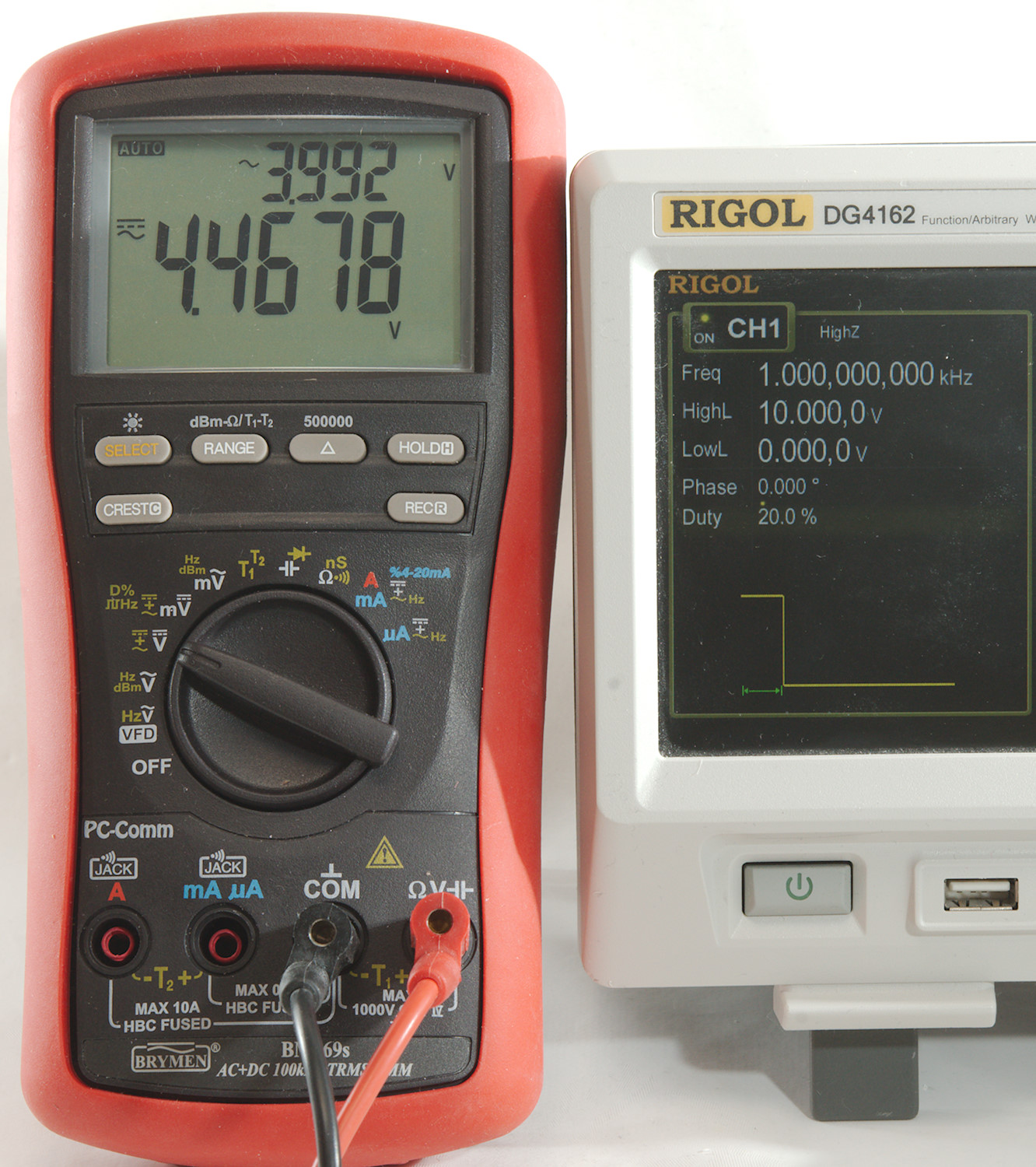
Here is a 20% and 50% square wave and as can be seen the meter show 2 and 5 volt, i.e. 20% and 50% of the 10 volt. This is an average value the rns value is higher.
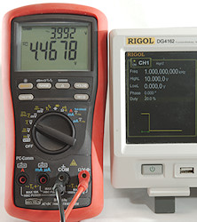
Because this meter also has a AC+DC function I can do a rms calculation on the waveform and get the higher value.
When calculating power this can be useful, the 20% of the time with 10V will make heat as 4.47V, not as 2V in a resistor
High voltage
Multimeter are usual rated for 600 to 1000V, but there exist higher voltages, how can they be measured?
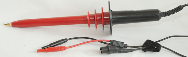
Here is a high voltage probe for use with a multimeter, this probe can be used for DC and low frequency AC, but not on high voltage mains, it is strictly for isolated fairly low power high voltage supplies. This probe is rated for 20kVAC and 40kVDC with 3% accuracy, it will divide voltage by 1000. (It is a BK PR-28A)
There is a big caveat when using (storing) this type of probe, it must be kept in a fairly dry environment, any moisture on the inside or outside and it gets dangerous to use.
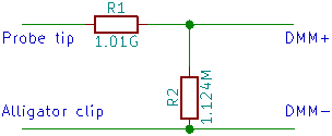
The design is very simple, it is just two resistors. R1 is probably a series of smaller resistors. Probes for higher frequencies will have capacitors in parallel with the resistors.
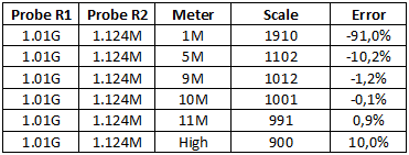
Doing some math on the resistors in parallel with a multimeter shows that you have to be careful with input range on meter (Many multimeters are high impedance in mV and 11Mohm on the lowest voltage range and 10.1Mohm on the next voltage range). There is also some meters with lower impedance in AC ranges.
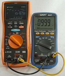
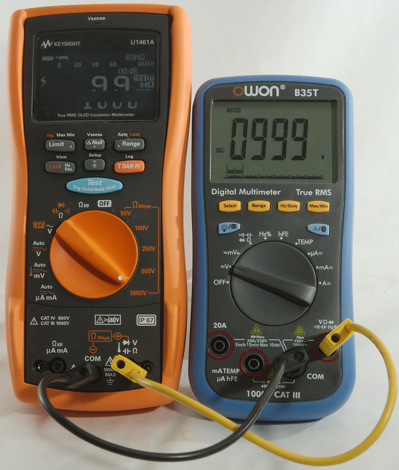
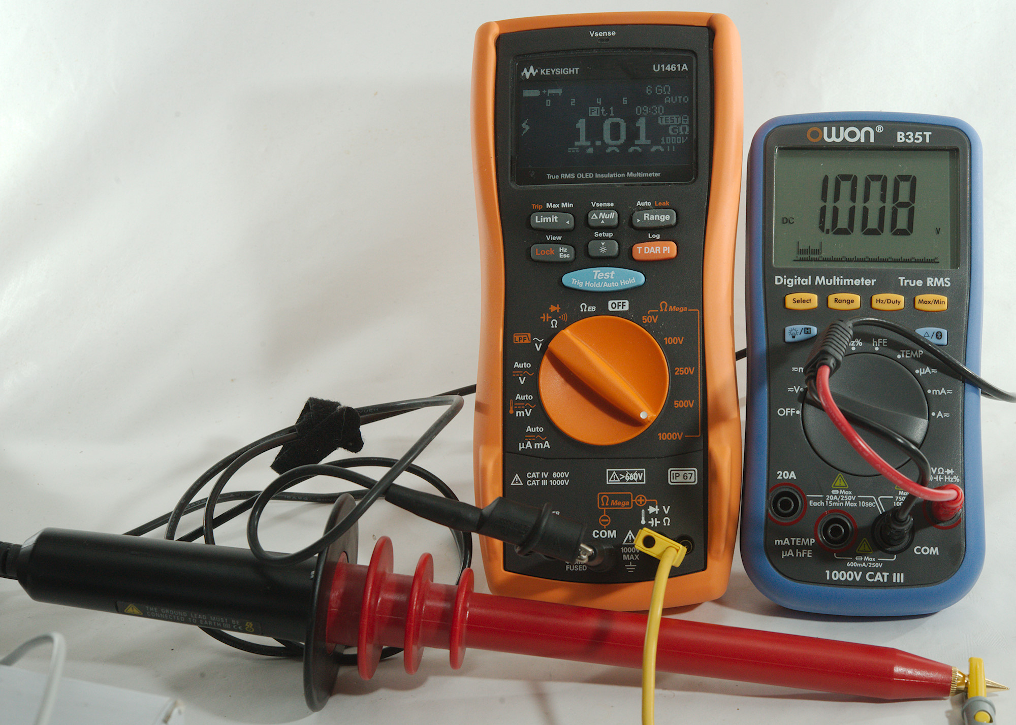
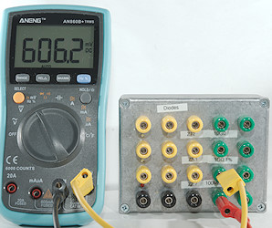
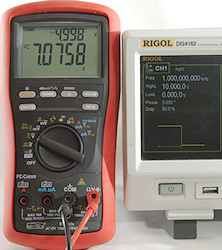
I use a insulation meter to generate 1000V and as can be seen on the blue meter is is fairly precise.
The display on the U1461A is not faulty, the black bar is due to the scanning.

With the HV probe and the meter in the low voltage range, the meter show too high value. It is below 1% wrong, this means it is not really a problem.
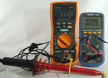
Selecting next higher voltage range and the value looks better. The main issue here is not so much a 1% error, but more that the meter reading will change with range.
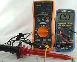
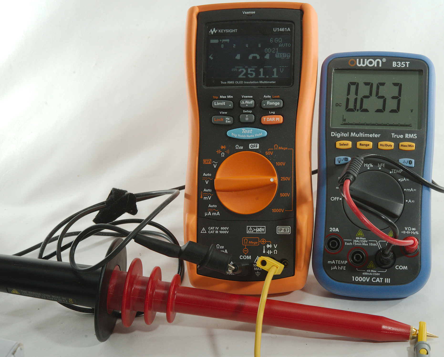
Lets try a lower voltage, here I use 250V and the meter shows about 0.253V, this is fine.
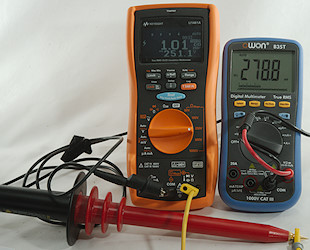
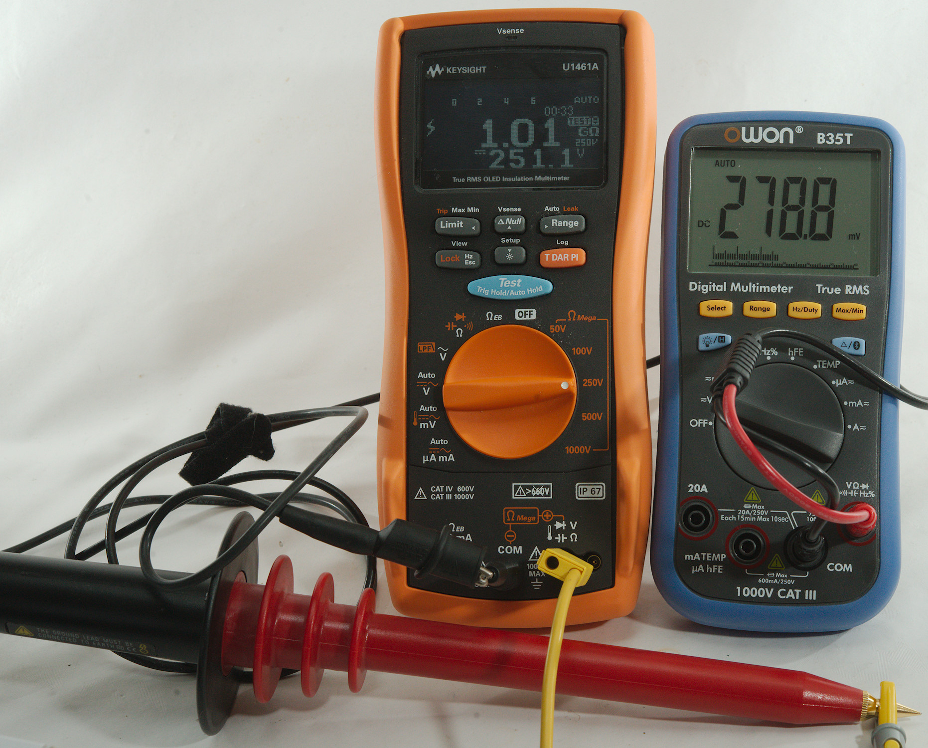
But if I let it auto range into mV with high input impedance it is about 10% out. It is very seldom this will be a problem on handheld meters, in most cases the two lowest volt ranges will be what is needed and not the mV range.
Conclusion
It is easy to measure voltage, but there are some pitfalls. With DC it is not that much, but AC is a very big area and there are much more to look out for.
Notes
Multimeter and pulsed DC current (PWM)
Tolerance specifications for multimeters
Multimeters and current measurements
Multimeters and thermocouples