USB power information
This article is about usb power and all the different standards.
PC connector history
I will start with a short history of the connectors that was used before usb.
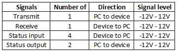
Printer, LPT port (Centronics)
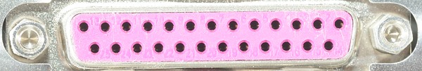
At the time the PC was first designed by IBM the most used connectors on printers was a 36 way Centronics connector with half the pin connect to ground and the other half for data and signaling (Using half the wires for ground is good practice for high speed cables). This connector is rather large and the PC got a 25 pin d-sub connector instead with a lot fewer ground connections.
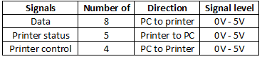
Communication was mostly from computer to printer, but with the status input pin it was possible to receive data on the computer and at a fairly decent speed (I.e. much faster than RS232). Later on the data pins got bidirectional, making it possible to use the port for external disks.
All signals was fairly low level, i.e. it was not possible to draw much power (<1mA), but a few devices succeeded in doing it. I know of hardware keys that were used to lock software to a specific computer.
Serial, COM port (RS232)
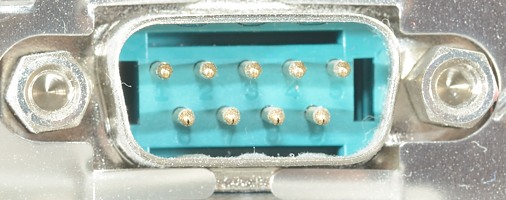
Most low speed peripheral communication was done with RS232, it is/was a very simple interface that could be done with as little as 3 wires or as much as 25 wires. For the PC it was cut down to a maximum of 9 wires and a smaller d-sub connector.
One data input and one data output and a couple of status pins. Due to the "high" voltage levels special chips was nearly always required to drive these signals. It has been fairly standard in many small devices (Like mouse and magnet card readers) to use the status signals for power, it is possible to draw 5-10mA.
Today the serial port is still used, but often at TTL level (i.e. 5 volt) and with a usb converter that gives 5 volt DC together with Rx and Tx signals (Outside the device it will look like a regular usb device and on the PC it is a virtual com port).
Keyboard port
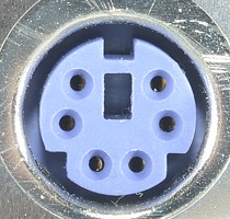
Because the keyboard needed power, IBM could not use RS232 (At that time it was not possible to make a keyboard with low enough power consumption), instead they made another connector with power and data connections. First a 5 pin DIN connector, then a 6 pin mini DIN connectors.
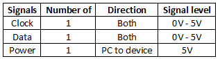
There is two way communication and power, this could have been the future communication standard, but there was some serious limits on data speed, especially from the PC to the keyboard, it was (mostly) limited to sending lamps (Num, caps, scroll lock) on/off messages.
It has been used for a lot of low speed input devices like barcode scanners, magnet card readers, advanced joysticks, numeric keyboards, often designed to be place between the regular keyboard and the PC.
The reason for placing all these devices on the keyboard connector was the power, it could deliver 200-300mA at 5 volt and for some devices they would also work without any software installation.
Mouse port
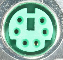
When PC got graphical operating systems a mouse was needed, IBM added one more connector for this.
The connector was exactly the same as the keyboard connector, except the data received here was assumed to be from a mouse.
Joystick/game port
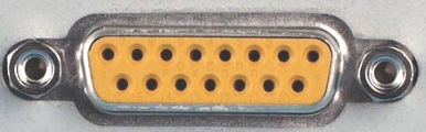
To enhance the possibility for games on the PC IBM made an adapter card with a joystick port, it used a 15 pin sub-d connector.
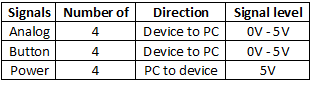
The analog input was not real analog to digital converters, but part of a timer circuit where the potmeter in the joystick would adjust the time of the circuit. The button was simple digital inputs. This means this port had no output. This connector had signals for two simple joysticks, but a Y-cable was needed for that.
It was possible to draw significant power from this connector, up to about 700mA, but without any outputs there was not much use for this power.
At a later date at least some game ports got serial (MIDI, playing musical notes) in/out.
Summary
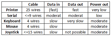
A lot of different connectors, but none that can do fast data both ways and supply power. All connectors are only designed for one device each or at most two devices.
Even the fast data rate would be very slow by todays standard.
USB history, very simplified and focused on power
A lot of companies decided to make a universal serial bus that could replace the above mix of connectors and at the same time provide better support for peripherals. That meant fast data both ways and power, but also the possibility to use hubs, i.e. connect many devices to a single port. The slowest data rate was about the same speed as the fastest data rate for the legacy connectors, but even from the start USB supported 10 times that speed.
To make the bus useable on laptops there had to be some restriction on power usage. I will not get into all the details, but the general rule was and still is that any device connected to a normal usb port must not draw more than 100mA, if it want to use more power it must talk with the computer about it first.
This requirement was ignored by many manufacturers, mostly for various toys that could be connected to a usb port for power (It was cheaper than included a mains adapter), but usb harddisks has also ignored it.
Then China and later EU decided that mobile phones must be charged from usb, that way it was possible to save a lot of resources on power adapters (It has not really worked out that way). That did give the different phone manufacturers a slight problem, usb could only supply 2.5 watt and charging a phone battery is fairly slow at that power level.
To handle that many manufacturers started to code the usb signals from their power supply, this way a phone could recognize it was connected to a power supply and increase charge speed above standard usb power levels.
The designers of the usb saw that and decided to make some coding in the usb standard that could be used (Battery charging), it was very simple and is widely adapted today, it could deliver 5-7 watt, but the requirements for power has raised higher and manufacturers are still using their own codes for higher power levels.
A few of the big chip manufactures decided to make their own addition to usb for increased power, they are usual very simple to implement and some of them can support very high power levels.
Again the designers of usb decided to improve the usb with higher power levels (Power delivery), it is available today and can deliver enough power to charge a laptop (60-100 watt). The problem with this standard is the complexity, it need special chips to work, can only work with USB-C connectors and it cannot be done with a few microprocessor outputs and resistors.
Usb connectors
There are many different usb connectors, one reason is the way usb was designed from the start:
Computer device uses a A socket that connects with a A cable/connector.
Peripheral device uses a B socket that connects with a B cable/connector.
Then mini and soon after micro was added, both needed A and B connectors and sockets.
Then there was the problem with devices that could both be a computer and a peripheral (Like phones and cameras). To handle this "on the go" or OTG was added to the usb standard and the AB socket was defined (Mini-AB and Micro-AB).
To handle the ever increasing need for speed, some wires was added to the cable and a new connectors was again needed, this was called SuperSpeed. These new connectors were only defined for full size usb and micro usb, not for mini. Some of the connectors stayed compatible with the old connectors, some not (The problem is the B plug).
And the latest addition is the USB-C socket and connector, no A and B, it is the same plug at both ends.
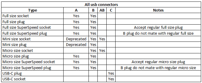
Here I have listed all usb connectors, the total is 23 different ones.
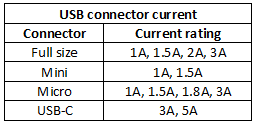
All connectors has a current rating, with usb you can get connectors in different quality with different current rating. I checked mouser (Big electronic part supplier) for usb connectors and found the above ratings.
As can be seen not all connectors are rated for high current charging, but the only cable where this is controlled is USB-C.
Using too high current in a connector can be a fire risk, but with the small power levels here it is mostly about damaging the connections, this will give higher resistance. I.e. the cable may work fine at first, but may soon be rather bad.
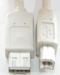
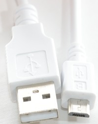
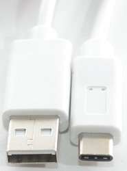
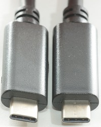
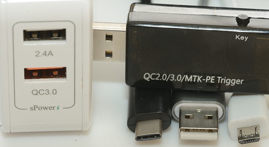
Some common usb cables. The first is the classic full size A to B connector, the next one is full size A to micro B, this is the one used to charge most phones today. For equipment with USB-C connector the full size A to USB-C is often used. The last cable is USB-C to USB-C, looking at the cable it is not possible to see if it is usb 2.0, usb 3.0 and if it has a chip and maybe allows 5A charging.
How to get faster charging
There are many "technologies" for increasing the charge speed, but in the end it all gets down to getting as much power as possible to the battery and keeping the battery as cool as possible.
To increase power it is possible to either increase current or voltage and some do it both ways and increase both current and voltage. Each method has advantages and disadvantages:
Increase current
This is easy, simply make the charger more powerful, devices that do not know about this will just work as they have always done.
To tell devices about more current, the usual way is to code the two data lines with some resistors, there is, of course, more than one standard.
The disadvantage with more current is more loses in the cable and connectors, i.e. a part of the extra power does not even reach the phone. There is also a current limit on the connectors (See above).
Increase voltage
Because power is the product of voltage and current, another way to get more power is to increase the voltage. The first problem with this is that anything that is not prepared for this will probably fry, i.e. it cannot just be available, but will require that the device send a special message to the charger to enable the increased voltage.
This method is not really used on its own, see next entry.
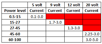
Increase current and voltage
For the newer fast charge methods this is often used, this makes it possible to use the usb cable to the limit. With old usb connectors usual 15-35 watt (More is possible) and with USB-C up to 100W.
A typical phone fast charge will be in the 15W to 18W range today.
Decrease voltage, increase current
This will not give the maximal amount of power (The battery may not be able to handle it anyway), but is used to keep the device as cool as possible when charging.
The idea is that the battery is connected directly to the usb connector and the charger supplies the current directly to the battery, this means no heat from the charging circuits in the device. The device will control the charge by sending commands to the charger and can disconnect the battery at any time.
This is useful for smaller devices, where heat is a problem, but limits the charge current to 1.5A to 5A range depending on connectors. Because the voltage of a single LiIon cell is from 3 to 4.2 volt, these chargers need to go below 5 volt.
To use higher current a proprietary connector can be used (See VOOC below).
Other tricks
Current and voltage are the only parameters to adjust when wanting more power, but fast charging is also temperature depend, this opens of for a few tricks.
Do not use a linear regulator, it will development a lot of heat, especially if charging with high current.
Use a switcher regulator and design it for high efficiency (This can be side stepped completely by decreasing voltage).
Using a thermo sensor in the device, it is possible to adjust the charge current depending on temperature.
Placing the charging electronic as far away as possible from the battery can keep the battery a bit cooler during charge.
Low resistance, keeping the resistance low means less heat. This can be done with thick wires, multiple connections to the battery and high current batteries.
Batteries and fast charging
What about the batteries, can any battery be used for fast charging and can the current just be increased?
The answer is no to both. Batteries must be types that are designed for fast charging and there is a reason for specifying fast charge time to 60% (or something near that).
The very high charge speed is only possible at lower charge state in the battery, when the battery is more filled it is not possible to charge nearly as fast.
This also opens for another trick: Report battery full before it is, the charging will be considerable faster if the battery is report full a few percent below 100%
What about batteries and lifetime when fast charging? I do not have any hard data, but some conjecture:
1) Heat wears the battery down, i.e. if the battery gets very hot during charge the lifetime will be shorter. This is the reason for low voltage charging, it tries to limit the heat from the internal charge circuits in the phone.
2) Fast charging is usual only active at low battery charge state, i.e. you get the battery filled to 50% or 70% fast, then the charger slows down. Because batteries are not as sensitive to high current charging at low charge level, this means the wear will be fairly limited.
3) Most phones and pads have a temperature sensor and will reduce charge rate or turn charging off when the battery warms up.
4) It is always the phone or pad that controls the charge rate, never the charger and the phone is supposed to know the battery (Except if you replace it with a cheap substitute).
5) When batteries are worn down, always replace with batteries that is guaranteed to handle the charge speed.
Overview of "standards"
Here I have collected most usb power standards I know about.
USB battery charging (BC 1.2), DCP

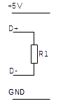
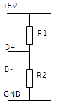
This coding only requires a single resistor and it can be zero ohm, i.e. a short. Nearly all 1A chargers uses this standard and most equipment can understand it.
It is allowed to draw more than 1.5A from this standard, if the connectors are rated for it and the power supply can deliver. For higher current the device must monitor the voltage and reduce current if the voltage drops too much.
USB power delivery
The first version of this standard was built to be as universal as possible. That meant bidirectional communication superimposed on the power pins. In a later revision the support for old usb connectors was removed and only support for USB-C remains, this also means the communication was limited to the CC pins. Data rate 300kbaud at 1.1 volt, i.e. requires special transmitters and receivers, these drives will be included in chips designed for USB-C, but is a bit difficult to do with ordinary microcontrollers. Up to 5V 3A can be done with resistors, above that the cable needs a chip. Maximum power is 20V 5A, i.e. 100W
Without a chip the power is limited to 15W, with a chip the voltage can be increased and more power draw.
USB connector type C
This is the most advanced usb connector to date, it has 24 pins. The cable can have a chip inside with manufacturer, current handling capability and other information.
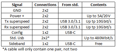
Above is a list of the wires in the USB-C cable. It is possible to make USB 2.0 cables in USB-C, they will be missing all the 10Gbit/s and sideband wires.
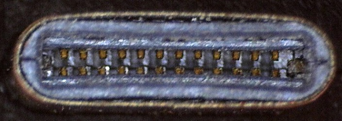
Here all the 24 pins can be seen.
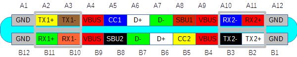
The layout is symmetrical with the four corner pins being gnd (0 volt), the next two pins is superSpeed/gigabit, then 1 pin for Vcc (+5V). The next pin is configuration and sideband and the center pins are old usb 2.0 (note: A cable only has one usb 2.0 connections, per definition on the A side).
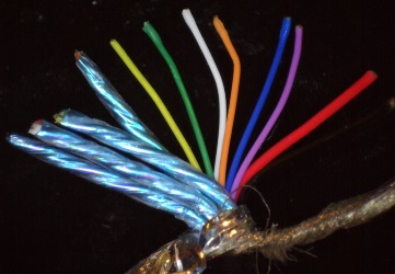
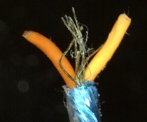
The wires in a cable, the 4 twisted and shielded pairs are gigabit connections, red and black (It is to the right of the red wire) is power, the other wires are one standard usb (White/green) and the 2 config and 2 sideband connections. In this cable the colors do not completely follow the color layout above.
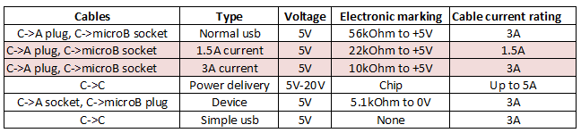
USB-C uses a resistor to define maximum current draw, for USB-C to USB-C cables this resistor will be in the charger, not in the cable. Cable from USB-C to older usb connectors will have a resistor and to avoid overloading weak chargers it is only allowed to be "standard usb", not the 1.5A or 3A marking. For current above 3A the cable must have a chip and it must approve the current.
Devices must have a 5.1kOhm resistor to 0V (or gnd), this signals that it uses power and cannot deliver power.
All these resistors are placed on the CC pins.
The USB-C cable is not limited to usb communication, devices can talk with the chip in the cable and be allowed to use the wires for other purposes (Like: DisplayPort and Thunderbolt 3). This repurpose is done on a wire basis, i.e. it is possible to have power, usb and DisplayPort in the same cable at the same time. For Thunderbolt 3 both the usb cable and the device at the other end must support it, for other repurpose schemes I do not know if the cable must directly support it.
Apple
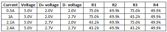
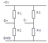
Apple was first to do their own coding, they started with 0.5A and slowly increased current as devices need more charging power. Today it looks like they have retired the 0.5A and 1A setting and uses USB DCP instead. The 2.1A and 2.4A are still used.
Sony

Sony uses same type of coding, but with other resistor values. I have not seen any current specifications for this one.
Samsung

They also used the resistor coding, but made it a bit more simple.
Qualcomm Quick Charge 2.0 A
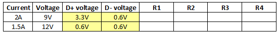
QC can increase voltage, to avoid accidental doing that it requires some special voltage on the usb data pins and it is the device that wishes fast charging that must provide the voltage, then the charger will switch to a higher voltage on the usb. This standard is fairly easy to implement with any microprocessor.
The currents I have listed are typical values from chargers.
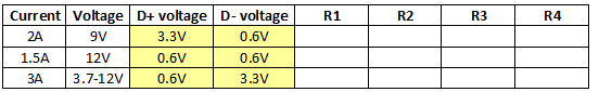
Qualcomm Quick Charge 2.0 B
For higher power requirements the QC standard can deliver up to 20 volt, the actual current is supposed to depend on the connectors used. This charger is very rare.
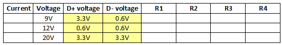
Qualcomm Quick Charge 3.0
The QC3 standard did not increase the power levels, but added the possibility to fine tune the voltage. The idea is to adjust the voltage to minimum power loss in the phone charging circuit, this way the battery is cooler and can be charged a bit faster.
The currents I have listed are typical values from chargers, the 3A is only possible at lower voltages.
Pump express by Mediatek

This looks like a low cost fast charging system. It does not use the data pins for communication.
This version can reduce output voltage, allowing the phone to directly connect the battery to the charger, i.e. disabling its own charge circuits. This means the phone will be cooler.
The voltage can be adjusted from 5V down to about 3.6V in 0.2V steps.
The usb charger does not need any extra chips to support this charging, the mains switcher can do it directly. The phone communicates with it by pulsing the current. This means the minimum charge current must be 0.5A or it is not possible to communicate reliable.
Pump express+ by Mediatek

Same low cost system as the one without + in the name, but this version work for voltages above 5 volt, it uses the same stepping codes as "Pump Express".
The actual voltages are 5V, 7V, 9V and 12V
Pump express+ by Mediatek V1.1

Same low cost system as above, it looks like the + got updated with lower voltages.
The actual voltages are: 3.6V, 3.8V, 4.0V, 4.2V, 4.4V, 4.6V, 4.8V, 5V, 7V, 9V, 12V.
Pump express+ by Mediatek V2.0

Same idea as the other pump express protocols, but this version work for a larger voltage range and with direct selection of voltage. The codes and communication rate has changed. It looks like chargers supporting this is also supposed to support the old type.
The voltage can be adjust from 5V and up to 20V in 0.5V steps, this time with 5 bit codes to directly select the voltage. The current is in the 2A to 3A range, but will be limited if the cable resistance is high.
Pump express by Mediatek V3.0

I do not have much data on this yet. It is supposed to use USB-C connector and USB-C communication, with the possibility to adjust the voltage in very small steps in the 3V to 6V range and up to 5A charge current.
The idea is to bypass the charge circuit in the phone/pad and charge the battery directly (Controlled from the phone/pad) and avoid any heat from the phones charge circuit.
Samsung AFC, Adaptive Fast Charging

This system uses the D- pin for communication. This system allows selected voltage in 1V steps and current in 0.15A steps.
Hisilicon FCP, Fast Charger Protocol
Output voltage range 5V to 12V, use the D- line for bidirectional serial communication at 3.3V. The communication is used for AFC, FCP and SCP protocols.
Support by FP6600Q and FP6601Q ic's, that also supports QC2 and QC3.
Hisilicon AFC, Advanced Fast Charger Protocol
Output voltage range 5V to 20V with current from 0.75A to 3A, use the D- line for bidirectional serial communication?
Huawei FCP, Fast Charging Protocol

This is based on the Hisilicon FCP, i.e. D- is used for communication and the protocol allows for 3-20V and up to 25.5W (Note: The power, not the current is adjusted), it is possible to read the chargers capabilities and other information with this protocol.
Huawei SCP, Smart Charging Protocol

This also uses communication on D-, but has much more elaborate communication, this means reading of the actual output and charger brand and model.
The system is for low voltage charging with high current with very fine voltage and current adjustment steps. The maximum current is higher than allowed by usb, i.e. practical chargers will either be limited in current or use other connectors.
Spreadtrum Fast Charge Protocol
I do not have much information about this.
Output voltage range 5V to 20V and supported by the GL883A-10 and GL883A-20 chips (They support just about any charging protocol).
VOOC Flash Charging
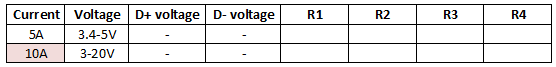
This is not really usb charging, it requires special 7 pin usb micro connectors. I.e. only a VOOC cable will work.
With equipment that supports it and the special cables it is possible to charge with 5A, voltage stays at or rather below 5V.
The protocol supports up to 20V and 10A with very fine voltage and current adjustment, but the connectors do probably not support that.
Dash Charging

This is based on VOOC charging, but uses a USB-C connector to the phone, the current is reduced to 4A.
The USB-A connector is special and only the correct connector will enable fast charging, i.e. only a Dash cable will work.
iPower, iSmart, AiPower, VoltIQ, PowerIQ, sPower, etc.
Many chargers and power banks are marked with something like the above, they all means the same: The charger has a chip that automatically select the best coding for fast charging at 5 volt. I.e. what I call "auto" in my list of charger coding.
This chip will usual select between Apple (Either 2.4A or 2.1A), Samsung or DCP, making the charge port versatile.
All these are 5 volt charging, but with more current than standard usb.
Most QuickCharge will not include this functionality, but there exist a few that can, this will not make QC or any other charging mode faster, it just means the QC socket will have optimal charge rate for more devices, not only for QC devices.
How to handle all the standards
It can be rather confusing to find the best charger for a phone or other devices.
Most standards use the original usb data pins, they can be used with ANY usb data cable (Thick short cables preferred), but will not work with charge only cables.
Smartphones and other computing devices will usual check the coding, i.e. the charger must provide the correct one. Most, if not all, phone brands supports DCP, but they do not tell what code they need to charge faster. The easiest way to handle that it to get a charger with auto coding, they contain a chip that will (usual) say the charger is for Apple, Samsung or DCP, depending on what the device is expecting. This means any device will get at least DCP coding (1A charging), but often a 2A code.
It is possible for device to recognize more than one coding and I have seen chips supporting it.
Some newer (2015+) high end smartphones, except Apple will often support Quick Charge, this usual means 50% charge in half an hour (The first 50% to 70%, filling the battery takes longer). There are also other brands with incompatible fast charge solutions as can be seen above.
With USB-C it is possible to use a simple resistor based current coding or a chip, for now it looks like the resistor is used in normal chargers. There is nothing preventing QuickCharge to work on USB-C (except the usb standard forbid it).
Chargers, power banks, toys, etc. do seldom check the coding, they will just draw power, sometimes adjusted depending on voltage.
For most high speed charging the data pins are used, this means some "power only" usb cables will not work, a phone will refuse to charge or use lowest charge speed.
Conclusion
Charging a usb device is supposed to be simple, just plug it in and it charges, but to get the optimal charging speed can be rather difficult. It requires knowledge about what standard the device supports and if the charger can support the same standard and this is not always announced.
Until now I have not seen any standards that are incompatible of each other, i.e. where you risk damaging the device, the only risk is no charging or slow charging.
Also remember that any usb "charger" only provides power, the actual charging is always controlled from the phone or pad.
For charging with higher currents it is best to use short cables with thick wires (Lower AWG is thicker), for charger methods that increases voltage this is not as important.
I wonder if all these specialized and proprietary charge solutions will disappear when USB-C gets more common. Getting high current and/or voltage from USB-C is more complicated, but for phones and pads this is not much of a problem. The problem is for other stuff that uses/delivers usb power.
Notes
For many of the charge protocols the listed current is not a fixed value, but will change depending on conditions, i.e. some chargers may be able to supply more current, some less.
To check the actual current and voltage on a device it is possible to use a usb voltmeter, but this will usual affect the device, i.e. it may reduce the charge rate due to the larger resistance in the cable (This is mostly a problem at 5V and below).
Some of the protocols listed are probably the same protocol, just with different names.
If anybody has more information about these fast charge protocols or other fast charge protocols, please send me the information.