How do I test a usb power supply/charger/power bank
I test different equipment with usb outputs:
- Chargers
- Mains to usb power supplies/chargers
- Power banks
I uses a couple of different methodes to test them, this article will show what type of test I do.
Equipment
First a look on the equipment I uses.
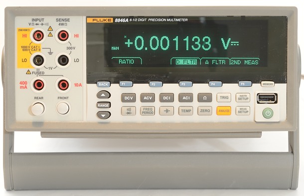
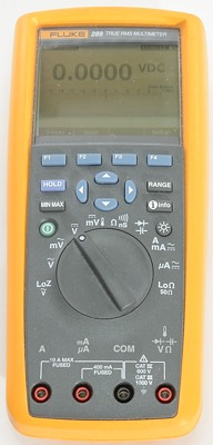
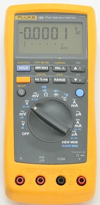
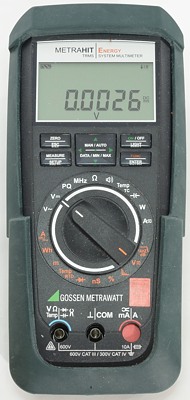
I must be able to measure and log the result to a computer, for this I uses a couple of Fluke DMM and a Gossen DMM. The Gossen has one special feature that is important when checking mains powered equipment, it can measure power/watt. With AC power it is not enough to measure voltage and current and then mulitply them, it is also necessary to measure a "power factor". This feature is not very common on DMM's.
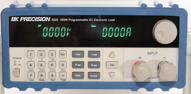
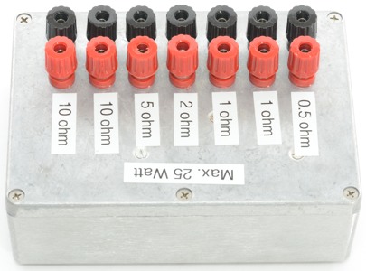
To do any test, I need to put a load on the usb output, for this I can use either a electronic load or resistors. The electronic load is usual busy doing battery tests, making the resistors the most used load.
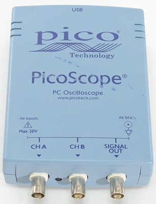
To see how clean the output is, I am using a oscilliscope. For my usage a usb version is very useful, this means I get the curves directly on the computer.
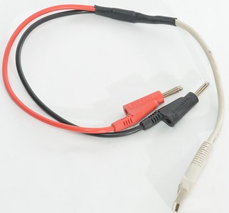
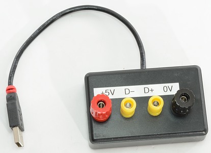
None of the above equipment can be connected directly to a usb connector, for this I have made a special cable and a breakout box. The cable can be used for load tests, but the breakout box is needed when I want to check what standard the usb power supply is following. I do have boxes for all 3 sizes of USB connectors, the mini and micro is mostly used when I need to supply current to a charger.
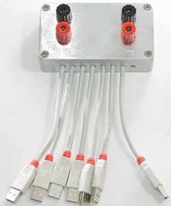
When testing a usb power supply with many outputs a single usb cable is not enough. With the above box I can connect to all outputs at once (This only works if they are running on the same regulator inside the power supply) and get a fairly low resistance, making high current tests possible.
At higher currents I nearly always uses the electronic load, except for noise measurement that is done with a resistor load.
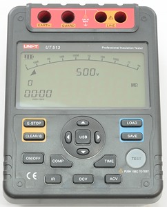
For mains powered equipment I can also use the mega ohm meter or insulation tester. It will apply a high voltage and measure the resistance. What I am interested in is not the resistance, but if the insulation breaks down.
Load sweep test
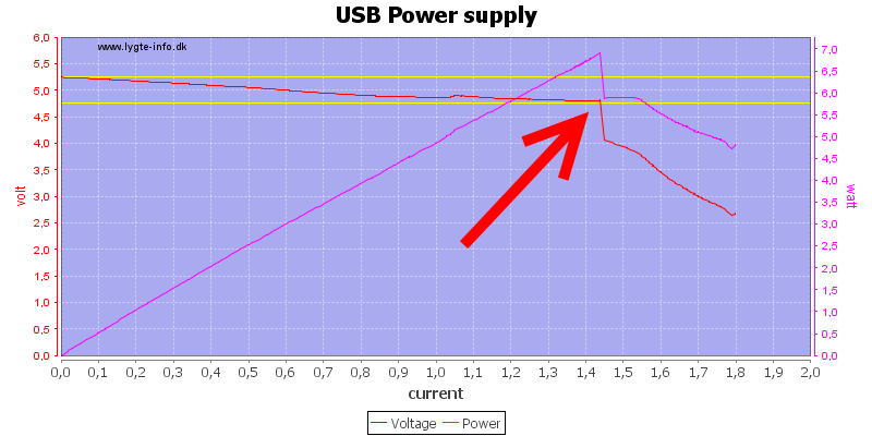
This test is used to get an idea about the performance of the usb power supply, the test only takes a few minutes, but requires the electronic load.
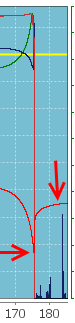
The yellow lines shows the USB voltage limit, chargers does only need to stay above the lower limit up to 0.5A, but equipment might not charge when the voltage is below that limit.
The red line show the voltage as the current increases, because the test is done in a few minutes there is no gurantee that the voltage and current can be sustained. To check sustained current I also do a load test.
For battery powered equipment the maximum voltage and current might depend on how much charge there is in the battery.
Load test
For mains powered equipment I run this test for one hour and only shows the output voltage and current:
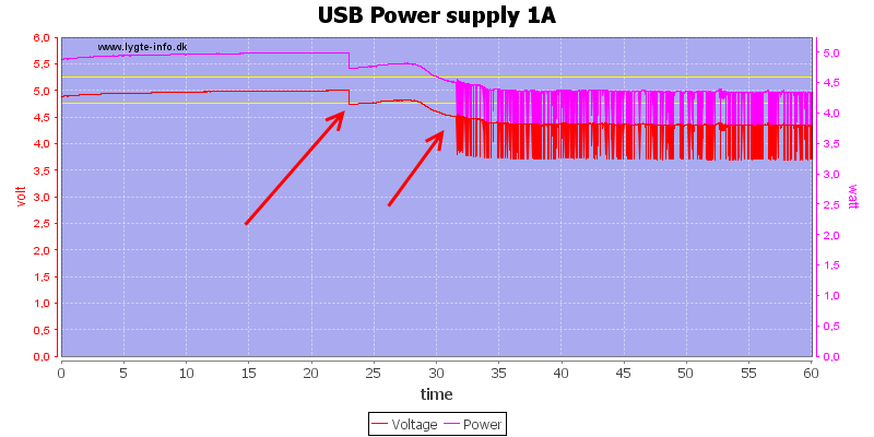
This power supply could not sustain a 1A load for more than 23 minutes and 10 minutes later it starts doing some silly stuff on the output.
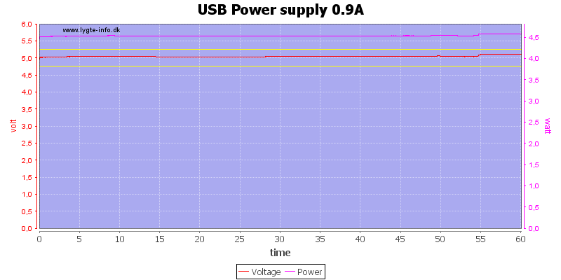
But reducing the load to 0.9A makes it possible to sustain it for one hour and probably also longer.
.png)
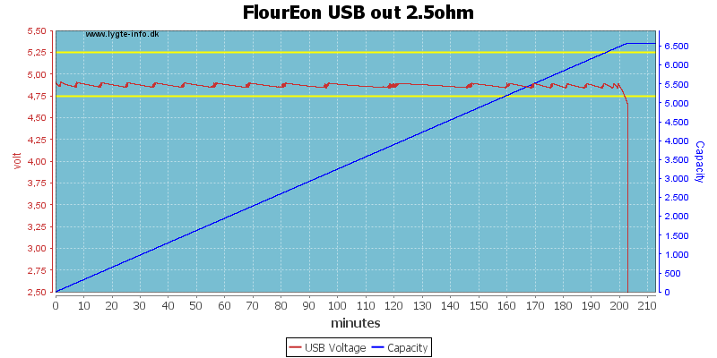
For battery powered equipment I run the test until the battery is empty and the chart will show data for both the battery voltage/current and for the usb voltage. I will specify the usb current in the text, it can also be calculated from ohms law: voltage/resistance->current and with usb voltage of about 5 volt the current in the above chart will be 5/12 -> 0.417A
The USB voltage will always be the red line that starts at around 5 volt, the battery voltage will start just above 4 or 8 volt, depending on number of batteries.
While the battery voltage will decrease during discharge, the battery current will increase, to keep the output power constant.
The dark blue line is efficiency, it has to be as high as possible or the unit will waste power. This value will depend on battery charge state and current draw, a good unit can have 0.8 (80%) or better.
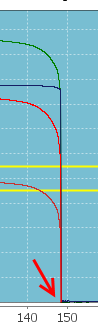
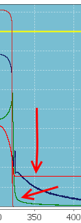
It is very interesting to see what happends when the battery is empty. Above I have collected 3 different ways to end the discharge.
- The discharge does not stop, but runs the battery down to a very low voltage or until the protection in the battery kicks in. This is the worst termination.
- The discharge slows down (Green line does not go to zero), to keep the battery voltage at the minimum voltage.
- The discharge stops completely and the battery voltage will increase again, this is the best termination.
This termination must happen at just about 3 volt. If the termination happens below 3 volt, be careful to select batteries that can take it (Panasonic 2900/3100/3400 mAh can work down to 2.5 volt without damage).
In some power banks I do not have access to the battery and can only do test of the usb output. Here it is important that the box turns off when the battery is empty, it must not drop slowly in voltage.
These boxes have usual a specified capacity (mAh), this capacity is not how much it can deliver out, but the capacity of the used battery. Do not expect more than about 70% of the specified capacity when I test the usb output.
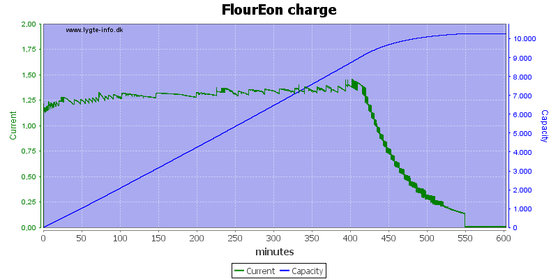
With no access to the battery, charging will also only be measured from the outside. Here the capacity will be very close to the real battery capacity.
Oscilloscope trace
Using a oscilliscope to look at the output voltage, does also reveal something about the charger. I do these tests at the rated load or if the power supply cannot supply that much at the maximum it can supply.
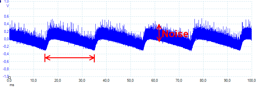
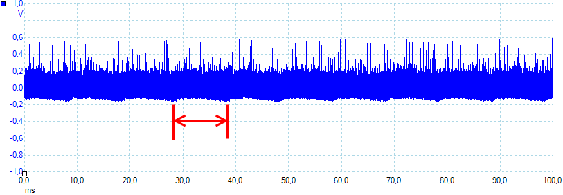
This trace has a lot of noise, that is the thick trace and the spikes. The more regular waveform repeating at a 20 ms interval says that this charger is using a single diode as rectifier and has a bad stabilization.
This usb power supply has better stabilization, but has enough ripple in the output that it is possible to see the 10 ms intervals, that means a bridge rectifier. The noise is even worse than the above example.
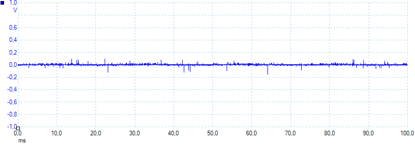
Very good stablization and low noise, it is not possible to see what kind of rectifier this power supply uses.
High voltage test
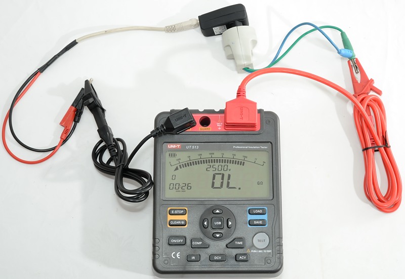
For this test I connect the two mains wires together and all the usb output wires together, then measure the resistance between mains and usb.
This resistance will be very high, but on some equipment the insulation will break down due to the voltage, this must not happen! Mains equipment without any earth connection must be able to handle 5000 volt DC (Safety standard says 3000 V AC or 4243 V DC for 230VAC supply), between mains and low volt side.
With this test it is very important to keep away from the wires when the test voltage is on!
Capacity
Usual usb power banks specify battery capacity, not output capacity. This is a bit misleading, but it is fairly easy to get an idea about the output capacity.
In the table below I have listed the rated capacity (or battery capacity) and possible output capacity depending on efficiency. A well designed power bank will have between 80% and 90% in efficiency, it will be lower at higher loads.
I.e. a battery bank specied with 10000mAh will usual be able to deliver between 5920 and 6660mAh on the usb port.
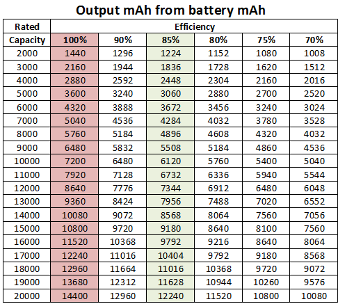
The math used: rated_capacity*3.6/5*efficiency -> expected_output_capacity
USB coding
The usb standard prohibits using power, without getting it approved from the computer. There are some very good reason for that, but a lot of equipment has ignored this and drawn power anyway.
To stay within the usb standard with the equipment, some companies has added a special coding to their charger and their equipment will only charger if this coding is present. Later on the usb standard has been modified to include a simple coding that signals that this is a charger. The usb standard has also added some more complex codings that allows data ports to signal that they can be used for charging.
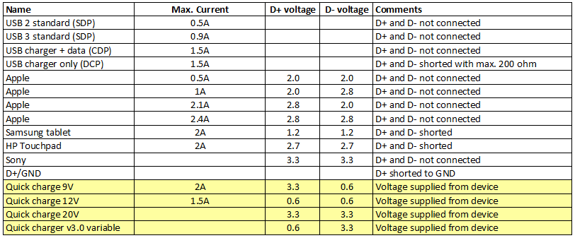
The above table lists some of the codings I could find, for a more elaborate explanation see my article about usb power.