ADS1115 ADC library
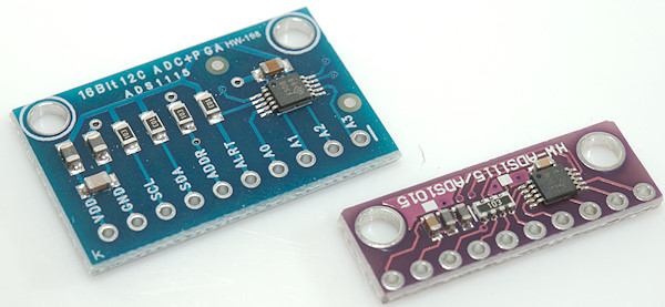
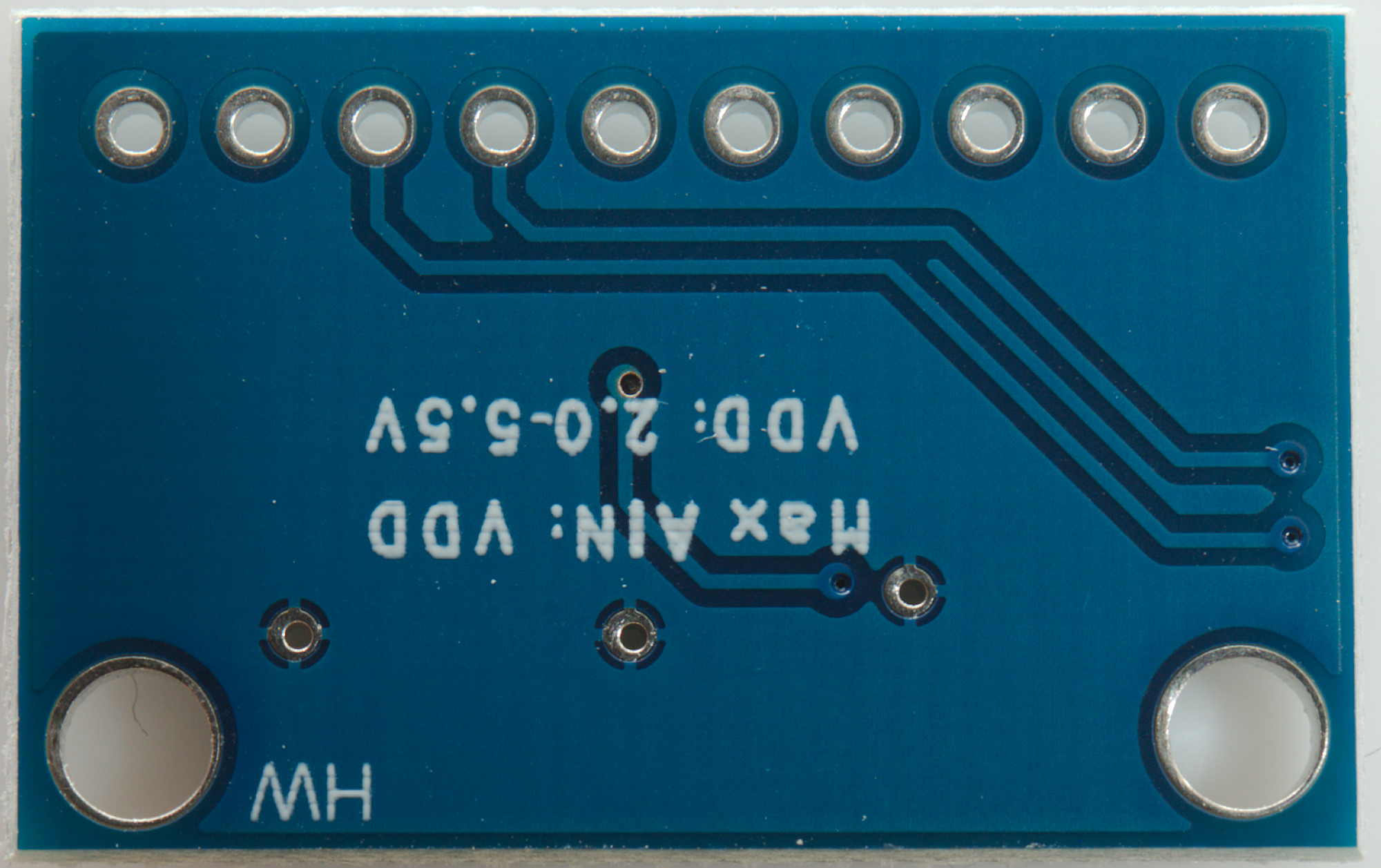
For a couple of projects I needed better precision than the build-in ADC in Mega processors could provide, looking a bit around I found this chip and module, it is cheap and has 15 bit resolution. The chip has a build in reference, making it fairly stable when the Arduino supply voltage varies.
I looked at some libraries, but they where not exactly what I wanted, as a result I wrote my own library.
Contents
ADS1115 ADC library
ADS1x15 functions and resolution
Requirements
The library functions
Includes
Constants
All functions
Constructors
Setting conversion speed
Single conversion
Single conversion with auto scale
Background conversion
Multiple conversions
Scaling
Connection Arduino and ADS1115 module
Arduino Nano
Arduino ProMicro
Conclusion
Notes and software download
ADS1x15 functions and resolution

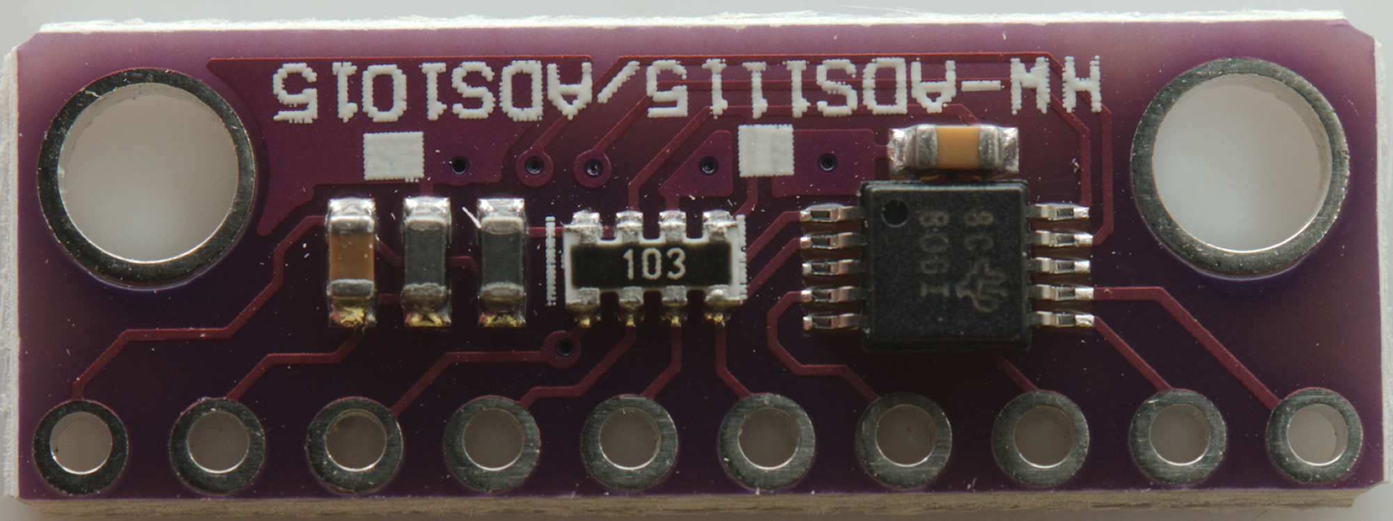
The module and chip exist with two different chip configurations:
- ADS1015: 12 bit resolution, I will not be using or supporting this, the price different to the ADS1115 is very small.
- ADS1115: 16 bit resolution
They both have four inputs and can read from 0V to VCC on each input, they can also read the difference between two inputs, but only some specific input combinations.
Reading the specifications shows that the 12/16 bit is stretching it a bit, they are 11/15 bit resolution and then a sign. The sign can only be used when doing differential readings, i.e. reading the difference between two inputs, then one input can be above or below the other input, i.e. + or -.
The converter is fairly slow, at the fastest rate it can do 860 conversion each second (for ADS1115) at the slowest 8 conversions each second. The advantage with the slow conversion is low noise, i.e. successive readings will be fairly similar and not jump up and down without doing a lot of filtering before the ADC.
The chip has a PGA, that is short for programmable gain amplifier and means it is possible to select input range, this makes it possible to use the 11/15 bit resolution for lower signal levels. The lowest range is 0.256V for a 32767 reading or about 7.8uV for each step. This means it is possible to get at least 10000 in resolution anywhere in the 0.1V to VCC range.
As usual with CMOS chips the inputs can handle up to 10mA if the voltage goes above VCC or below GND, this means a resistor in series with the input can protect against some over voltage, but there is a caveat and that is the input impedance, it varies from 3Mohm to 100Mohm for single ended and 0.7Mohm to 22Mohm for differential and with 32767 steps in resolution a series resistor will usually affect the result a bit.
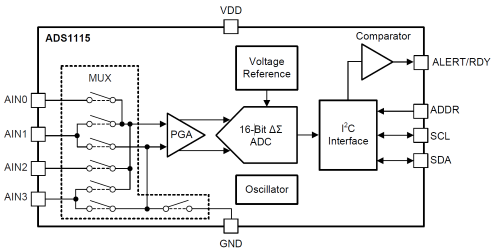
A simplified schematic of the chip.
Requirements
My initial list of requirements for the library was:
- Must not block the processor while converting.
- Must support all the gain settings.
- Automatic or manual gain selection.
- Can use any conversion speed.
- Can convert multiple channels without a lot of calls.
Later on I added a few more points:
- Can do average or filtering of multiple readings.
- Can do calibration/mapping of values, I needed this code somewhere and decided to put it here.
The library support a couple of very different operating modes as describes below.
The library functions
Includes
Code:
#include <Wire.h>
#include <ADS1115.h>
The library is named after the chip and it needs the wire library to work.
Constants
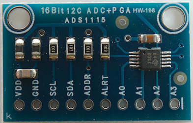
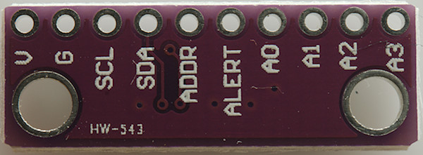
The ADS1115 can have four different I2C addresses, the lowest one is with the address pin connected to ground and I have defined this as a constant (It is also the default address for the module when the ADDR pin is unconnected), to get the other addesses add 1, 2 or 3:
- ADS1115ADDRESS: ADDR pin connected to GND
- ADS1115ADDRESS+1: ADDR pin connected to VCC
- ADS1115ADDRESS+2: ADDR pin connected to SDA
- ADS1115ADDRESS+3: ADDR pin connected to SCL
Next comes channel selection, either single ended or differential.
- ADS1115_CHANNEL0: Single ended input on channel 0
- ADS1115_CHANNEL1: Single ended input on channel 1
- ADS1115_CHANNEL2: Single ended input on channel 2
- ADS1115_CHANNEL3: Single ended input on channel 3
- ADS1115_CHANNEL01: Differential input on channel 0 and 1
- ADS1115_CHANNEL03: Differential input on channel 0 and 3
- ADS1115_CHANNEL13: Differential input on channel 1 and 3
- ADS1115_CHANNEL23: Differential input on channel 2 and 3
It is always possible to select either single ended or differential input, it will not affect gain or conversion speed, but differential may return negative values.
Notice that input 3 can be common for any of the other inputs, the only other differential input is 0 and 1.
The input sensitivity, i.e. the PGA setting. These are named after the maximum value in millivolt:
- ADS1115_RANGE_0256: Maximum scale is 0.256V
- ADS1115_RANGE_0512: Maximum scale is 0.512V
- ADS1115_RANGE_1024: Maximum scale is 1.024V
- ADS1115_RANGE_2048: Maximum scale is 2.048V
- ADS1115_RANGE_4096: Maximum scale is 4.096V, but will be lower in a 3.3V system
- ADS1115_RANGE_6144: Maximum scale is 6.144V, but input will be limited by VCC,
The conversion speed:
- ADS1115_SPEED_8SPS: Slowest speed with up to 8 conversions each second, this is also the range with least noise.
- ADS1115_SPEED_16SPS
- ADS1115_SPEED_32SPS
- ADS1115_SPEED_64SPS
- ADS1115_SPEED_128SPS
- ADS1115_SPEED_250SPS
- ADS1115_SPEED_475SPS
- ADS1115_SPEED_860SPS: Fastest speed with up to 860 conversions each second.
All functions
Constructors
There are a couple of classes, depending on what is needed.
Code:
ADS1115 adc;
ADS1115 adc(ADS1115ADDRESS);
ADS1115 adc(ADS1115ADDRESS+1);
ADS1115 adc(ADS1115ADDRESS+2);
ADS1115 adc(ADS1115ADDRESS+3);
The first two is the same. The address is controlled by:
- Addr pin is connected to GND: Use no parameters or ADS1115ADDRESS
- Addr pin is connected to VDD: Use ADS1115ADDRESS+1
- Addr pin is connected to SDA: Use ADS1115ADDRESS+2
- Addr pin is connected to SCL: Use ADS1115ADDRESS+3
Code:
ADS1115Scanner adc;
ADS1115Scanner adc(ADS1115ADDRESS);
ADS1115Scanner adc(ADS1115ADDRESS+1);
ADS1115Scanner adc(ADS1115ADDRESS+2);
ADS1115Scanner adc(ADS1115ADDRESS+3);
With this constructor it is possible to do batch conversion and averages, this class will reserve a sample buffer for the total number of samples it needs to collect. 10 samples for two channels is 40 bytes (10*2*sizeof(int)).
Code:
ADS1115MapInt scale;
ADS1115MapInt scale(int lowValue,int lowReference,int  highValue,int highReference);
ADS1115MapLong scale;
ADS1115MapLong scale(int lowValue,long lowReference,int highValue,long highReference);
ADS1115MapFloat scale;
ADS1115MapFloat scale(int lowValue,float lowReference,int highValue,float highReference);
These are independent classes when doing calibration, they need a low and high value with both the real value and the ADC value, then they will scale the actual reading. The actual definition of the reference points can be done either in the constructor or at a later time.
Setting conversion speed
Code:
void setSpeed(byte speed);
Setting the conversion speed is done with this call, it will be used for all the following conversion, until a new call is made.
The speed is set when starting the conversion, changing this value during a conversion will first take effect from the next conversion. The default settings is 64SPS.
Code:
#include <Wire.h>
#include <ADS1115.h>

ADS1115 adc;

void setup() {
    Wire.begin();
    adc.setSpeed(ADS1115_SPEED_16SPS);
}
Here the speed is defined at startup and not changed later.
Single conversion
Code:
int adc.convert(byte channel,byte range);
Do a single conversion and wait for the result, channel and sensitivity can be selected for each call.
Code:
#include <Wire.h>
#include <ADS1115.h>

ADS1115 adc;

void setup() {
    Wire.begin();
    adc.setSpeed(ADS1115_SPEED_16SPS);
}

void loop() {
    int value=adc.convert(ADS1115_CHANNEL0,ADS1115_RANGE_0512);
}
Define the speed initially and then convert each round in loop, with 16SPS the conversion time will be about 0.06 second, where the Arduino will not do anything else.
Single conversion with auto scale
Code:
float convertAutoScale(byte channel);
float convertAutoScale(byte channel,byte samples);
This call will do a single conversion with 6.144V sensitivity, check the actual result and then one or more conversions with the best range for the value (When the lasts parameter is present and larger than one multiple conversion will be done and the average will be returned.
If only one value is required and the actual value is for the 6.144V range, the value will be returned without doing more conversions.
The change points for ranges are: 0.19V, 0.38V, 0.75V, 1.5V, 3V or about 75% of range, this leaves some headroom for changing values. It will not change range when sampling the values for the average calculation.
Code:
#include <Wire.h>
#include <ADS1115.h>

ADS1115 adc;
void setup() {
    Wire.begin();
    adc.setSpeed(ADS1115_SPEED_16SPS);
}

void loop() {
    double value=adc.convertAutoScale(ADS1115_CHANNEL0);
    double value=adc.convertAutoScale(ADS1115_CHANNEL0,5);
}
The first conversion will either by 0.06s or 0.13s, depending on input voltage. The second conversion will use 0.37s, i.e. it will do 6 readings, one for the scale and 5 for the average.
Background conversion
Code:
void start(byte channel,byte range);
boolean ready();
int read();
For background conversion 3 functions are used: one to start the conversion, one to check the state and lastly one to read the result.
Calling read before the conversion is done will stall the read until conversion is finished.
Code:
#include <Wire.h>
#include <ADS1115.h>

ADS1115 adc;
int value=0;

void setup() {
    Wire.begin();
    adc.setSpeed(ADS1115_SPEED_16SPS);
    adc.start(ADS1115_CHANNEL0,ADS1115_RANGE_0512);
}

void loop() {
    if (adc.ready()) {
        value=adc.read();
        adc.start(ADS1115_CHANNEL0,ADS1115_RANGE_0512);// Start next conversion
    }
}
The conversion is started in the setup and then checked in the loop, when a conversion is ready the result is read and a new conversion is
started. This routine will not block the loop, but only need a short time (About 0.5ms) to check if the conversion is ready.
Multiple conversions
When needing more than one channel and/or calculating average for multiple values, this class moves the job to the background.
Code:
void addChannel(byte channel,byte range);
void clearChannels();
void setSamples(byte samples);
void start();
void update();
boolean ready();
int readAverage(byte channel);
int readFilter(byte channel);
int *readSamples(byte channel);
For this function to work update() must be called frequently, preferable more often than the conversion speed.
First a list of desired input channels are defined, this can both be single ended and differential, there is space for up to 4 entries. Then averaging is define (setSamples), it can be one when none is required.
Starting the conversion will start with the first defined channel, then the second, when the all defined channels are read, it will start over until the required number of samples are read.
The ready function will report ready when all channels and samples are read, the results will be stored in a array. There are two functions to read the values, one that will return the average and another that will remove the highest and lowest value before calculating the average (This means samples must be 3 or higher). It is also possible to get a pointer to the data for a channel (readSamples). The channel specified in readAverage/readFilter/readSamples is not the ADC channel, but the index from addChannel, i.e. first addChannel will be 0.
Code:
#include <Wire.h>
#include <ADS1115.h>

ADS1115Scanner adc;
int value0=0;
int value13=0;

void setup() {
    Wire.begin();
    adc.setSpeed(ADS1115_SPEED_16SPS);
    adc.addChannel(ADS1115_CHANNEL0,ADS1115_RANGE_0512);
    adc.addChannel(ADS1115_CHANNEL13,ADS1115_RANGE_0256);
    adc.setSamples(5);
    adc.start();
}

void loop() {
    adc.update();
    if (adc.ready()) {
        value0=adc.readAverage(0);
        value13=adc.readAverage(1);
        adc.start();
    }
}
Start by defining sample speed and channels, then start the conversion. In loop call update frequently and when ready is reported the values can be read for all channels. Finally restart the conversion.
Scaling
It is often required that the result be scaled to a more sensible range than 0..32767 or for the auto ranging function to something other than volts. This requires a single expression to do and when doing it in integer you have to be careful not to get overflow. To keep this under control I made some classes for it, they store the two points and has the single expression to do the scaling.
These routines can be used for all conversions, except convertAutoScale.
The formula used is:
ScaleValue = ((readValue - lowValue) * (highReference - lowReference)) / (highValue - lowValue) + lowReference;
Code:
void setRef(int lowValue,int/long/float lowReference,int highValue,int/long/float highReference);
int/long/float scale(int value);
Store the two reference points and scale one value at a time. The "value" is the values from the ADC1115 and the "reference" is the desired output values at that reading. High and low must be paired values:
Low: ADS1115 reads 6709 and desired output is 1.23
High: ADS1115 read 20521 and desired output is 23.54
Set reference: scale.setRef(6709,1.23,20521,23.54);
Now any call to scale.scale() will linearly convert readings from the ADS1115 into floating point values, following the above checkpoints. The conversion is not limited to the defined range, but will work over the full output range of the ADS1115.
Code:
ADS1115ScaleInt scale;
ADS1115ScaleLong scale;
ADS1115ScaleFloat scale;

scale.setRef(lowValue,lowReference,highValue,highReference);
scaledValue=scale.scale(value);
Define only the classes needed, this depends on the desired data type of the final value. Each channel may needs it own class.
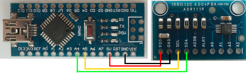
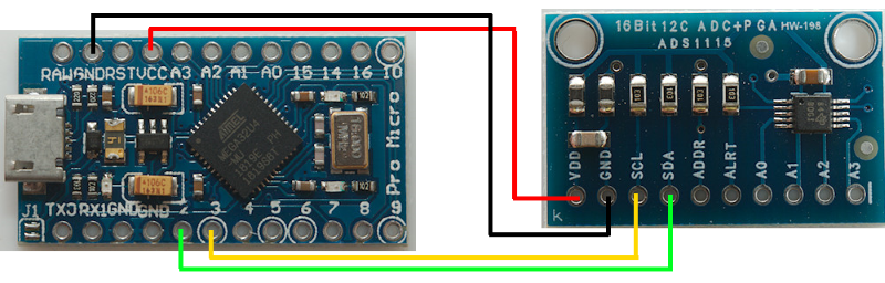
Connection Arduino and ADS1115 module
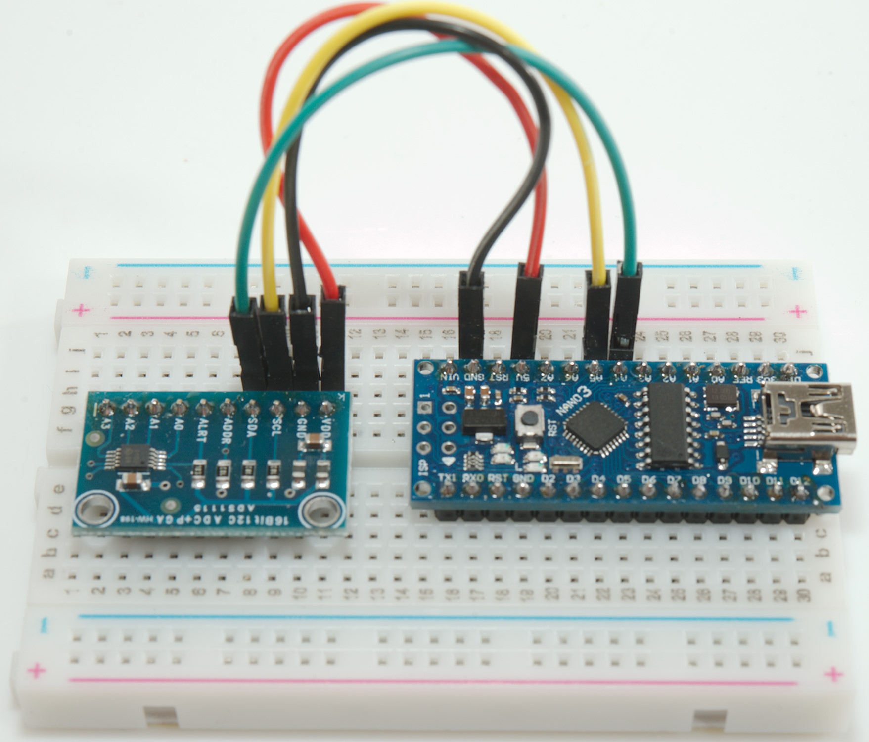
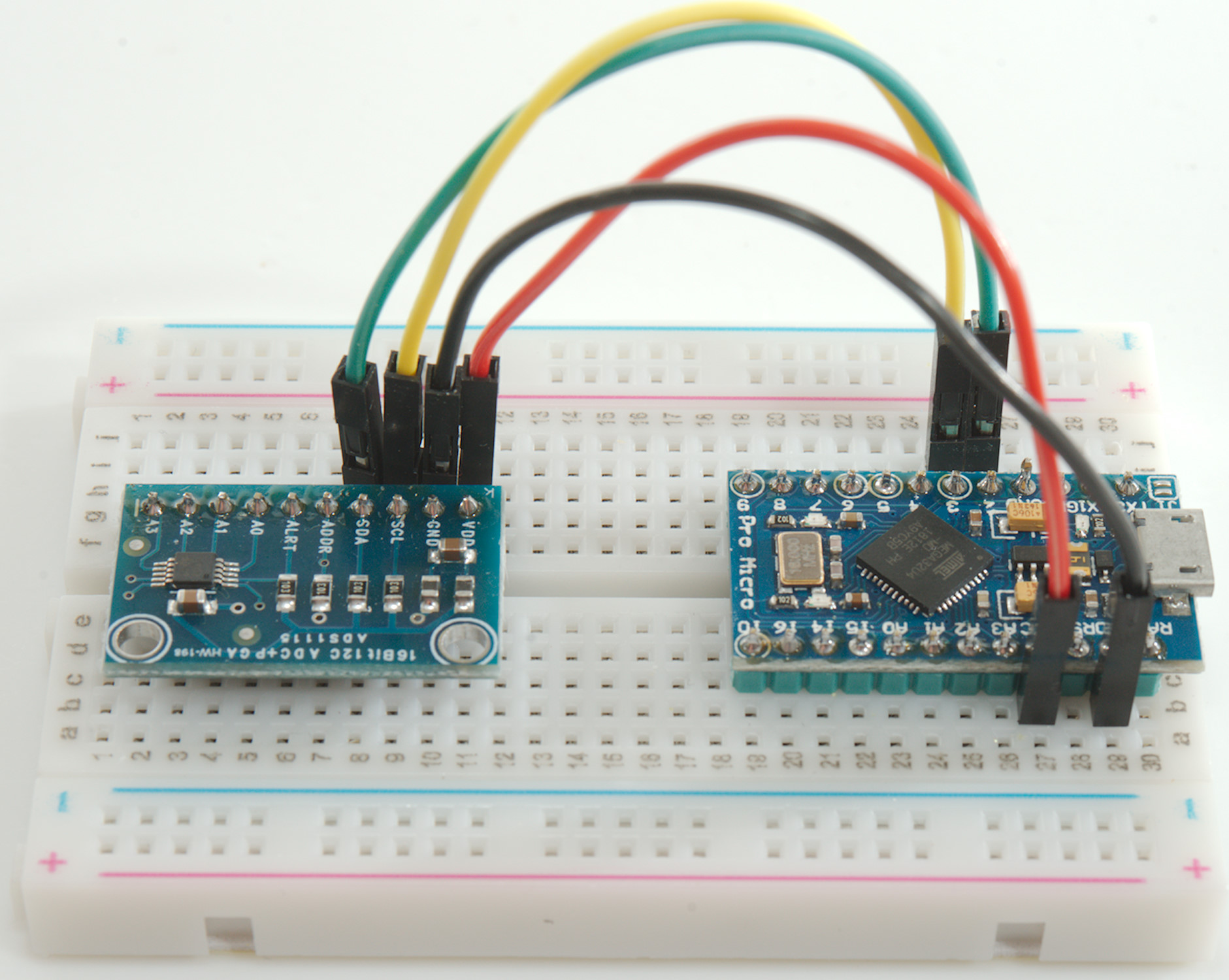
Here is the connections for two of my favorite small Arduinos. The board has build in pull up and pull down, this means no external resistors and ADDR can be be left unconnected.
In both cases the input to A0..A3 must be between GND and VCC, this means sensors will probably need connection to both GND and VCC, maybe with a resistor.
When using the Wire library the pins on the Arduino if fixed, but they can be connected to multiple devices at the same time.
Arduino Nano
Arduino ProMicro

Conclusion
This class has made it very easy for me to use the ADS1115 with low processor overhead, high precision and calibration of output values. Depending on the project I have been using different parts of the library.
Notes and software download
Download library