Demo 16 bit PWM on Arduino
Standard Arduino has PWM functions, but they are only 8 bit, this is not always enough, especially when adjusting brightness of some light. The processors used in the classic Arduinos support 16 bit PWM, but only on a few pins. This code here is an example on how to use it.
What do the different processor support
Some of the classic Arduino processors are ATmega328 (UNO & Nano) and ATmega32U4 (Leonardo & ProMicro). The processors are used in more Arduino boards, but these are the ones I usually uses.
A PWM channel typically uses a timer with one or more hardware PWM registers, for slow PWM it can also be done in software. The 16 bit support are:
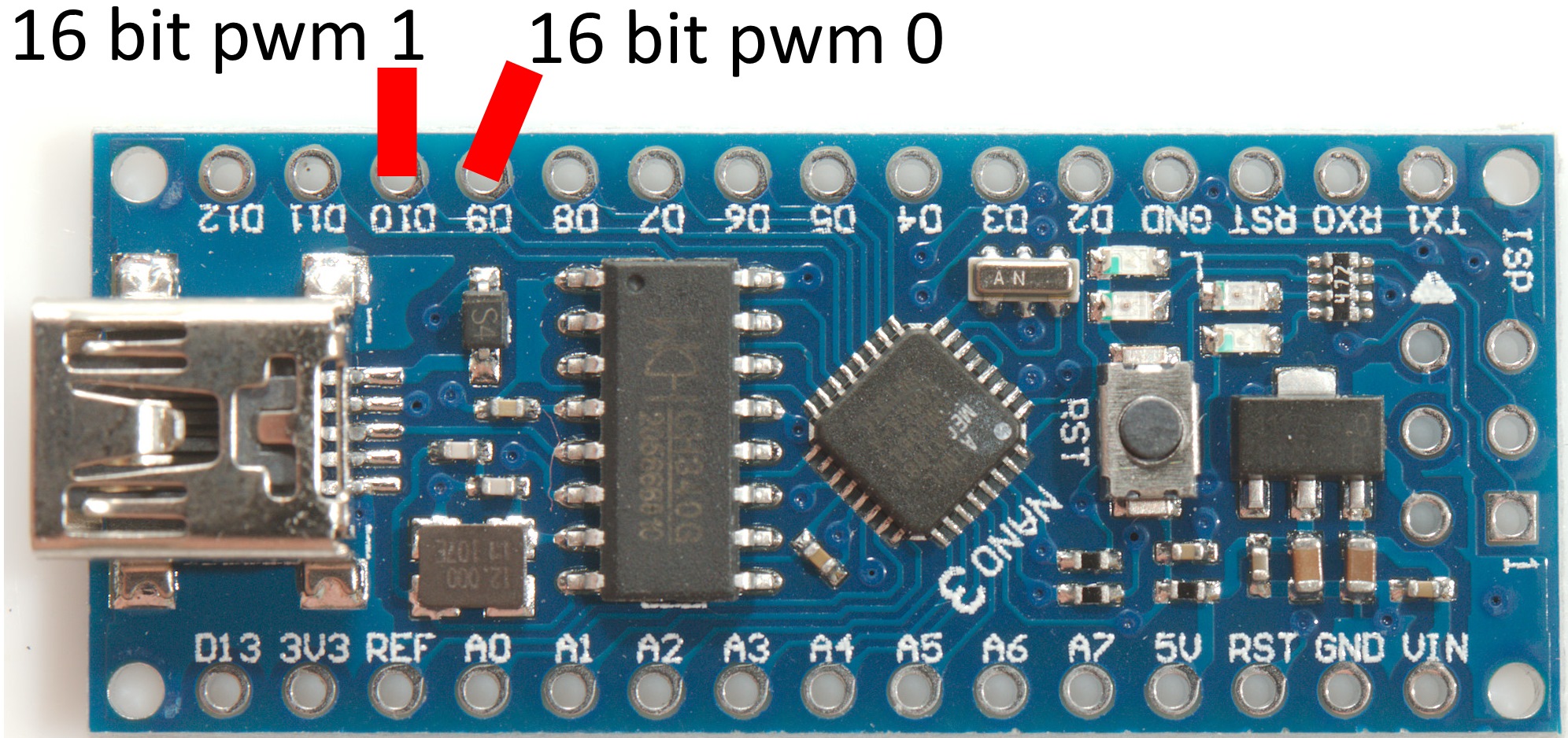
- ATmega328: 2 channels from timer 1 that has two PWM registers.
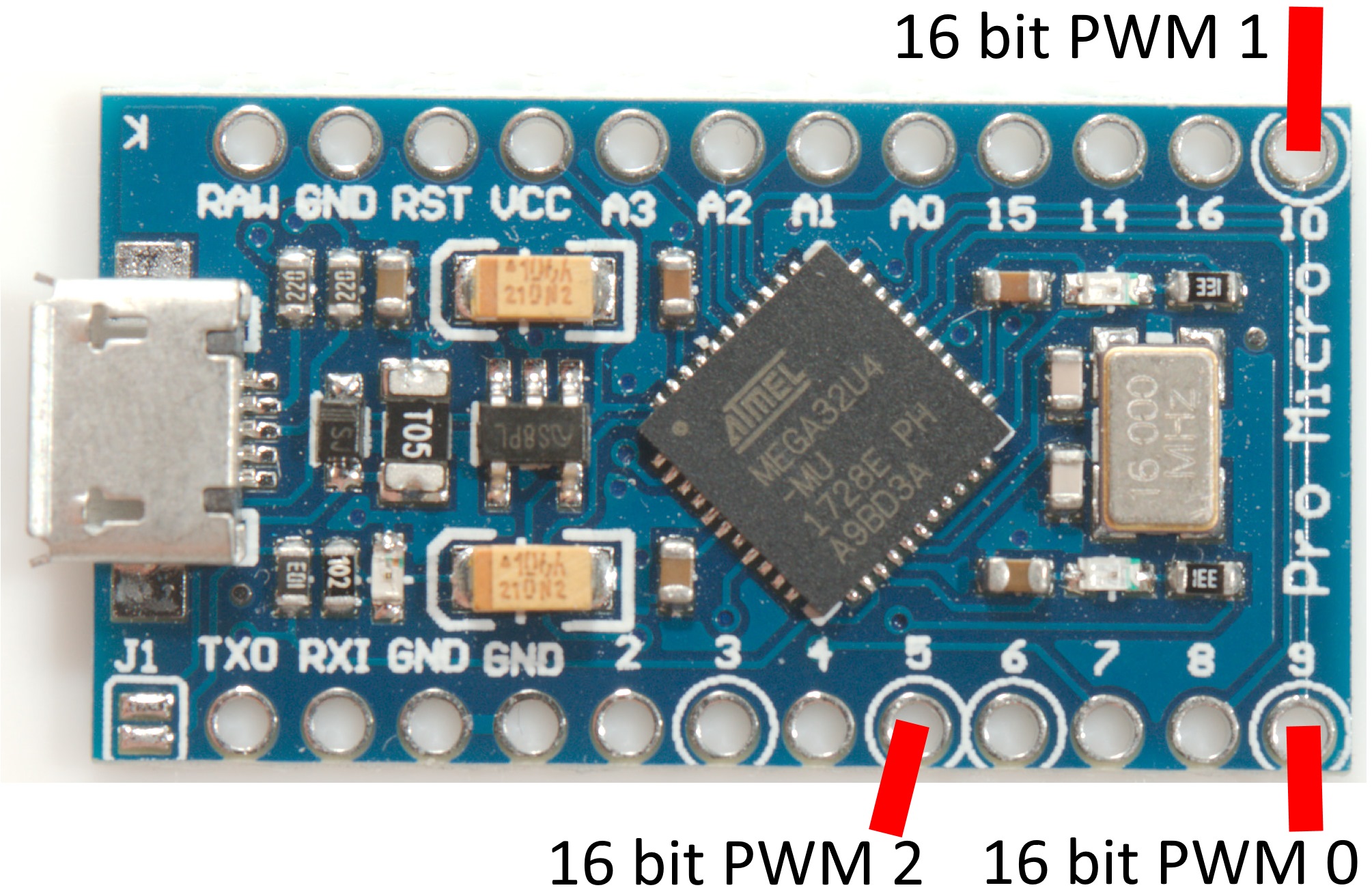
- ATmega32U4: 3 channels from timer 1 & 3 that has two and one available PWM registers (There are more, but the pins are not available).
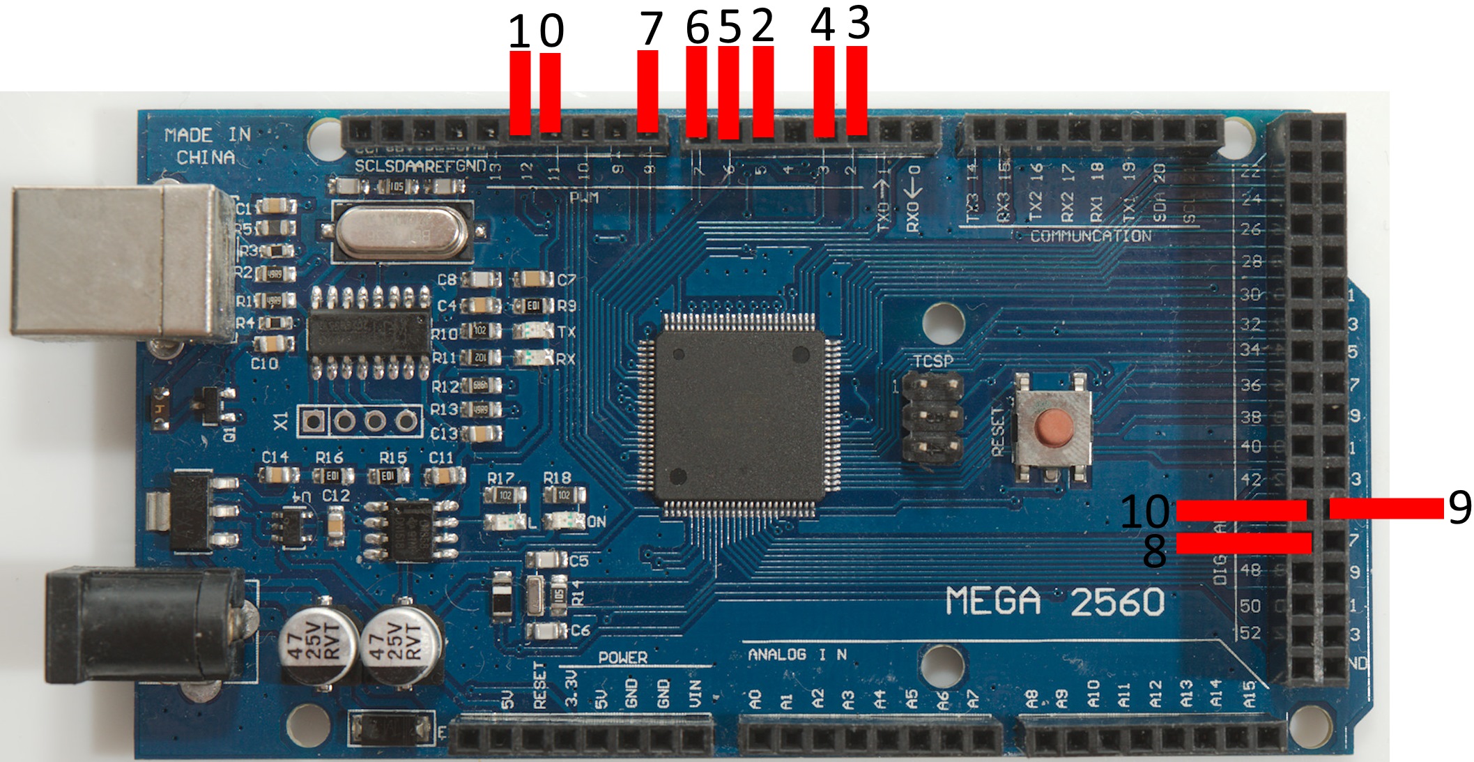
- ATmega2560: 11 channels from timer 1, 3, 4 & 5. 1 has two, the other 3 available PWM registers.
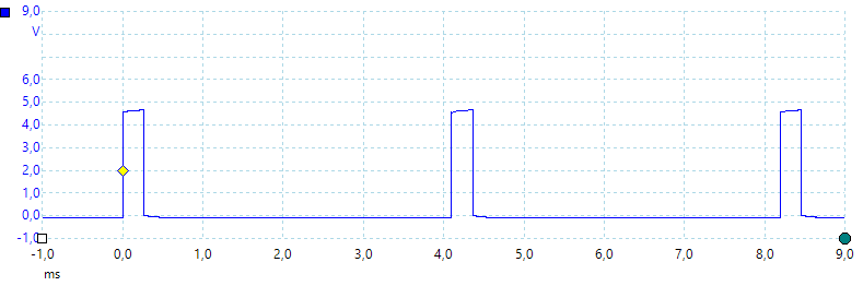
The maximum frequency that can be input to the timers are the Arduino clock frequency, i.e. 16MHz on most processors, with a 65535 step PWM it means the PWM frequency will be 16000000/65535 or 244.14Hz, this is fast enough for brightness regulation.
Code
The code is fairly simple and I have not made a library.
Code:
// This software is written by HKJ from lygte-info.dk
// It is a skeleton for handling 16 bit pwm and depending on processor there will be 2
// Analog A0 is used as a test input.
// This is for UNO and Nano processor
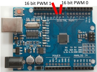
const byte pwm0pin = 9; // PB1, OC1A
const byte pwm1pin = 10; // PB2, OC1B
// This is the maximum PWM value and means the PWM frequency is around 244Hz.
// Reducing this value will increase the PWM frequency and reduce the number of steps
const uint16_t MAX_PWM_VALUE = 65535U;
//----------------------------------------------------------------------------------------------------
// Setup timers for 16 bit PWM
void initPWM() {
noInterrupts();
TCCR1A = 1 << WGM11 | 1 << COM1A1 | 1 << COM1B1; // set on top, clear OC on compare match
TCCR1B = 1 << CS10 | 1 << WGM12 | 1 << WGM13; // clk/1, mode 14 fast PWM
ICR1 = MAX_PWM_VALUE;
interrupts();
pinMode(pwm0pin, OUTPUT);
pinMode(pwm1pin, OUTPUT);
}
//----------------------------------------------------------------------------------------------------
// Set a 16 bit PWM value for a channel
void setPWM(byte no, uint16_t pwm) {
noInterrupts();
switch (no) {
case 0 :
OCR1A = pwm;
break;
case 1 :
OCR1B = pwm;
break;
}
interrupts();
}
//----------------------------------------------------------------------------------------------------
void setup() {
Serial.begin(9600);
while (!Serial);
Serial.println("Starting...");
initPWM();
}
//----------------------------------------------------------------------------------------------------
// Use A0 as test input
void loop() {
setPWM(0,map(analogRead(A0),0,1023,0,MAX_PWM_VALUE));
delay(50);
}
This code is tested on Nano/Uno. It can be copied into a empty sketch or the full sketch can be downloaded (see below).
I use analog A0 input for testing, i.e. connect a potmeter to it for adjusting the PWM.
Better brightness adjustment
The eye do not see brightness linear, this means the first part of the scale change visual brightness significantly, but the last part do not adjust much. This can be improved by using a logarithmic scale.
Here is some code to do that:
Code:
//----------------------------------------------------------------------------------------------------
// All these functions use a logarithmic scale, this means they are ideal for brightness adjustments:
// I have defined 3 ranges 0..100, 0..255 and 0..1023, use the findMaxForPow() function to make others
void setPWM100(byte no, double value) {
  setPWM(no, pow(value, 2.4082365036));
};

void setPWM255(byte no, double value) {
  setPWM(no, pow(value, 2.0014095306));
};

void setPWM1023(byte no, double value) {
  setPWM(no, pow(value, 1.6002234458));
};
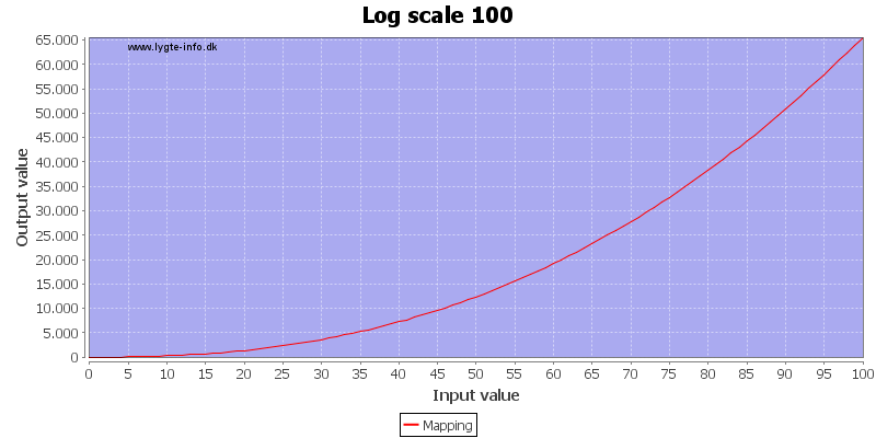
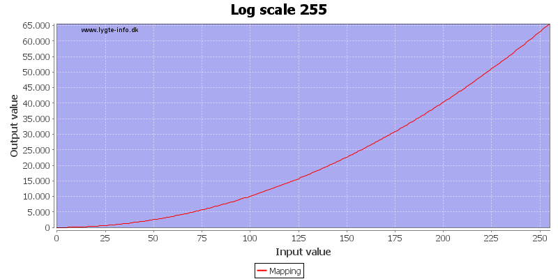
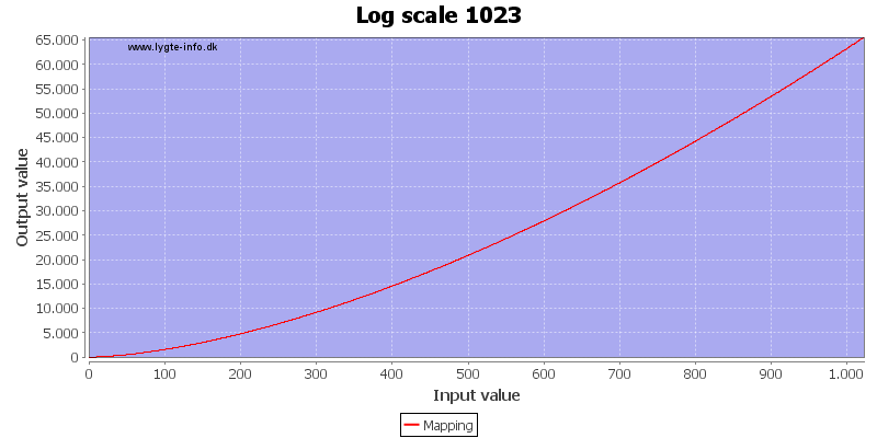
Above is the mapping they uses. At 50% input value the PWM output is only about 15-20%
This also means that noise on the ADC input is less visible in the brightness.
Code:
setPWM1023(1, analogRead(A0));
The 1023 version can be directly used with analogRead(). The 0..100 scale is the best for low levels and it can also be used directly with analog read: setPWM100(10, analogRead(A0)/10.23);
Code:
//----------------------------------------------------------------------------------------------------
void findMaxForPow(uint16_t maxInputValue) {
  double exp = 1;
  double expLast = 0;
  double expadj = 1;
  double v = 0;

  while (exp != expLast) {
    expLast = exp;
    v = pow(maxInputValue, exp);
    if (v > MAX_PWM_VALUE) {
      exp -= expadj;
      expadj = expadj / 10;
    }
    exp += expadj;
  }
  Serial.print(F("For a maximum input value of: "));
  Serial.print(maxInputValue);
  Serial.print(F("  Use: "));
  Serial.print(exp, 10);
  Serial.println(F("  In pow(..) function "));
}
To generate a factor for other maximum scales use the above routine, it will generate a new constant for use in the pow() function.
PWM pins
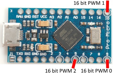
I did not use pin mapping, but instead called the channels 0, 1, 2 ... 10, they map to these pins:
To get support for anything but UNO/Nano the code that can be downloaded below must be used.
UNO
Nano

ProMicro
Mega

Conclusion
As long as only a few high resolutions PWM channels is required the Arduino can do it on its own with very good resolution.
For more channels something like PCA9685 has 16 channels with 12 bit each.
Notes and download
Sketch with all the above code
This code has support ATmega32U4 and ATmega2560a PWM with more channels, this means the code contains #if preprocessor directives to automatic adjust to actual processor.