Display driver library for 7, 14 & 16 segment LED and LCD displays on Arduino
For some of my projects I needed a LED display on the Arduino. This is fairly easy with the library manager in Arduino I could find two libraries supporting the display I wanted (TM1637), but everything was not fine!
In the end I wrote my own driver, it supports many different 7 segments displays and has a broad selection of functions to display data, later on I have added support for 14 & 16 segment displays, this is completely transparent, the same code will run with both types by just changing a #define.
It is not a real library, but best copied into the project directory, due to the "#define". The library uses about 1200 bytes flash for the basic number display on a TM1637 (About 800 bytes on HC595 static).
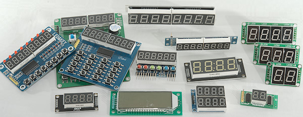
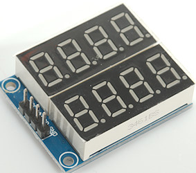
This library supports all the display on the above picture including keys and indicators, and also many other displays.
Contents
Display driver library for 7, 14 & 16 segment LED and LCD displays on Arduino
Requirement
Supported displays
7 vs. 14 vs. 16 segment
HC164 2x4 digit
HC595 2 digit
HC595 4 digit
HC595 4 digit 0.8"
HC595 8 digit
HC595 Static single any number of digit
HC595 Static any number of digit
HC595 large Static any number of digit
HT1621 6 digit LCD display
HT1621 12 digit LCD display
HT16K33 4 digit LED display with indicators (DIY)
HT16K33 6 digit LED display with indicators (DIY)
HT16K33 4 digit LED display with colon and point
HT16K33 4 digit large LED display with colon and a few indicator dots
HT16K33 8 digit LED display
HT16K33 4 digit 14-segment LED display
HT16K33 4 digit 14-segment LED display, SparkFun QWIIC SPX-16xxx
HT16K33 4 digit 16-segment LED display (DIY)
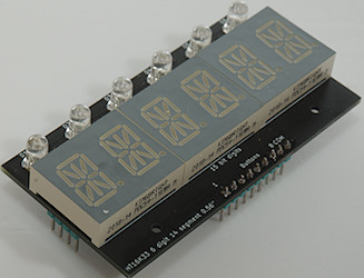
HT16K33 6 digit 14-segment LED display 8 bit digits (DIY)
HT16K33 6 digit 14-segment LED display 15 bit digits (DIY)
HT16K33 8 digit 14-segment LED display
MAX7219 8 or more digit
MAX7219 8 or more digit with 0.56" digits
TM1637 4 digit
TM1637 6 digit RobotDyn
TM1637 6 digit, 6+ keys
TM1638 4 digit
TM1638 8 digit, 8 indicators, 8 keys
TM1638 8 digit, 16 indicators, 8 keys
TM1638 8 digit, 16 keys
TM1638 8 digit, 2 indicators, 24 keys
The software
The simple usage
Show a number
Using it for a clock display
Controlling segments directly
A temperature display
Displaying text
Optimizing library for the applications: #define
Display type select
DELAY_TIME
_FAST_CLOCK_
_ENABLE_6_DIGITS_
_INCLUDE_BYTE_
_INCLUDE_SCROLLING_TEXT_
MAX_DIGITS
Constants
MAX_BRIGHTNESS
DIGIT_TYPE
SEGMENTS_7
SEGMENTS_14
SEGMENTS_16
_USE_INDICATOR_ and INDICATOR_TYPE
_KEYS_ and KEY_TYPE
DISPLAY_INTR
Other
Character constants for 7 segments displays
Symbols and numbers (0x20..0x3f)
Upper case letters (0x40..0x5f)
Lower case letters (0x60..0x7f)
Other symbols
Character constants for 14 segments displays
Symbols and numbers (0x20..0x3f) 14 segments
Upper case letters (0x40..0x5f) 14 segments
Lower case letters (0x60..0x7f) 14 segments
Other symbols 14 segments
Character constants for 16 segments displays
Symbols and numbers (0x20..0x3f) 16 segments
Upper case letters (0x40..0x5f) 16 segments
Lower case letters (0x60..0x7f) 16 segments
Other symbols 16 segments
All functions
General notes
Constructors
Bytes and integers
Bytes and integers in hex (BCD)
Bytes and integers in binary
Float and double (They are the same on a MEGA)
Text, strings and characters
Indicator segments
Direct segment access
Key input
Support routines
Print and LCD API
Constructors
LCD API
How is the software designed
Display selection and optimization (Header file)
Constant definition and feature setup (Header file)
Segments definition (Header file)
IO port handling (Header file)
Class header (Header file)
Class header LCD API (Header file)
Interrupt handler/vector (Header file)
Number and letter tables (cpp file)
The class code (cpp file)
Timer and interrupt initialization (cpp file)
Display drivers (cpp file)
Not working, what to look for
Compatibility between displays
My favorites and dislikes
Favorites
Dislikes
Conclusion
Notes and download
Requirement
I wanted a flexible and easy to use display driver library, my initial list of requirements was:
- Support int.
- Support hex.
- Support raw data.
- Support float, four digits with a point can show from 0.001 to 9999, I need that for some projects.
- Support both 4 and 6 digit versions of the display.
- Support displaying on any digits
- Support the point before the number for float, i.e. use first digit for status and point, giving a range of .001 to 999
- Display update can be either automatic each time a function is called or on request (Useful when multiple call is used to setup the display).
- Include segment definitions for possible letters and a easy way to display them.
- Generally the functions must not require many parameters when not needed.
- Lots of shorthand functions for the most common display requirements.
- Compact, i.e. it must not use much flash and ram memory.
Later one I added a few more requirements:
- Support for other display types, this means anything I could find on ebay for reasonable price.
- Possibility to chain MAX7219.
- More support for float and decimal point.
- Support for displays with indicators.
- Support for displays with keys.
- Support for binary digits display with 2 digits for each digit.
- Support for text display.
This may sound like a large library and it do contain a fair amount of code, but the compiler will strip unused code and with the defines I only include code for the selected display type. This means memory usage will usually be fairly low.
Supported displays
For a overview use this list: 7 & 14 segment display modules specifications
Each display type requires a change in the top of the ".h" file where the relevant #define must be un-commented and all the other must be commented out.
The displays listed below are the ones I have tested with, other displays with the same driver chip will often be supported.
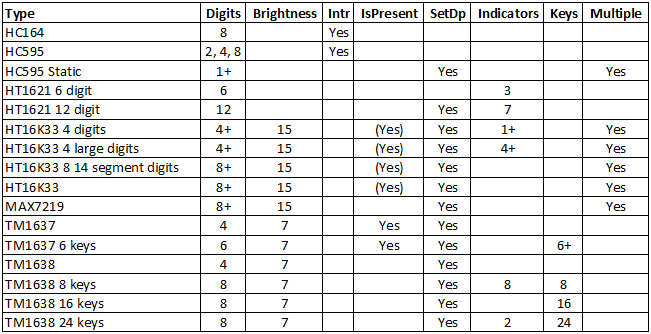
The above table shows what is supported on different displays.
- Digits: Number of digits, this is based on driver chip and what is available
- Brightness: Brightness setting and number of levels.
- Intr: Requires an interrupt handler
- IsPresent: It is possible to detect if display is connected, with multiple display it will show the result for the last display.
- SetDp: A independent point/colon setup.
- Indicators: LED's or other indicators
- Keys: Input from keys
- Multiple: More than one display, they will look like a long display in software.
7 vs. 14 vs. 16 segment
Mostly there is no difference between using 7, 14 & 16 segment displays, all the functions works the same way and will show the same, only the numbers and especially the letters looks different on 14 & 16 segment displays. The 14 & 16 segment display also support a few more symbols. With the 16 segment display some lower case letters looks better, but the decimal point is a program.
When using direct segment access there is a difference, this means showDigits() and getDigits() use slightly different types. As long as showDigit() is used with digit... and SEG_... constants there is no difference for it.
The 14 & 16 segment displays will usually use more memory because it needs 16 bit or even 32 bit instead of 8 bit structures for buffer and character table, but it is a small amount of memory (Up to 150 bytes flash and 10-30 bytes ram on mega processors for 16 bit).
If code must be able to work on both 7, 14 & 16 segments avoid using the SEG_ constants or make separate defines for 7, 14 & 16 segments.
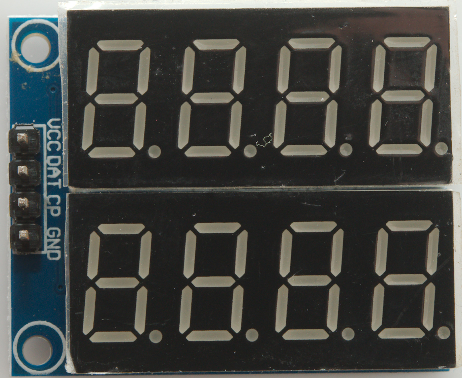
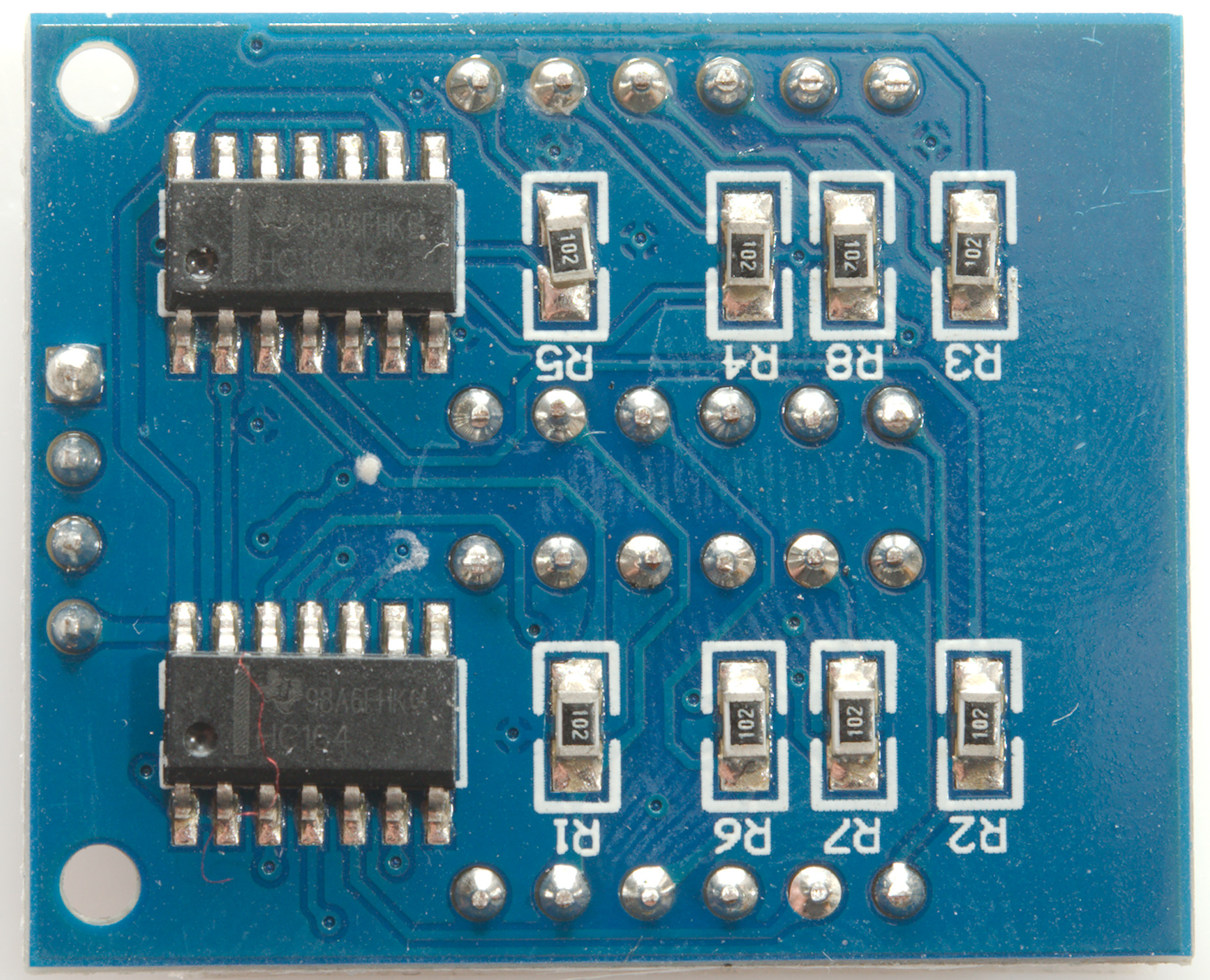
HC164 2x4 digit

Connections: data=DAT, clock=CP
Display type: _HC164_
The HC164 is a fairly bad choice as display driver because the display driver pins are on while data is being shifted in. For this to give a usable display _FAST_CLOCK_ must be enabled and DELAY_TIME must be defined as 0, but some segments will flicker occasionally.
The display uses interrupts.
Ebay search
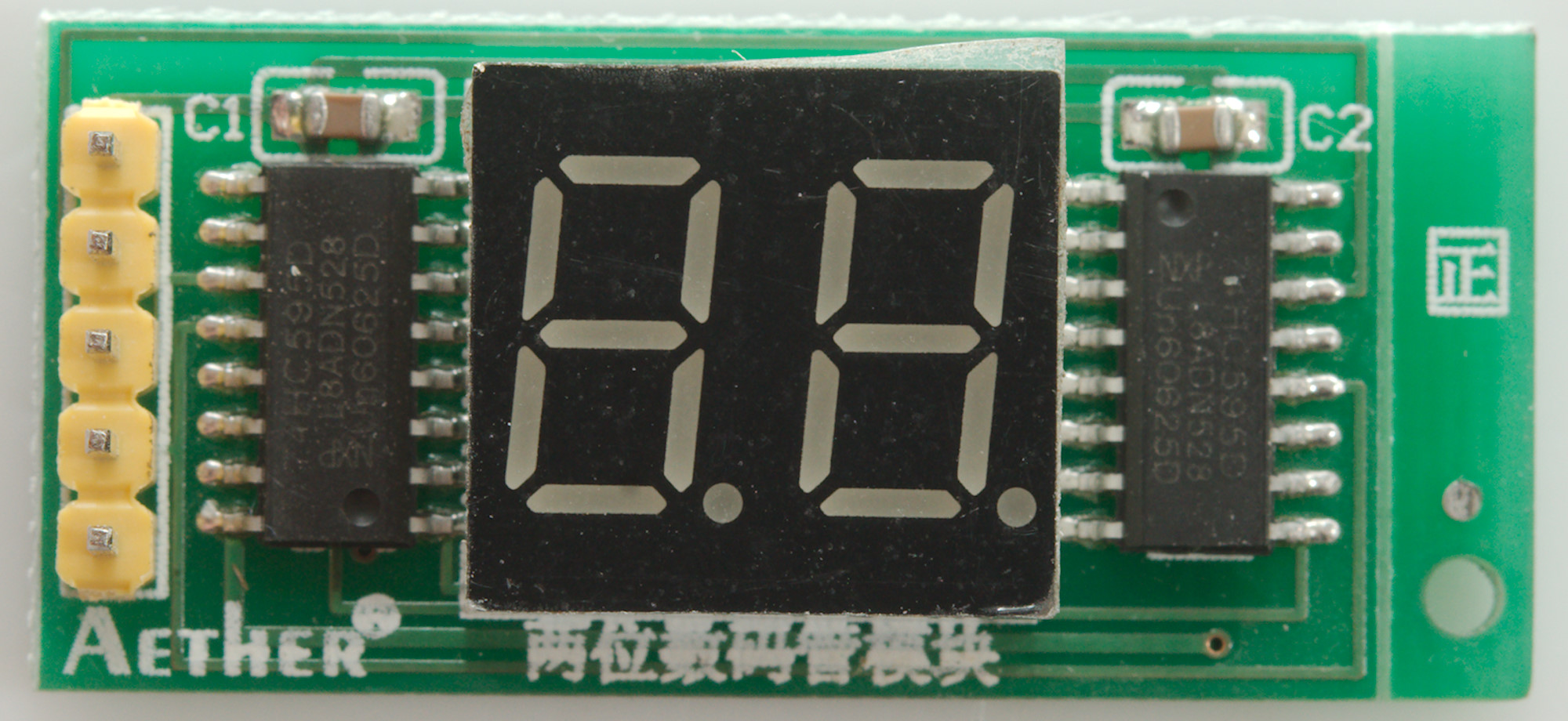
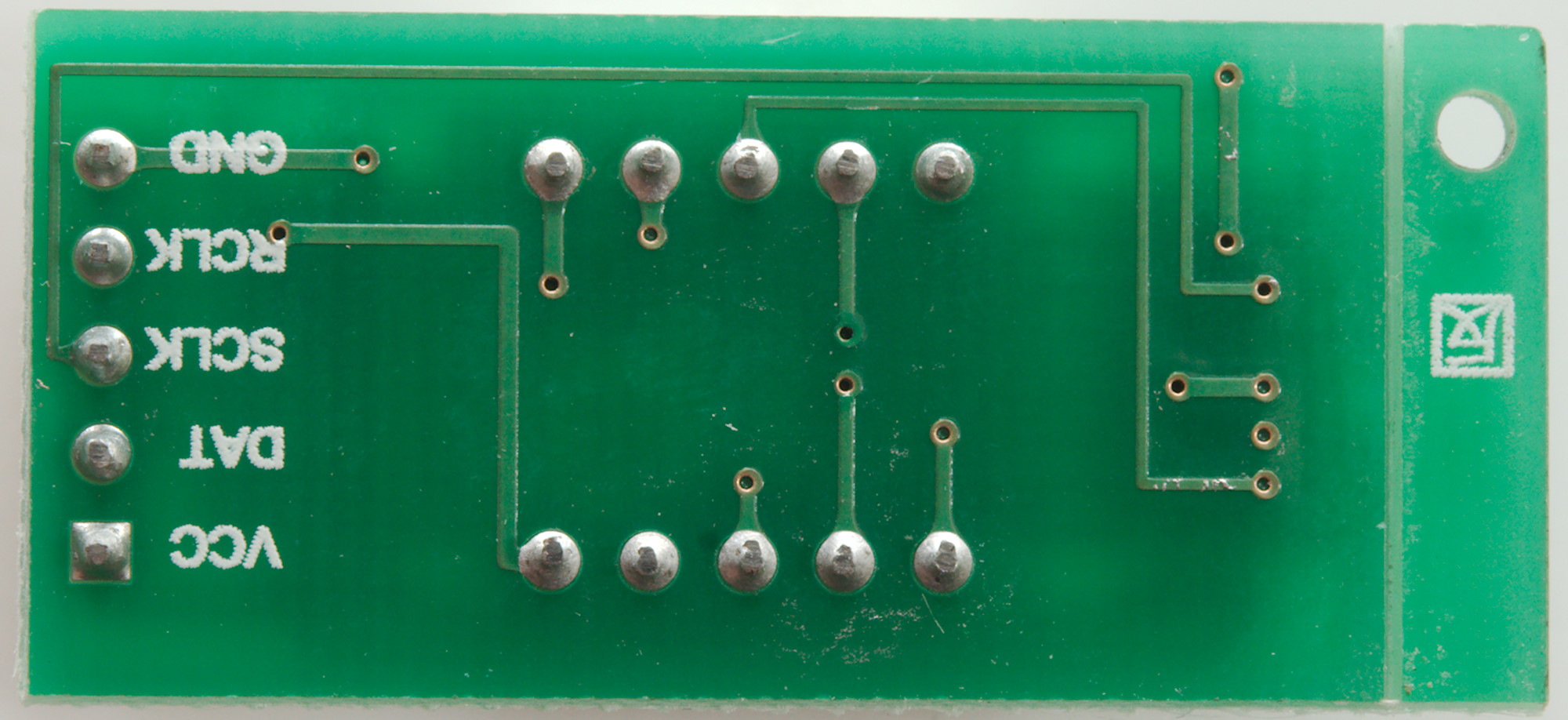
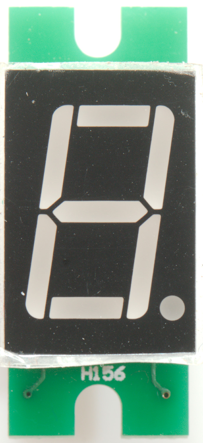
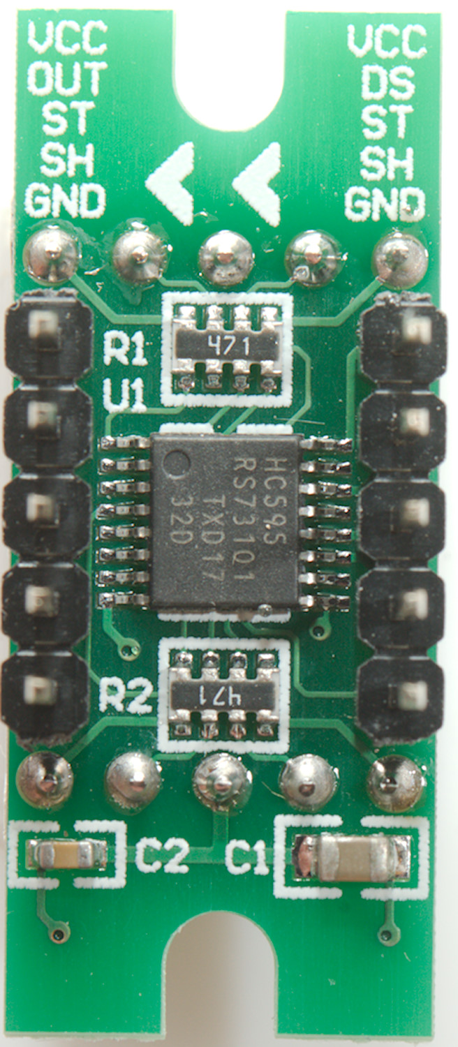
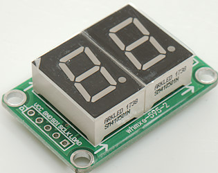
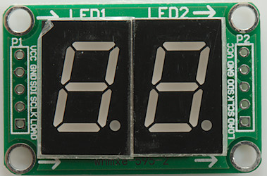
HC595 2 digit

Connections: data=DAT, clock=SCLK, load=RCLK
Display type: _HC595A_
With this display one HC595 contains the segment data, the other select digit, this means it must be update multiple times each second.
It is recommended to use fast mode with this display (_FAST_CLOCK_ defined and DELAY_TIME 0) to reduce the amount of processor time used for updating.
The display uses interrupts.
Ebay search
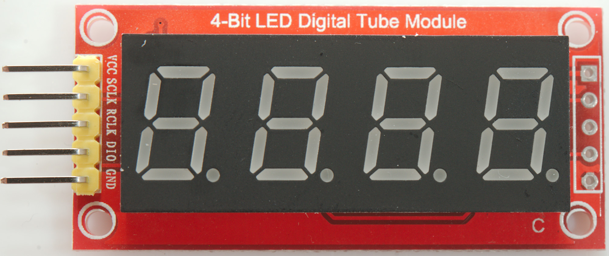
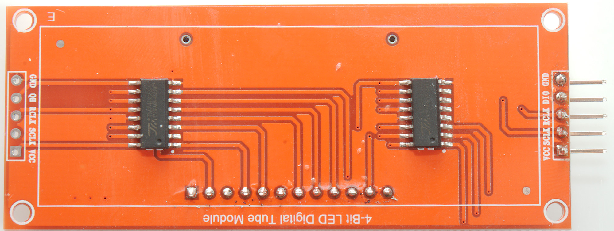
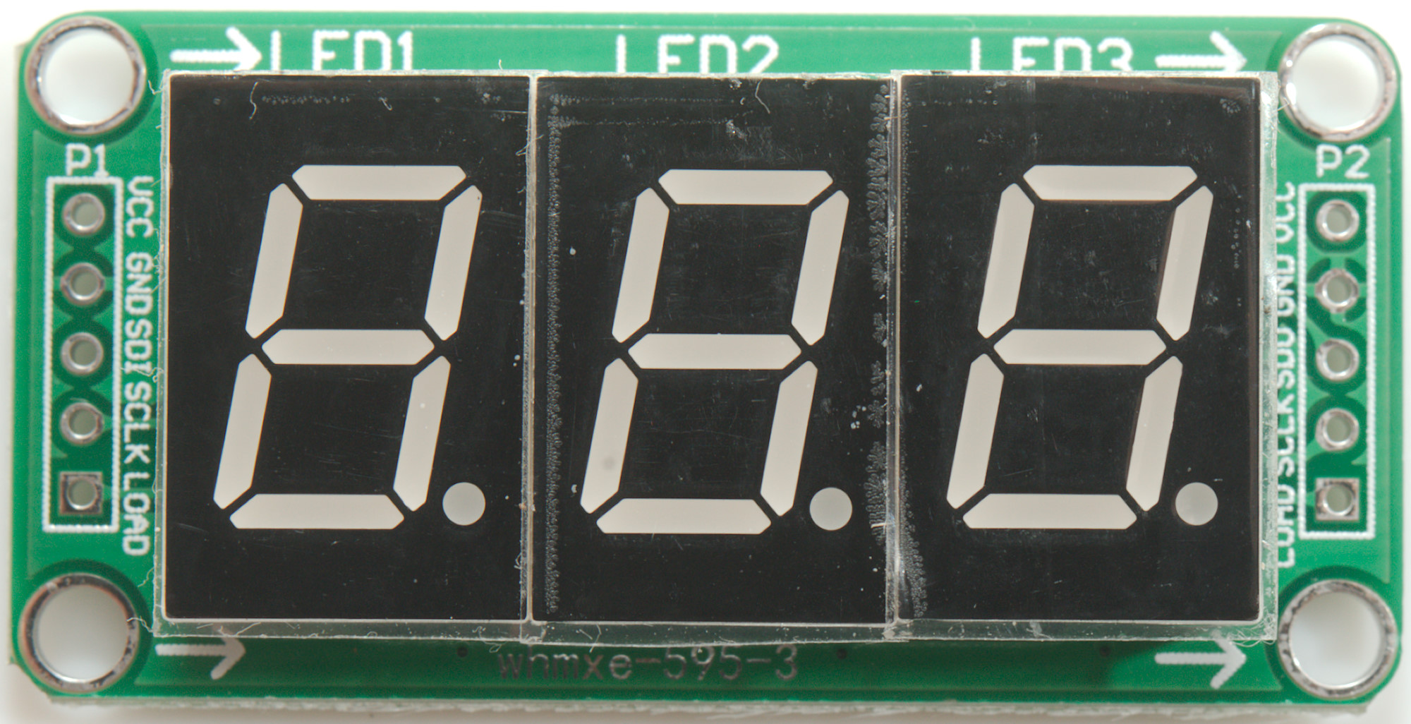
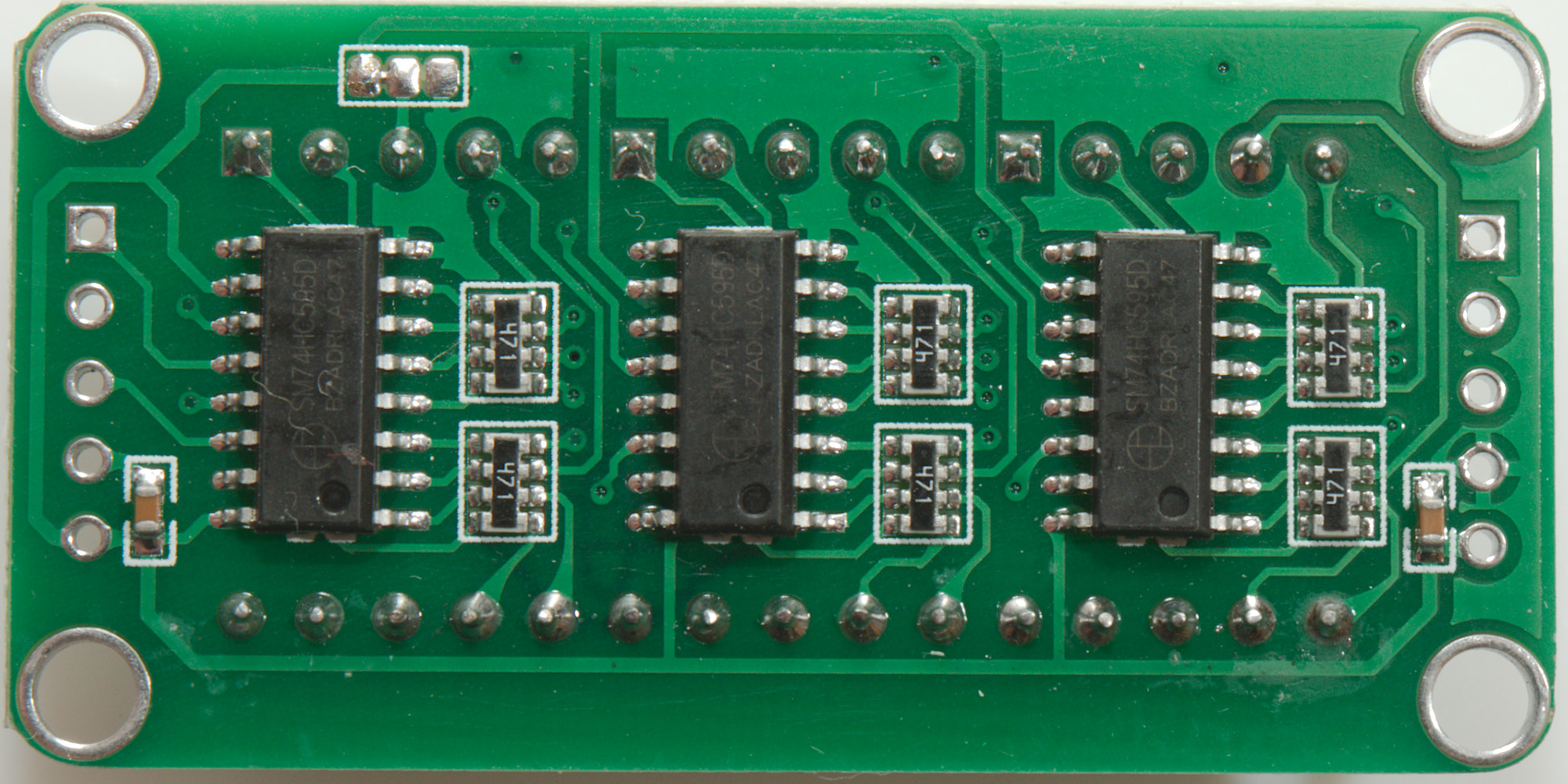
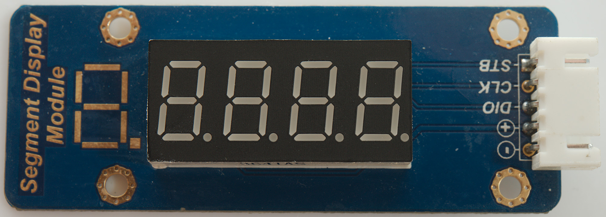
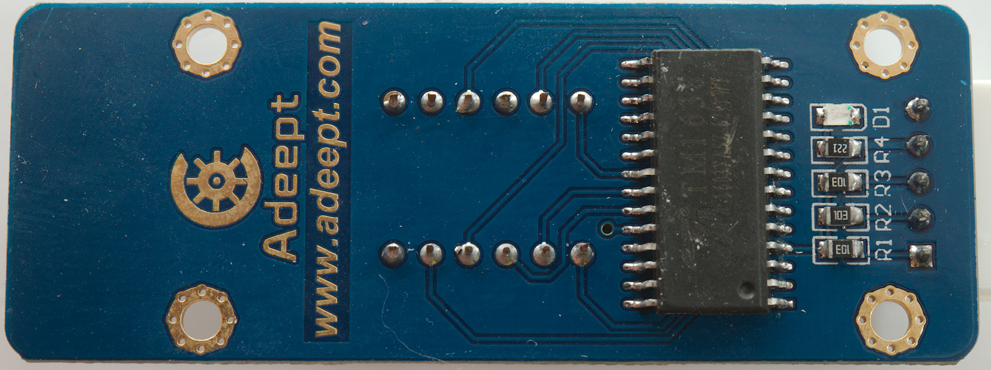
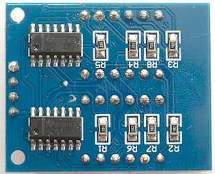
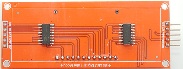
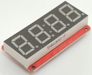
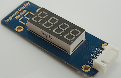
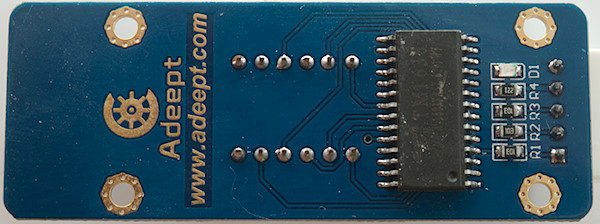
HC595 4 digit
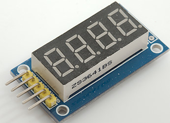
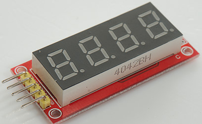
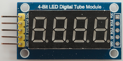
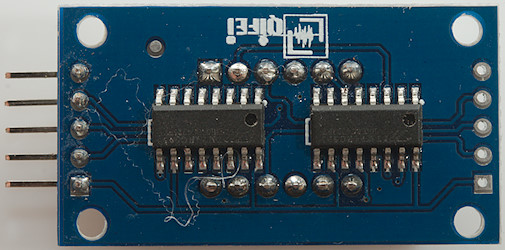
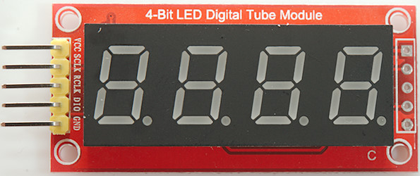
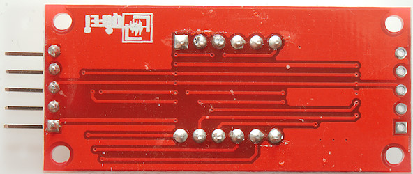
Connections: data=DIO, clock=SCLK, load=RCLK
Display type: _HC595_
With this display one HC595 contains the segment data, the other select digit, this means it must be update multiple times each second.
It is recommended to use fast mode with this display (_FAST_CLOCK_ defined and DELAY_TIME 0) to reduce the amount of processor time used for updating.
The display uses interrupts.
Ebay link
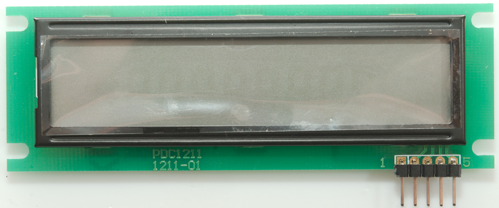
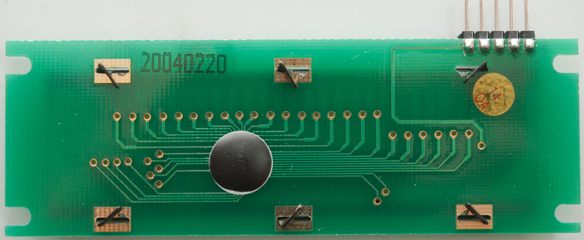
HC595 4 digit 0.8"
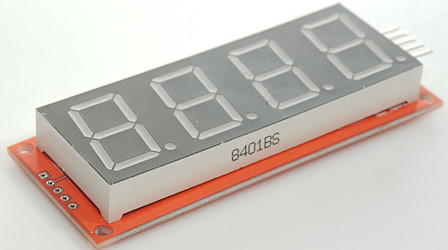
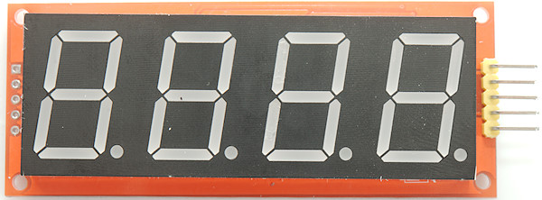
Connections: data=DIO, clock=SCLK, load=RCLK
Display type: _HC595R_
With this display one HC595 contains the segment data, the other select digit, this means it must be update multiple times each second.
It is recommended to use fast mode with this display (_FAST_CLOCK_ defined and DELAY_TIME 0) to reduce the amount of processor time used for updating.
The display uses interrupts.
Ebay link
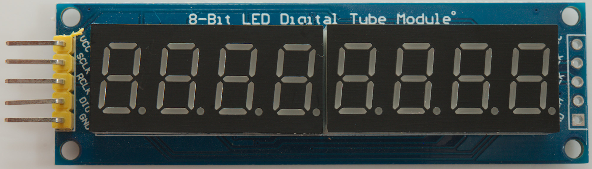
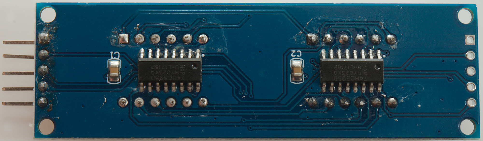
HC595 8 digit
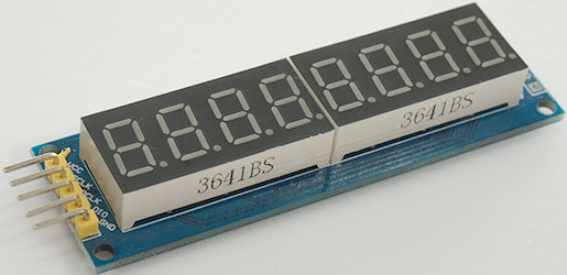
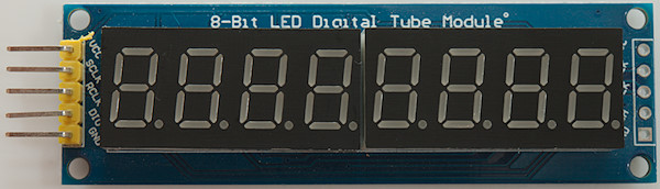
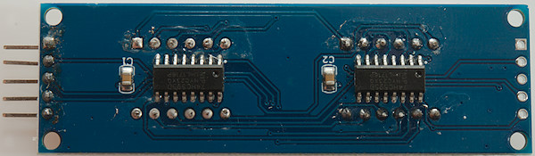
Connections: data=DIO, clock=SCLK, load=RCLK
Display type: _HC595_
With this display one HC595 contains the segment data, the other select digit, this means it must be update multiple times each second.
It is recommended to use fast mode with this display (_FAST_CLOCK_ defined and DELAY_TIME 0) to reduce the amount of processor time used for updating.
The display uses interrupts.
Ebay link
HC595 Static single any number of digit
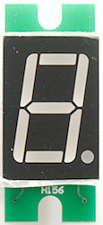
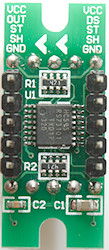
Connections: data=DS, clock=SH, load=ST
Display type: _HC595_STATIC_
This is a simple LED display and with static drive the digits are always stable. This display is made for chaining to an arbitrary size.
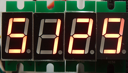
4 digits chained together with jumpers.
Ebay link
HC595 Static any number of digit
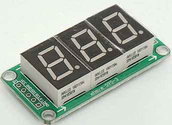
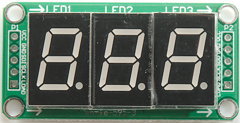
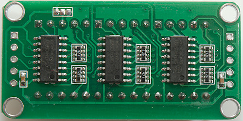
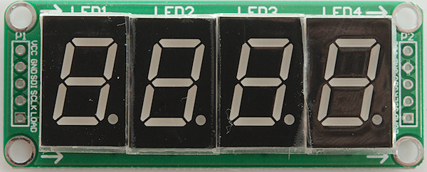
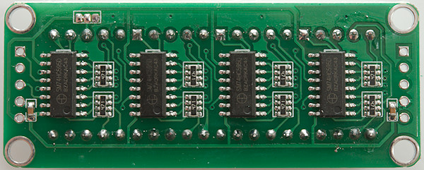
Connections: data=SDI, clock=SCLK, load=LOAD
Display type: _HC595_STATIC_
This is a simple LED display and with static drive the digits are always stable. It is possible to chain displays for any number of digits. When using more than 8 digits remember to increase the buffer (MAX_DIGITS).
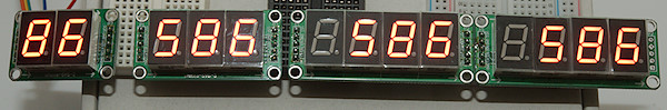
A couple of display is driven from the same output, the frame buffer (MAX_DIGITS) was increased to support the displays.
Ebay search
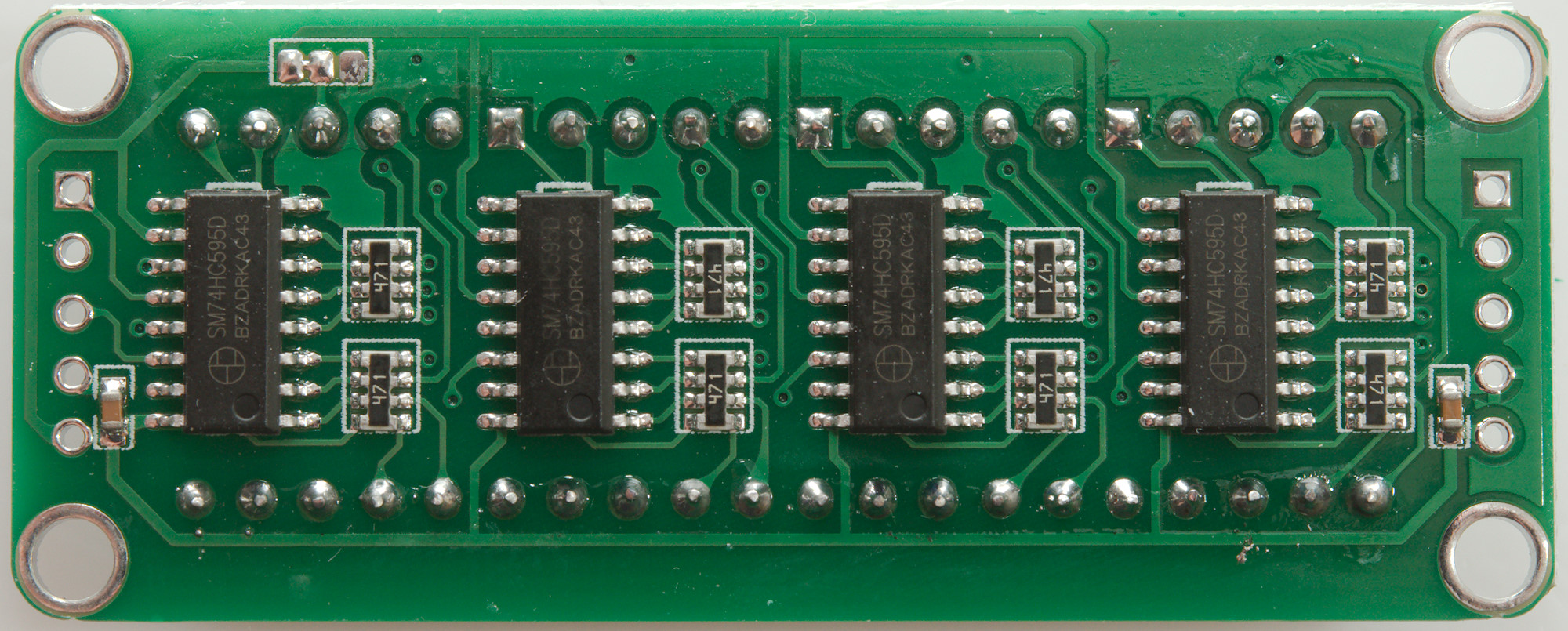
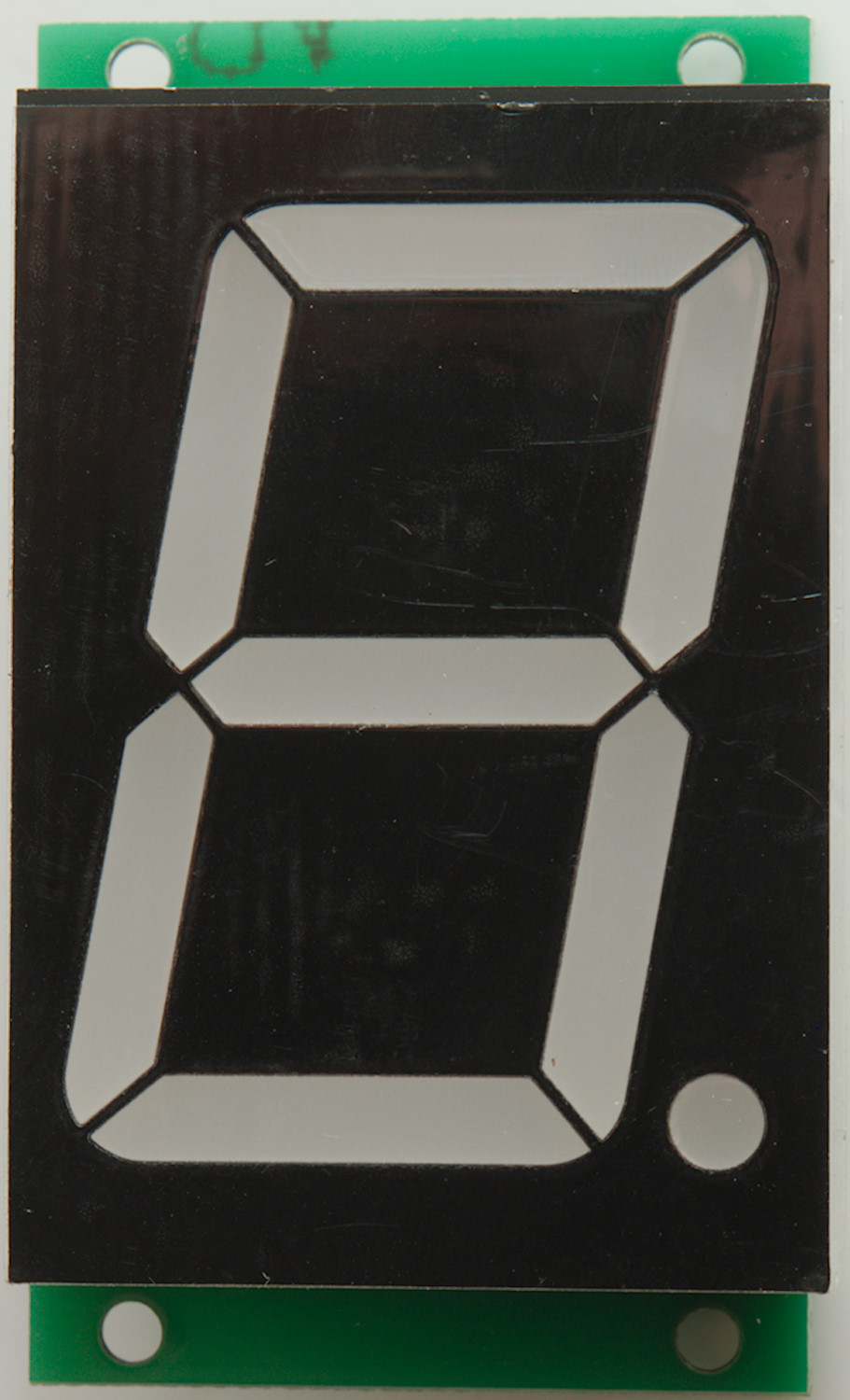
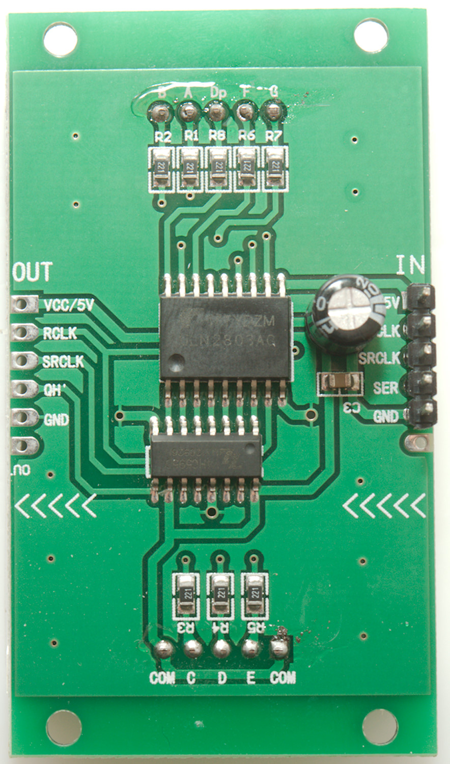
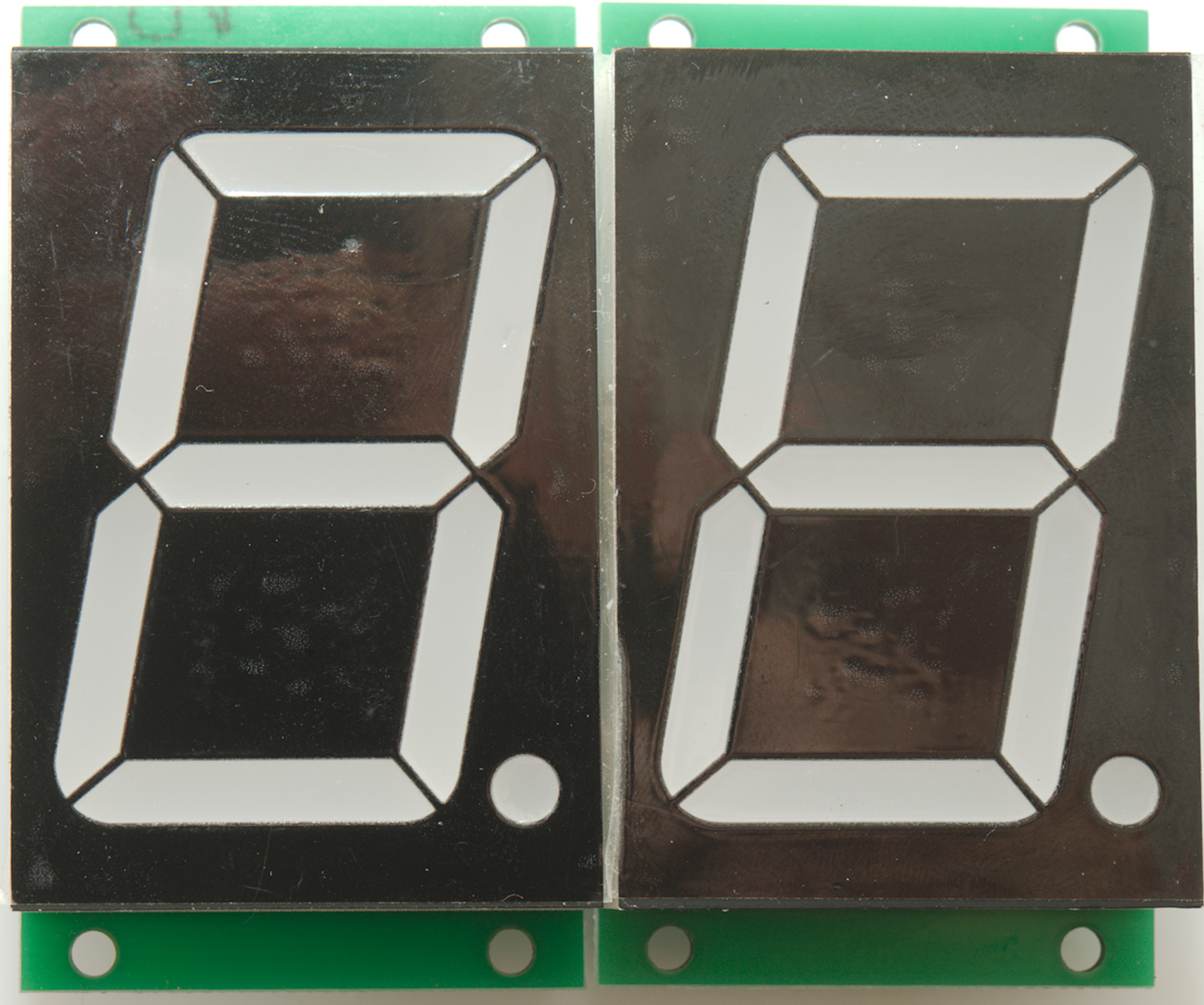
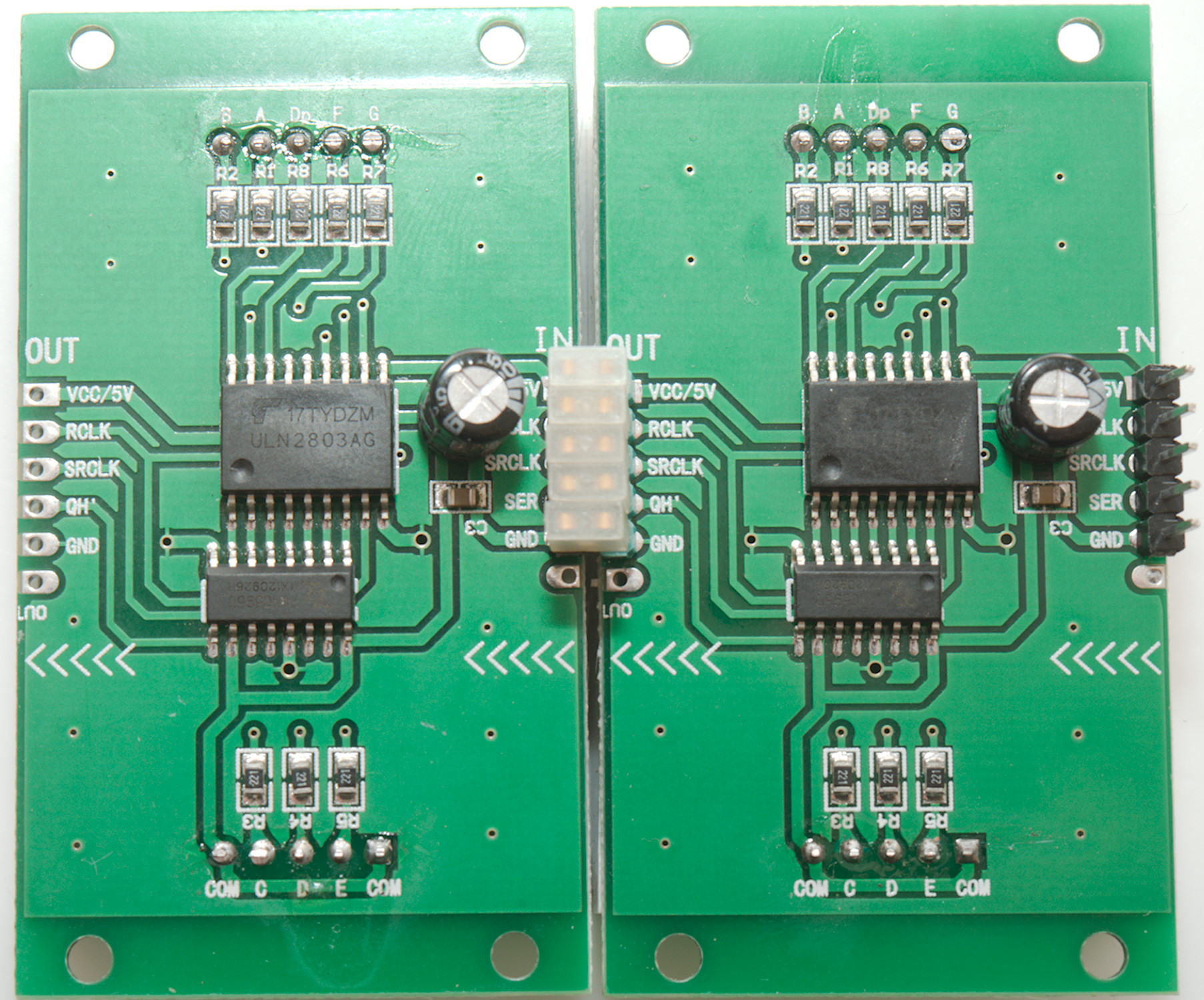
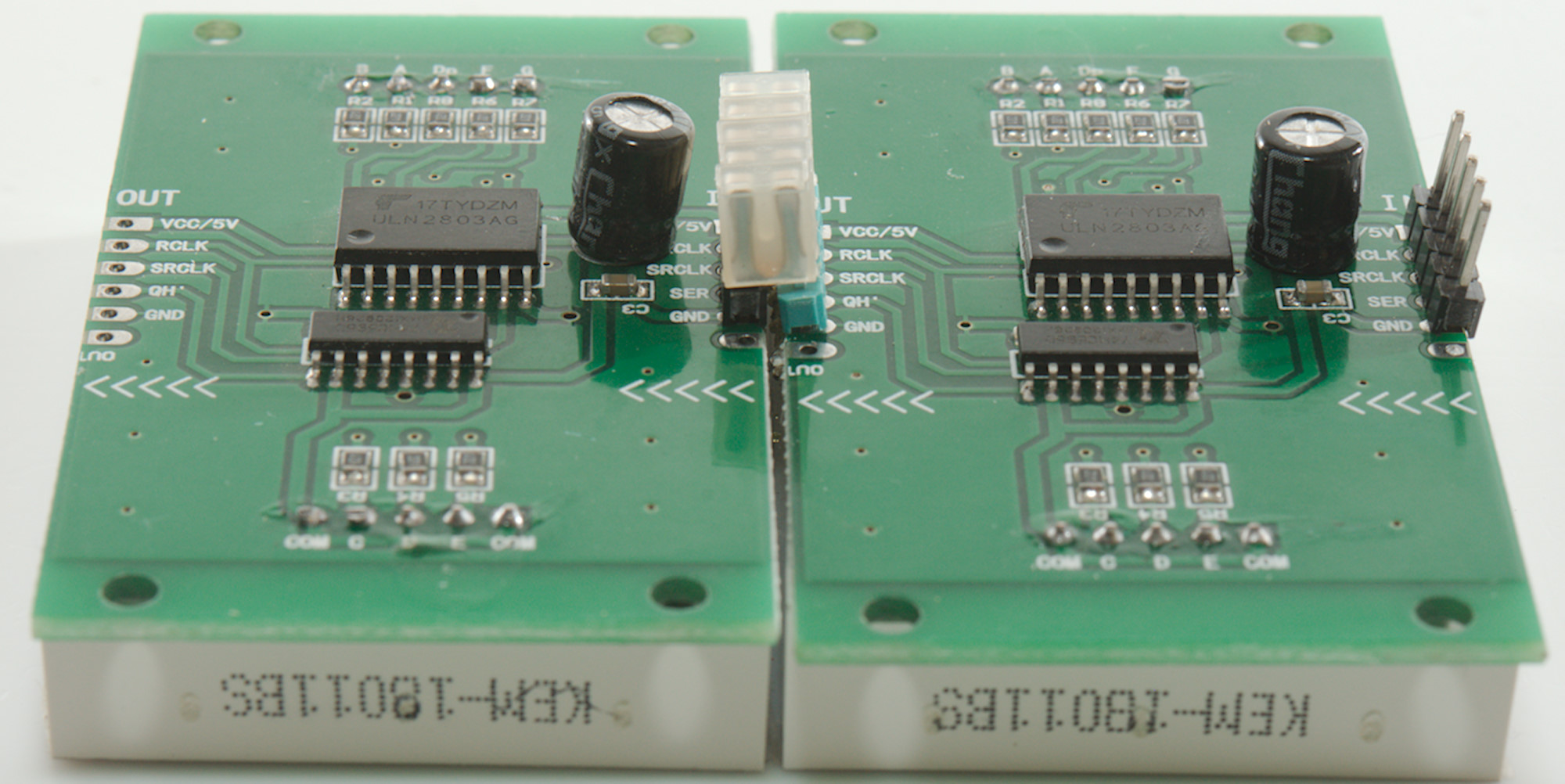
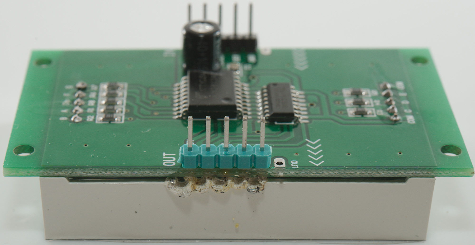
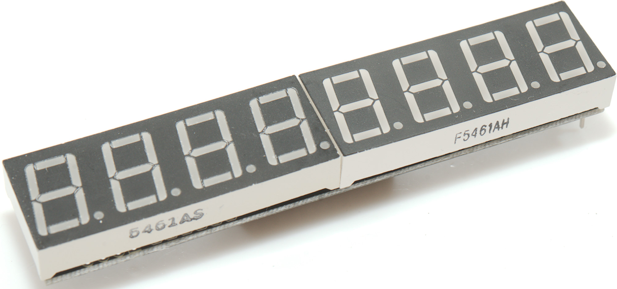
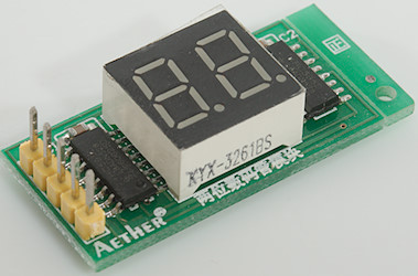
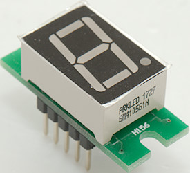
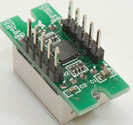
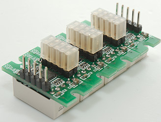
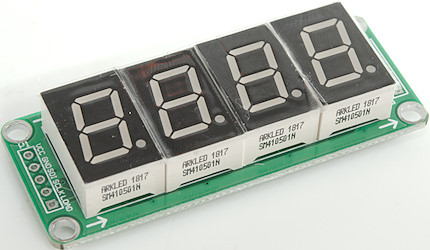
HC595 large Static any number of digit
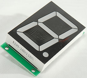
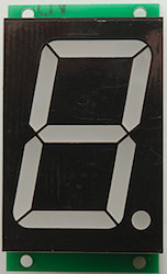
A single digit.


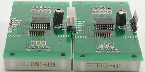
Two digits linked together.
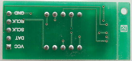
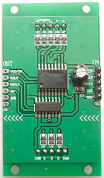
Connections: data=SER, clock=SRCLK, load=RCLK
Display type: _HC595A_STATIC_
This is large digits with a HC595 for static drive and current amplified by a ULN2803. Any number of digits can be linked together, but it may be necessary to use extra GND and VCC connections if many digits are used. When using more than 8 digits remember to increase the buffer (MAX_DIGITS).
The decimal point is much brighter than the other digits because it uses the same 220ohm resistor, for a better looking display it must be replaced with a higher value.

It is a bit difficult to solder a pin header into the output holes, there is no space for the solder iron. Other solutions would be to either solder the pin header in with the plastic up and then push it down or remove the pin header from the other digits (Remove plastic, then use pliers to pull each pin while heating solder) and use wire links instead.
Aliexpress link
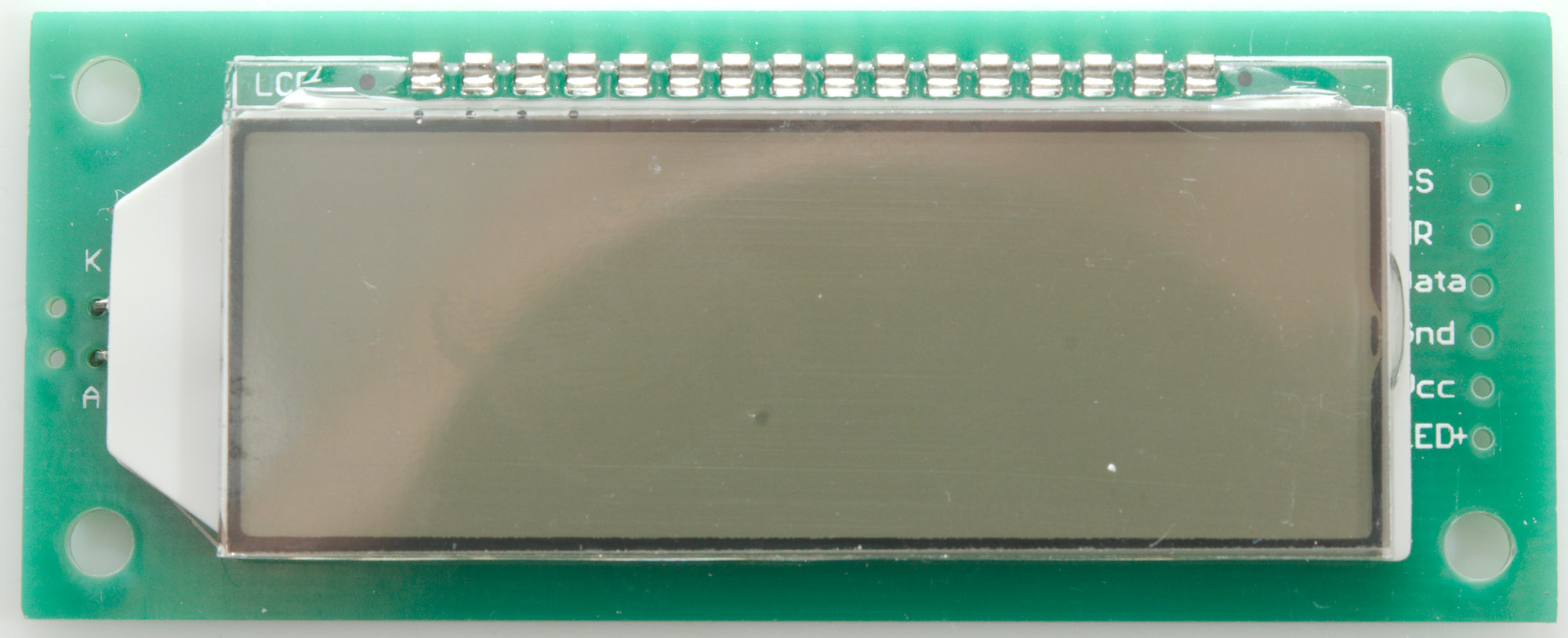
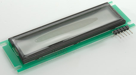
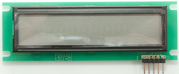
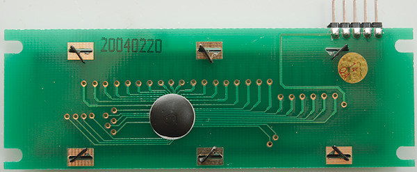
HT1621 6 digit LCD display
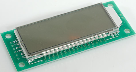
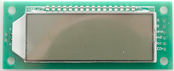
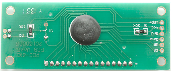
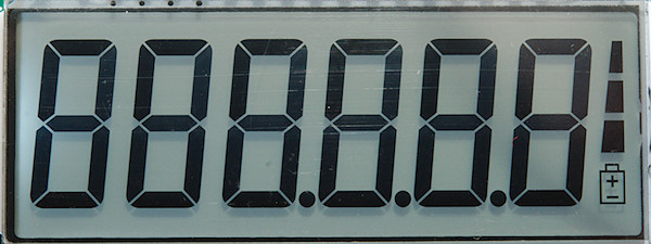
Connections: data=Data, clock=WR, load=CS, depending on S1 (solder bridges) the backlight is powered from Vcc or LED+
Display type: _HT1621_6D_
This is a LCD display with background light, 6 digits and battery indicator, as can be seen the point is only support on some digits. The points has a offset compared to the digit and the missing points are used for the battery indicator, all this is mostly handled by the driver. It will ignore non-existing points, this means float may be missing a point if it is supposed to be in one of the two first positions. For controlling the battery symbol use showIndicators() with BATT_LOW, BATT_MEDIUM and BATT_HIGH, each will turn on one symbol.
This selection only works with this display, not with other HT1621 based displays!
Ebay search
HT1621 12 digit LCD display
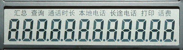
Connections: data=3, clock=2, load=1, GND=4, Vcc=5
Display type: _HT1621_12D_
This is a LCD display with 12 digits and 7 indicators. For controlling the indicators use showIndicators(). This display type will redefine MAX_DIGITS to 12.
This selection only works with this display, not with other HT1621 based displays!
Ebay search
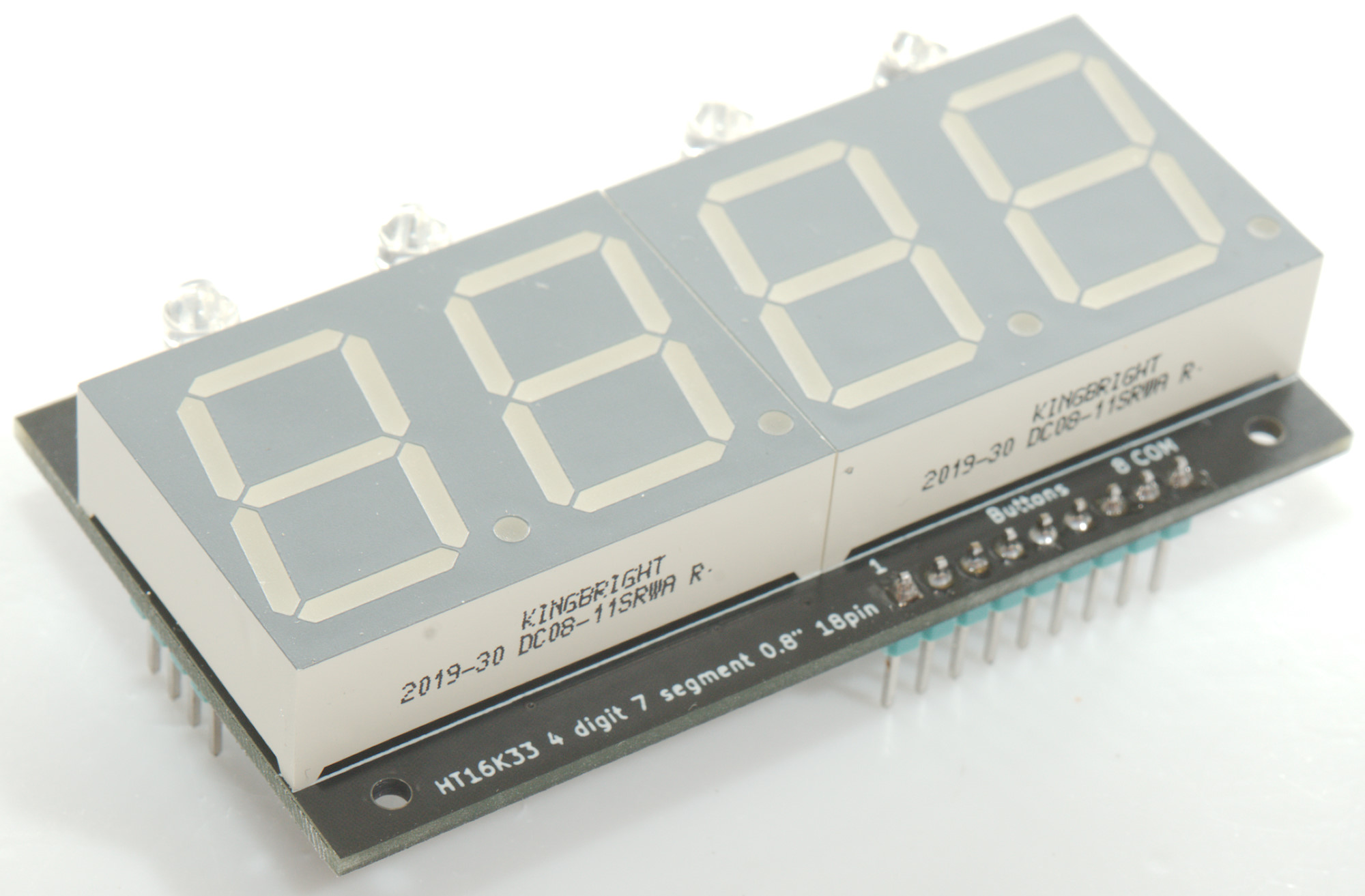
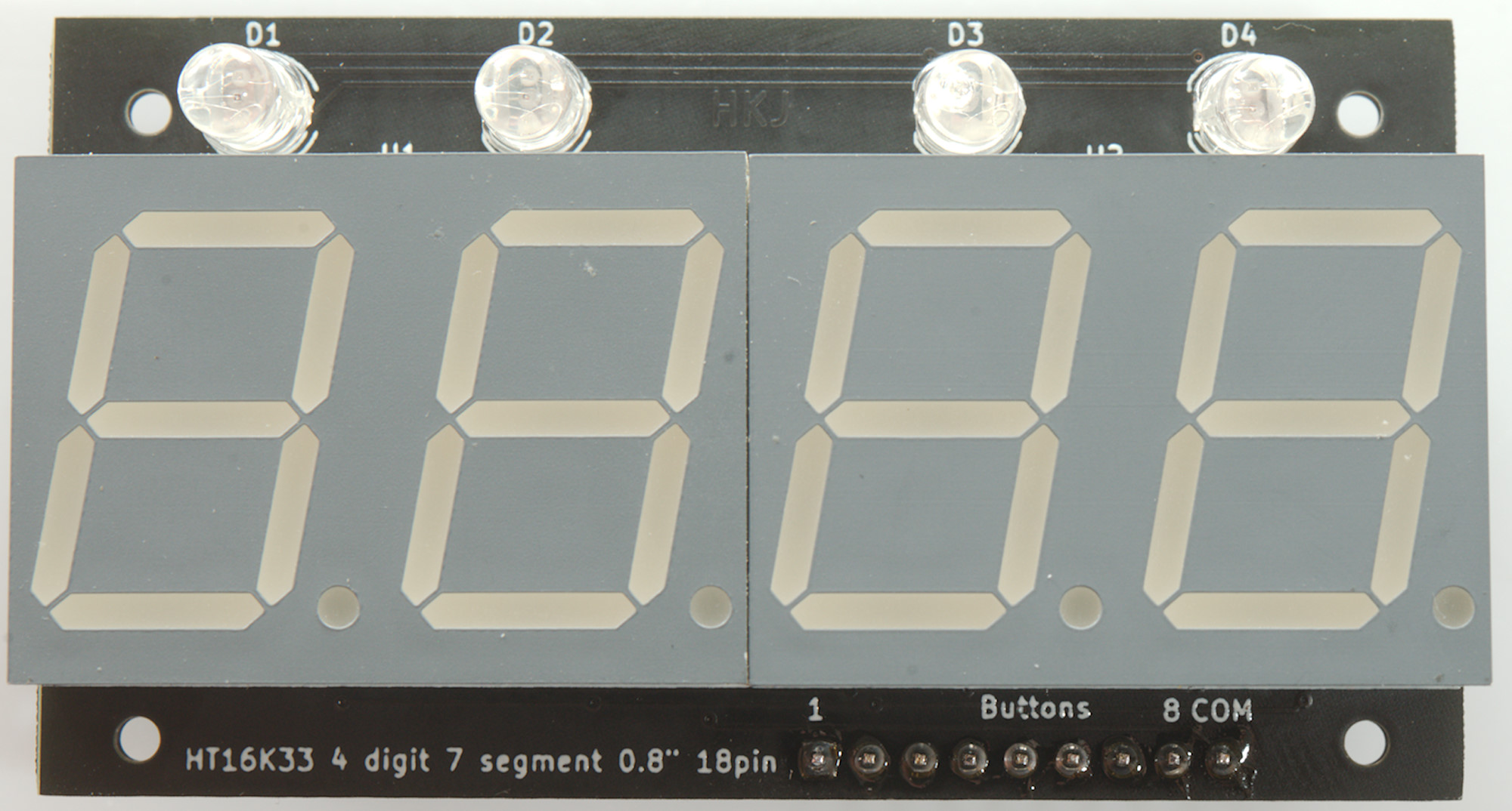
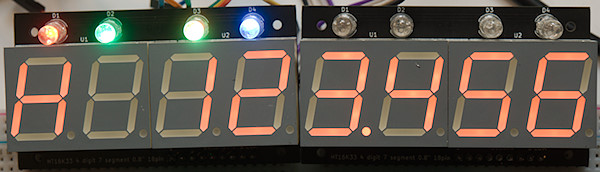
HT16K33 4 digit LED display with indicators (DIY)

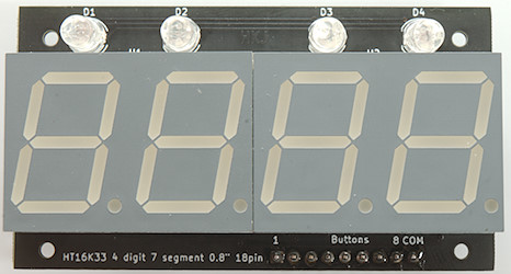
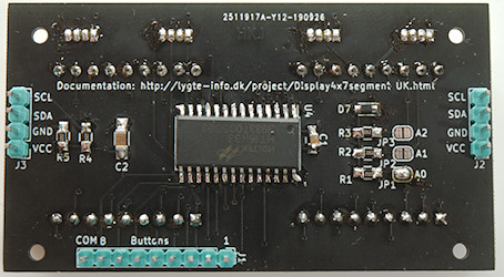
Connections: data=SDA, clock=SCL. All 3 address links are supposed to be open (Address 0x70) for first display.
Display type: _HT16K33_HKJ_4D_
This is a display in my series of DIY modules with RGB indicators and button inputs. The module has one indicator for each digit and can handle 8 buttons, up to 8 modules can be connected in series.
The indicators are called LED_1R, LED_1G, LED_1B, LED2R...LED_3B and the keys are KEY_S1 to KEY_S8. They keys are cleared when read and will first be indicated again 20ms later.
For more information, schematic and gerber files see here
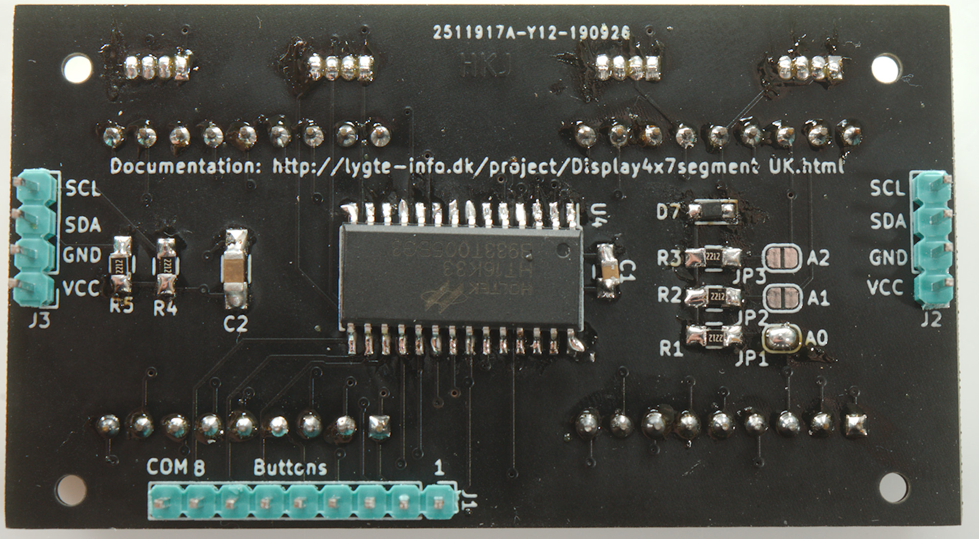
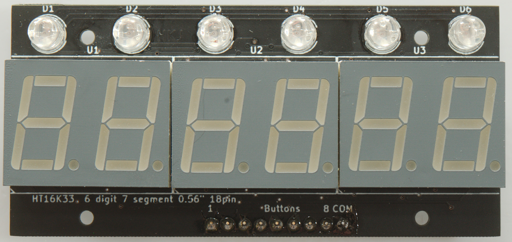
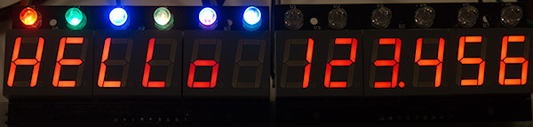
HT16K33 6 digit LED display with indicators (DIY)
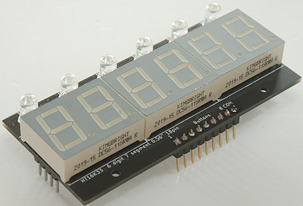
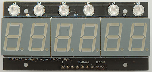
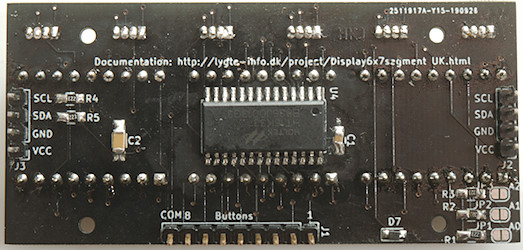
Connections: data=SDA, clock=SCL. All 3 address links are supposed to be open (Address 0x70) for first display.
Display type: _HT16K33_HKJ_6D_
This is a display in my series of DIY modules with RGB indicators and button inputs. The module has one indicator for each digit and can handle 8 buttons, up to 8 modules can be connected in series.
The indicators are called LED_1R, LED_1G, LED_1B, LED2R...LED_5B and the keys are KEY_S1 to KEY_S8. They keys are cleared when read and will first be indicated again 20ms later.
For more information, schematic and gerber files see here
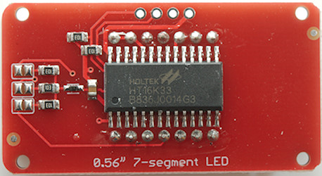
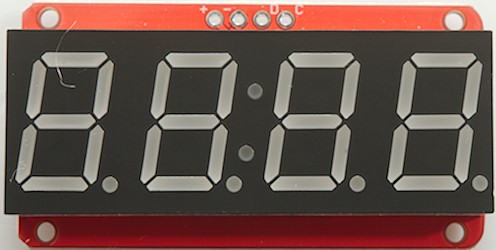
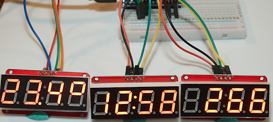
HT16K33 4 digit LED display with colon and point
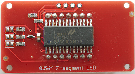
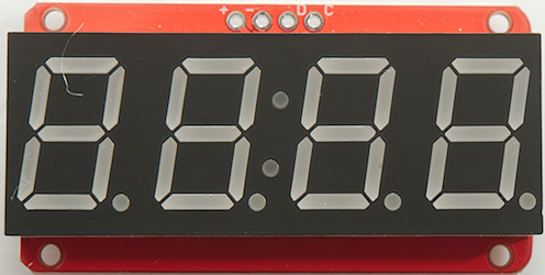
Connections: data=D, clock=C, All 3 address links are supposed to be open (Address 0x70) for fist display.
Display type: _HT16K33_4D_
This display uses a I2C protocol, the driver handles this in software, i.e. any two IO pins can be used to control the display.
This display support both point and colon, the colon is placed on a spare digit. This is hidden in the driver, it is just a 4 digit display with a indicator called COLON_DISP_n where n is display number (First is 0). The driver supports up to 8 display with different address, they will all be handled as one large display with the lowest address starting with digit 0. Remember to increase MAX_DIGITS if more than two displays are used, it must be a multiple of 4.
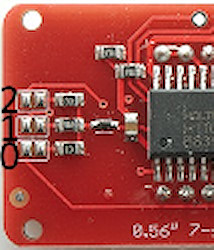
No jumpers is default address, for secondary display short 0, for 3. short 1, for 4. short 0 and 1.
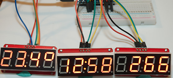
3 displays on a Arduino Nano with temperature, clock and a counter.
Ebay search
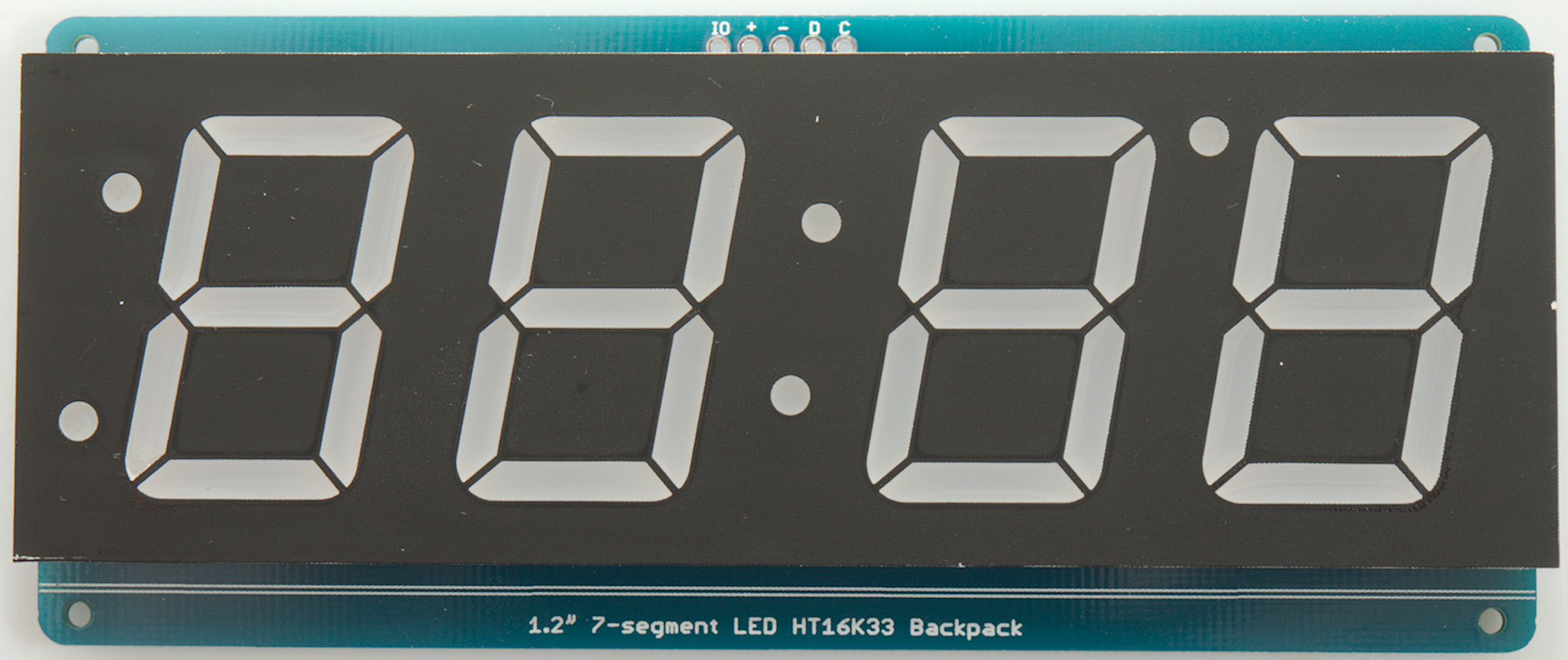
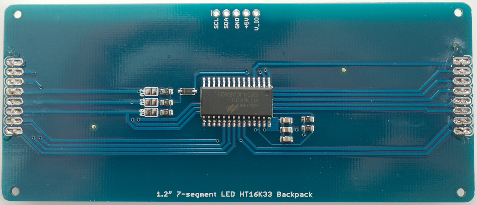
HT16K33 4 digit large LED display with colon and a few indicator dots
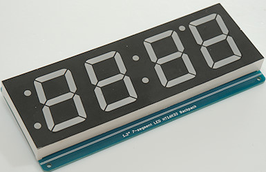

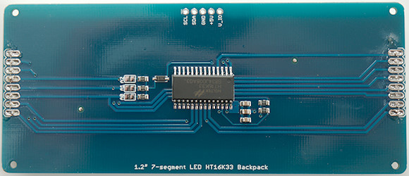
Connections: data=SDA, clock=SCL, V_IO is pullup for 10kOhm resistor on SCA and SDA. All 3 address links are supposed to be open (Address 0x70) for fist display.
Display type: _HT16K33_4DL_
This display uses a I2C protocol, the driver handles this in software, i.e. any two IO pins can be used to control the display.
This display has a colon and 3 indicator dots, they are all placed on a spare digit. This is hidden in the driver, it is just a 4 digit display with a indicators called COLON_DISP_n, DOT_FT_DISP_n, DOT_FB_DISP_n and DOT_LT_DISP_n (F=Front, L=Last, T=Top, B=Bottom) where n is display number (First is 0). The driver supports up to 8 display with different address, they will all be handled as one large display with the lowest address starting with digit 0. Remember to increase MAX_DIGITS if more than two displays are used, it must be a multiple of 4.
Ebay link
HT16K33 8 digit LED display
Connections: data=SDA, clock=SCL, V_I is pullup for I2C and VCC is power for display, on 5V systems both are connected to 5V. All 3 address links are supposed to be open (Address 0x70).
Display type: _HT16K33_8D_
This display uses a I2C protocol, the driver handles this in software, i.e. any two IO pins can be used to control the display.
The displays are in sockets, this makes it possible to swap them for other colors, but it also means they are slightly unstable in the mounting.
The driver supports up to 8 display with different address (Short A0, A1 and/or A2), they will all be handled as one large display with the lowest address starting with digit 0. Remember to increase MAX_DIGITS if more than one displays are used, it must be a multiple of 8.
Ebay search
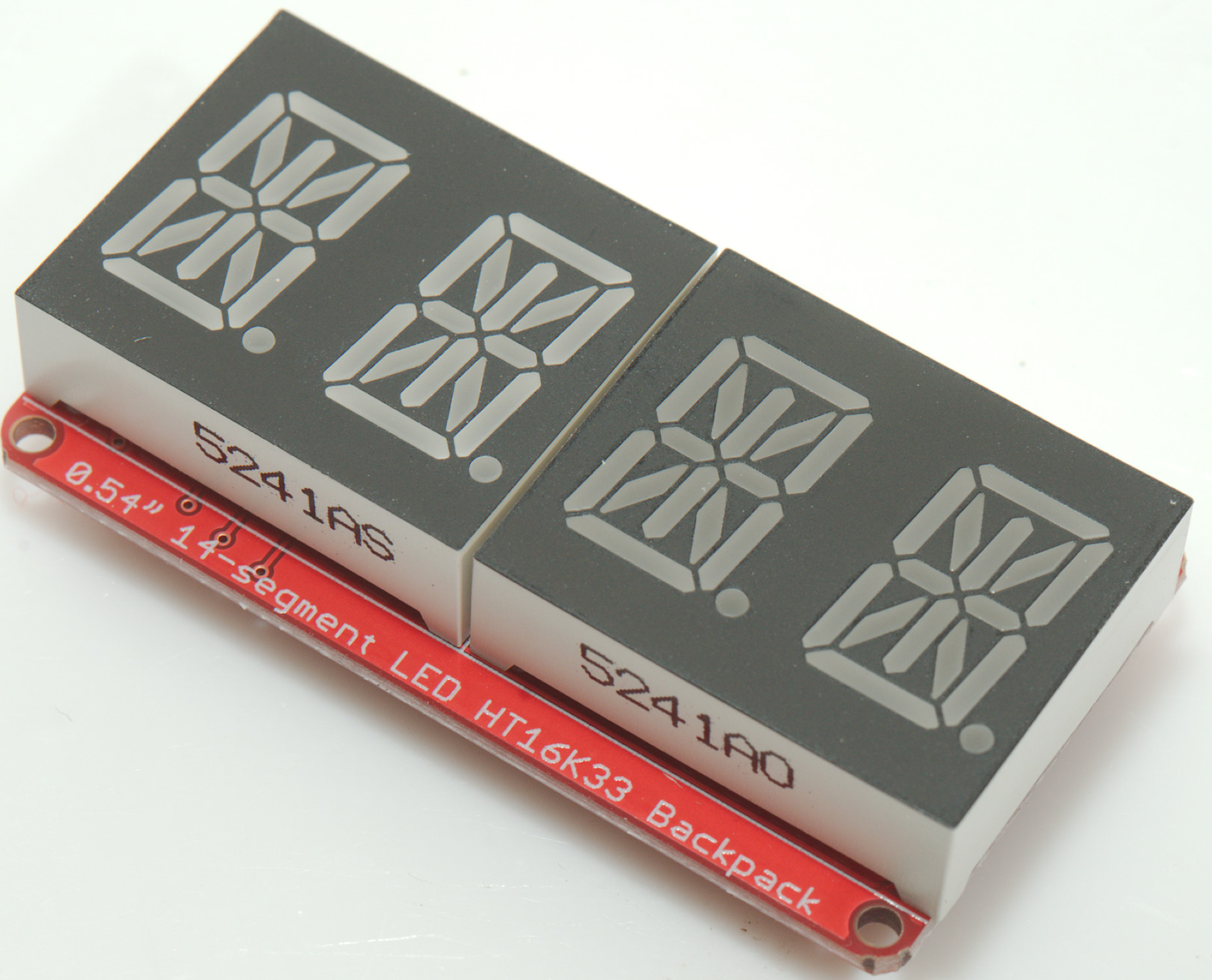
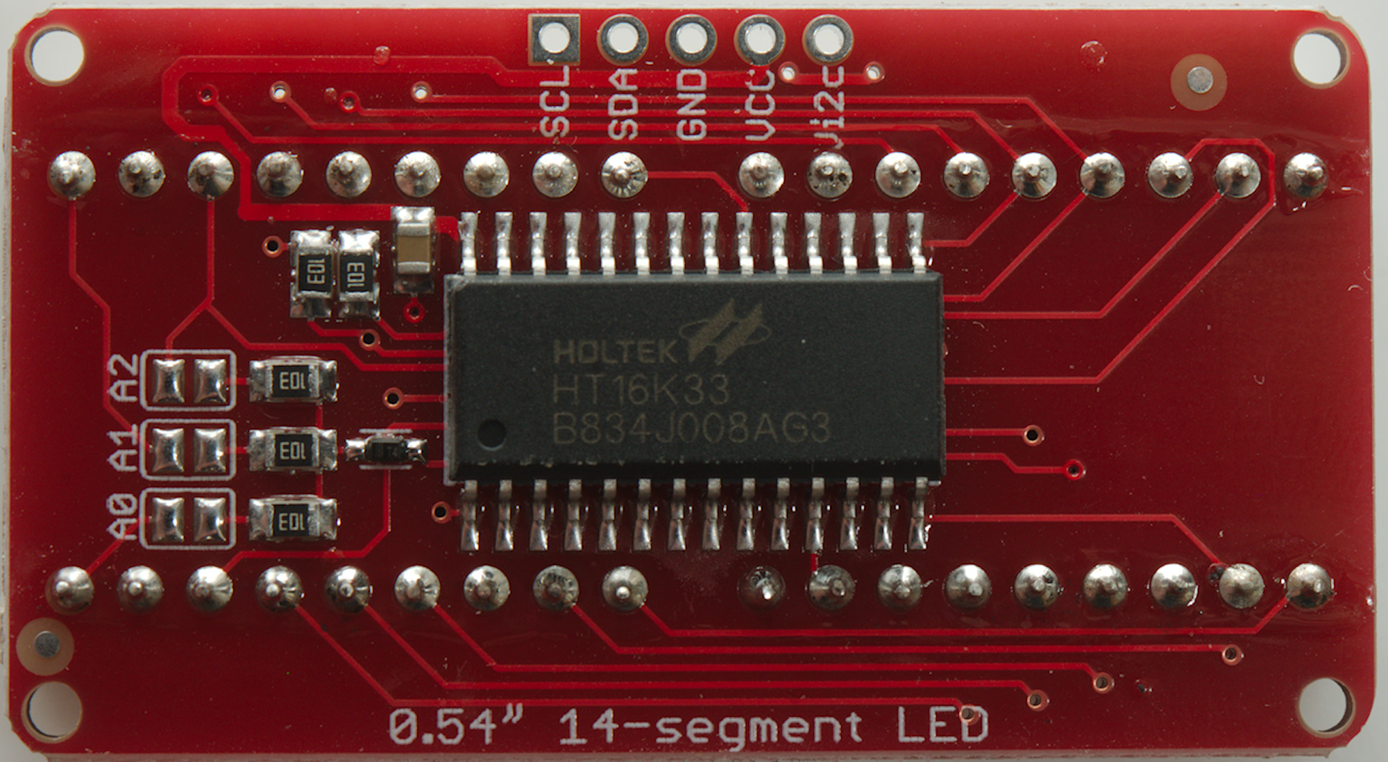
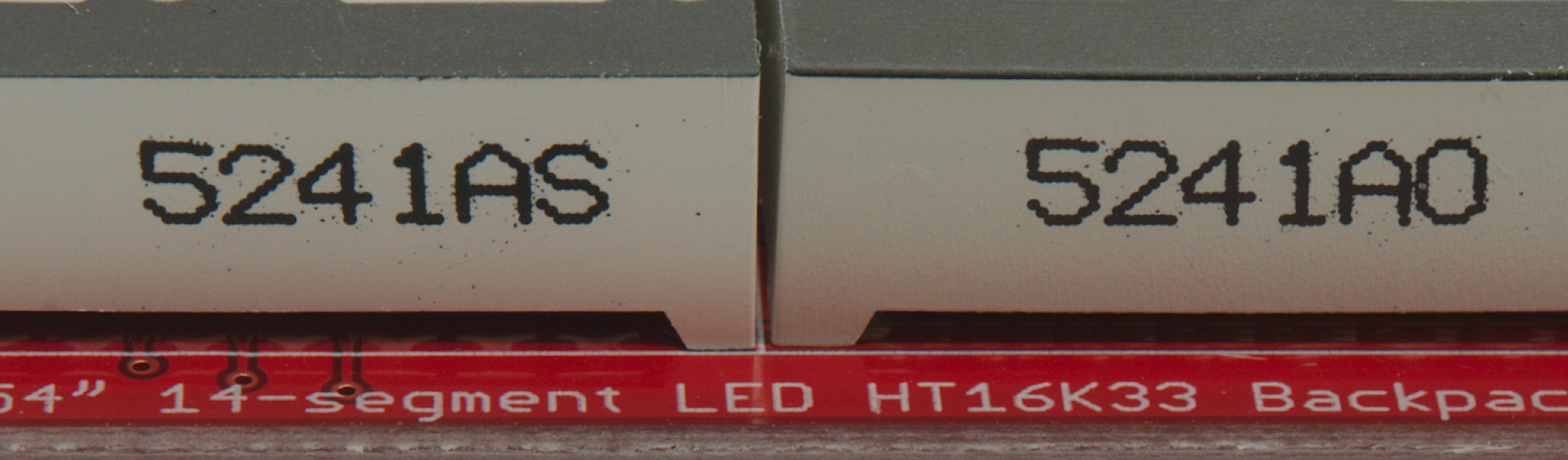
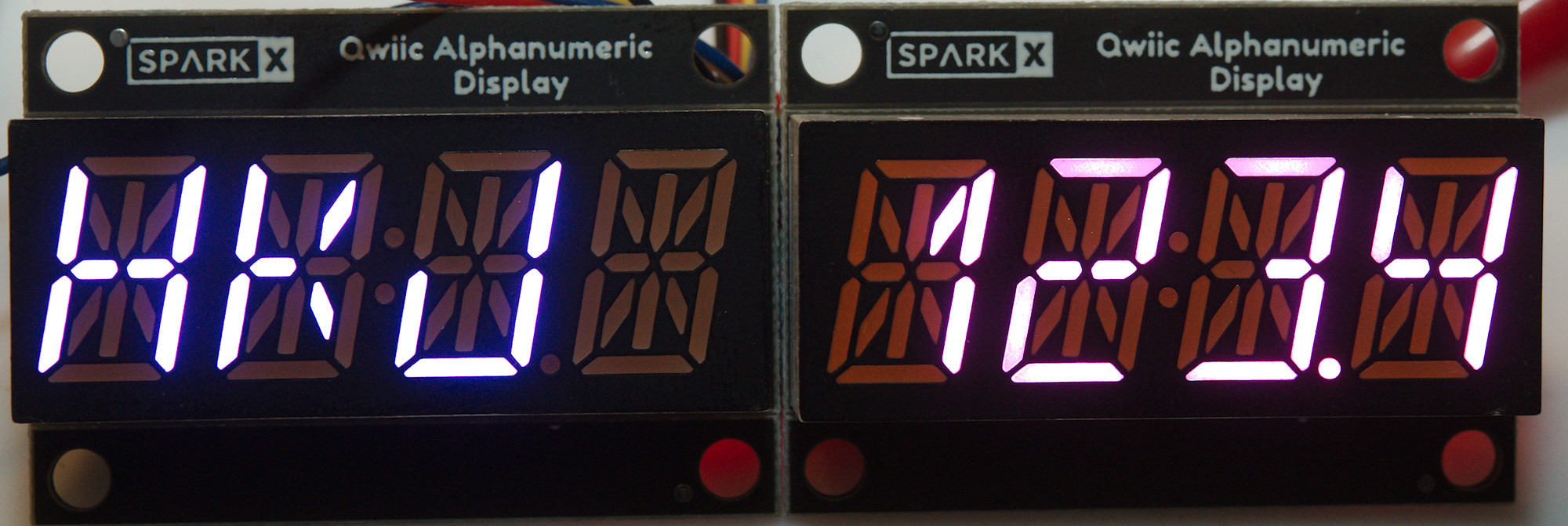
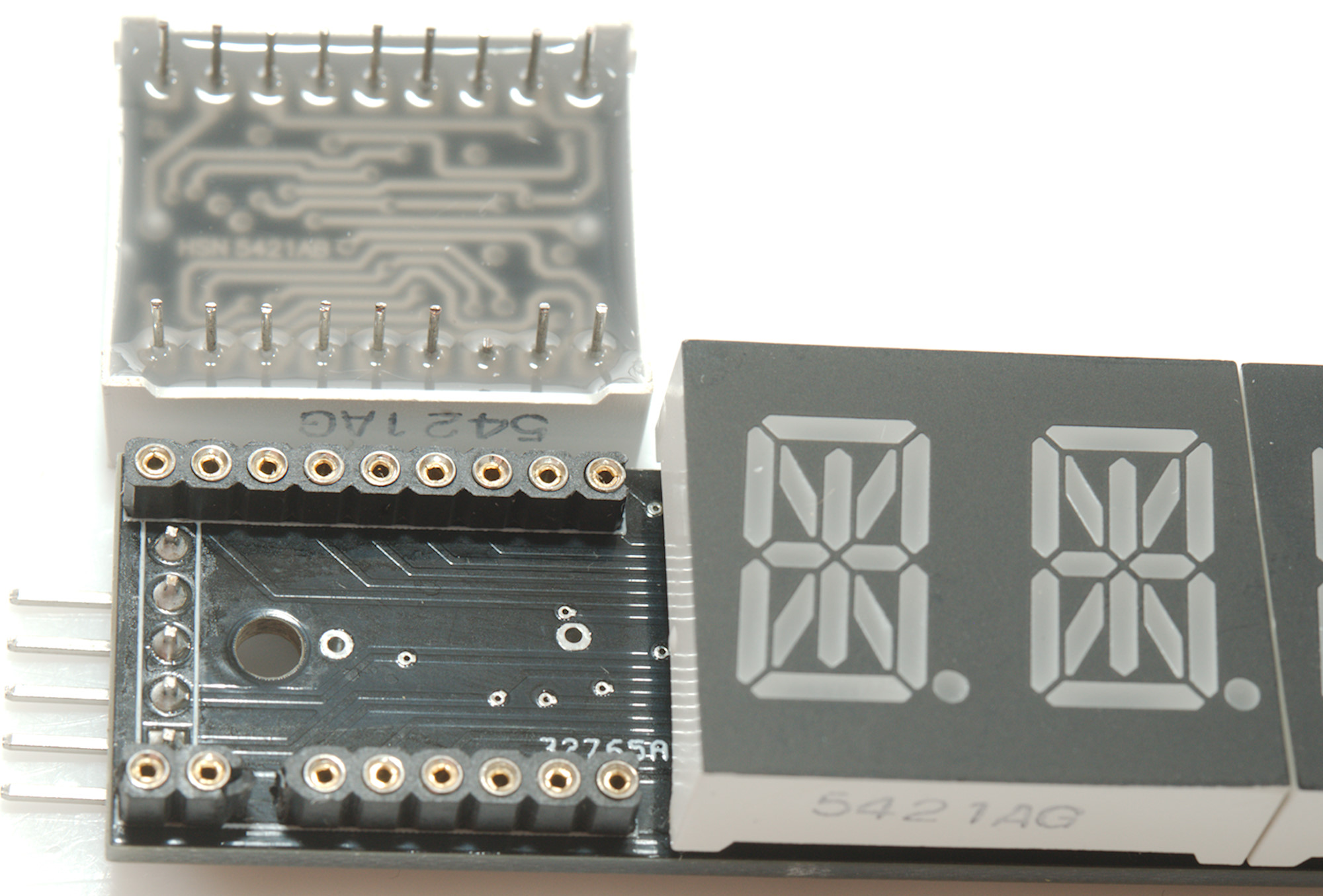
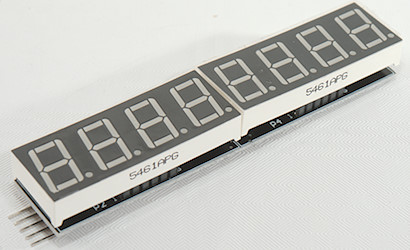
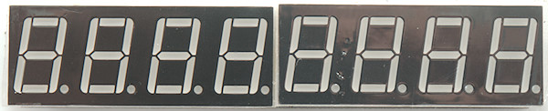
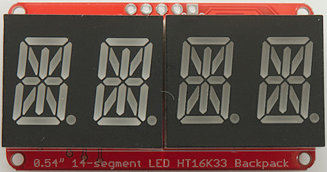
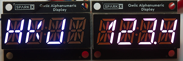
HT16K33 4 digit 14-segment LED display
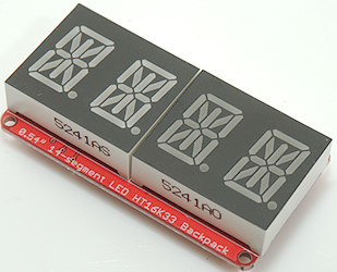
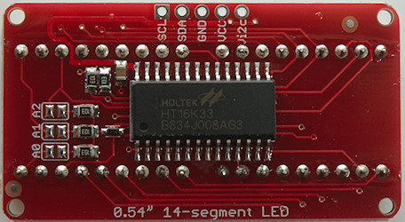
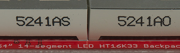
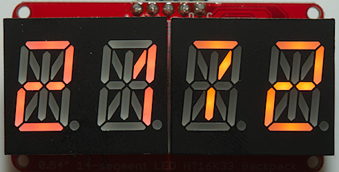
In the typical Ebay offering the two displays are not the same color, here is a red and a orange.
Connections: data=SDA, clock=SCL, Vi2c is pullup for I2C and VCC is power for display, on 5V systems both are connected to 5V. All 3 address links are supposed to be open (Address 0x70) for first display.
Display type: _HT16K33_14SEG_4D_ (Both 4D and 8D works for a single display).
This display uses a I2C protocol, the driver handles this in software, i.e. any two IO pins can be used to control the display.
The driver supports up to 8 display with different address (Short A0, A1 and/or A2), they will all be handled as one large display with the lowest address starting with digit 0. Remember to increase MAX_DIGITS if more than two displays are used, it must be a multiple of 4.
Ebay search
HT16K33 4 digit 14-segment LED display, SparkFun QWIIC SPX-16xxx
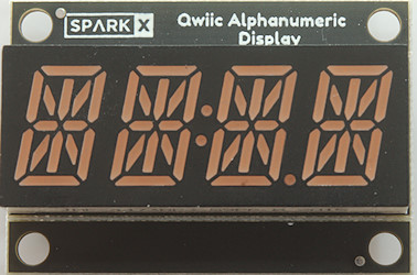
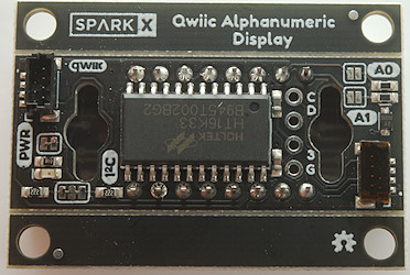
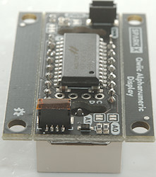
Connections: data=SDA, clock=SCL, the QWIIC system is rated for 3.3V, but display driver chip is a 5V only chip.
Display type: _HT16K33_14SEG_4DS_
This display uses a I2C protocol, the driver handles this in software, i.e. any two IO pins can be used to control the display.
The display uses a 9x8 matrix for the display with row/columns swapped, this is handle transparently by the driver.
The driver supports up to 4 display with different address (Short A0 and/or A1), they will all be handled as one large display with the lowest address starting with digit 0. Remember to increase MAX_DIGITS if more than two displays are used, it must be a multiple of 4.
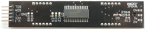
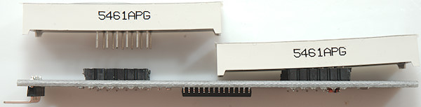
HT16K33 4 digit 16-segment LED display (DIY)
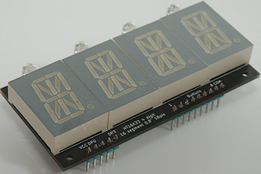
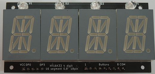
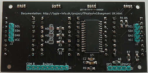

Connections: data=SDA, clock=SCL. All 3 address links are supposed to be open (Address 0x70) for first display.
Display type: _HT16K33_16SEG_HKJ_4D_ or _HT16K33_16SEG_HKJ_4DW_
The display can me mounted with RGB leds as indicators and supports up to 8 external keys. For easy chaining there are two data connectors, one for input and one for output (Either can be used, they are in parallel). There are 8 possible addresses, i.e. 8 displays are possible on the same two communication wires. The indicators and keys will only work on the first module (for now).
These display uses 16 segments for the numbers and letters, this means there is no space for a decimal point in a 16 bit buffer or driver. I have added a extra connector to the display connected for the decimal points, it can be linked for a fixed point or controlled from Arduino. If using the W version of the driver, it can directly control the extra Arduino pins for decimal points, but the price is a 32 bit buffer for each digit. A special constructor for the driver must be used:
Code:
byte decimalPointPins[] = {2, 3, 4, 5};// List MSB first
LEDDisplayDriver display(dataPin, clockPin, loadPin, decimalPointPins, autoUpdate, numberOfDigits);
The indicators are called LED_1R, LED_1G, LED_1B, LED2R...LED_5B and the keys are KEY_S1 to KEY_S8. They keys are cleared when read and will first be indicated again 20ms later.
For more information, schematic and gerber files see here
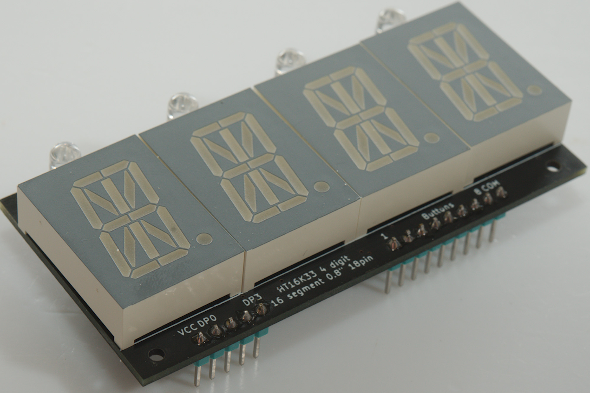
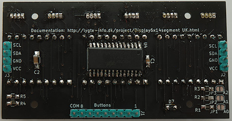
HT16K33 6 digit 14-segment LED display 8 bit digits (DIY)
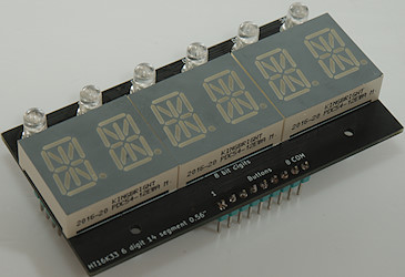
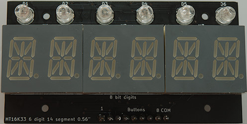
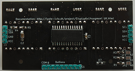
Connections: data=SDA, clock=SCL. All 3 address links are supposed to be open (Address 0x70) for first display.
Display type: _HT16K33_14SEG_HKJ_6D8_
The display can me mounted with RGB leds as indicators and supports up to 8 external keys. For easy chaining there are two data connectors, one for input and one for output (Either can be used, they are in parallel). There are 8 possible addresses, i.e. 8 displays are possible on the same two communication wires. The indicators and keys will only work on the first module (for now).
The indicators are called LED_1R, LED_1G, LED_1B, LED2R...LED_5B and the keys are KEY_S1 to KEY_S8. They keys are cleared when read and will first be indicated again 20ms later.
This display module uses displays with a 8 bit interface, see below for a more common 15 bit interface.
For more information, schematic and gerber files see here
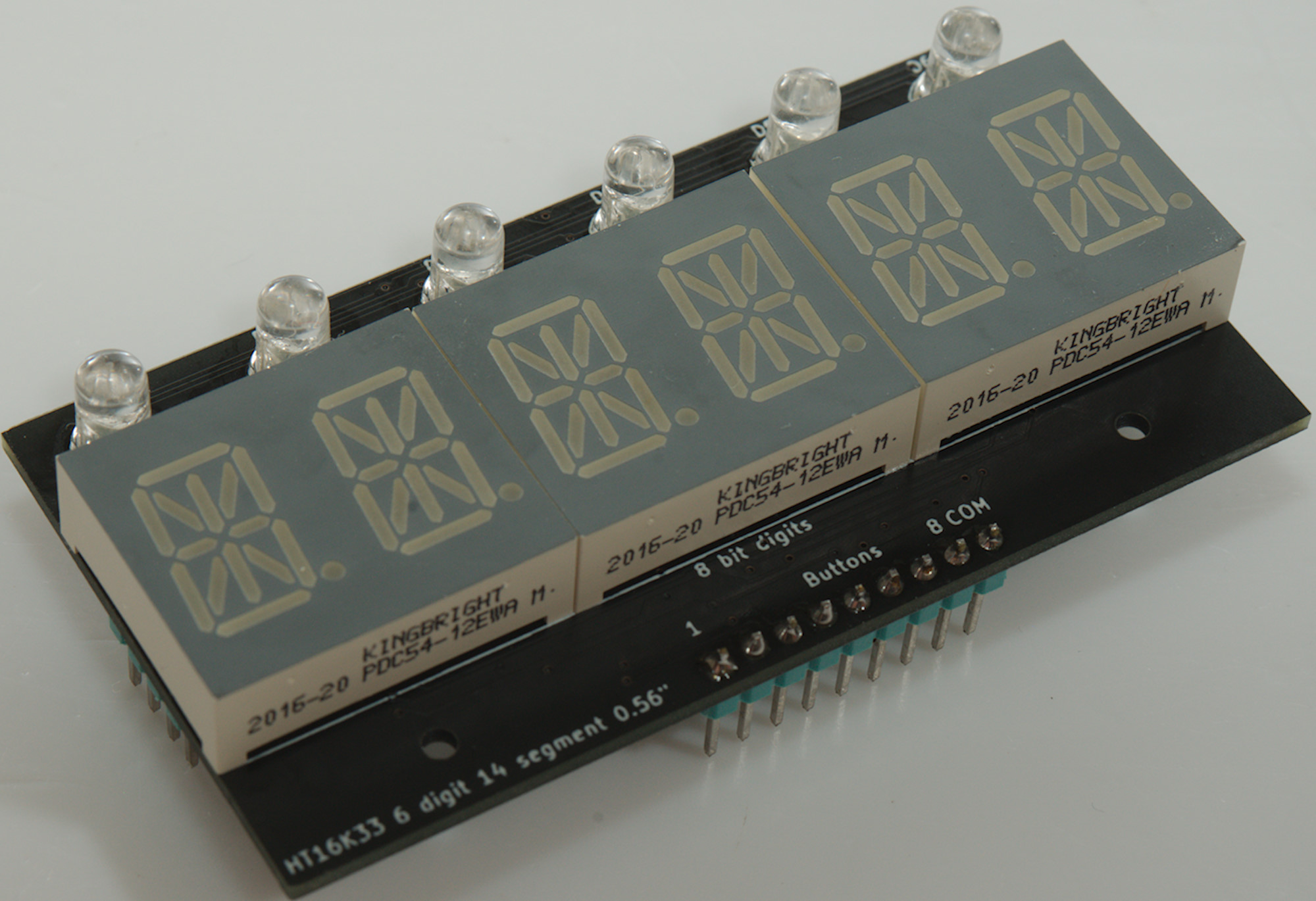
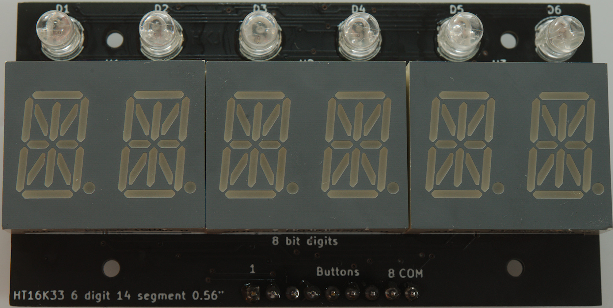
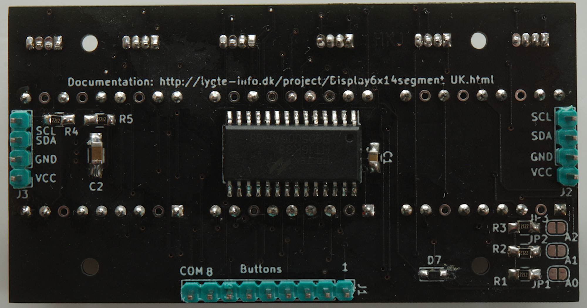
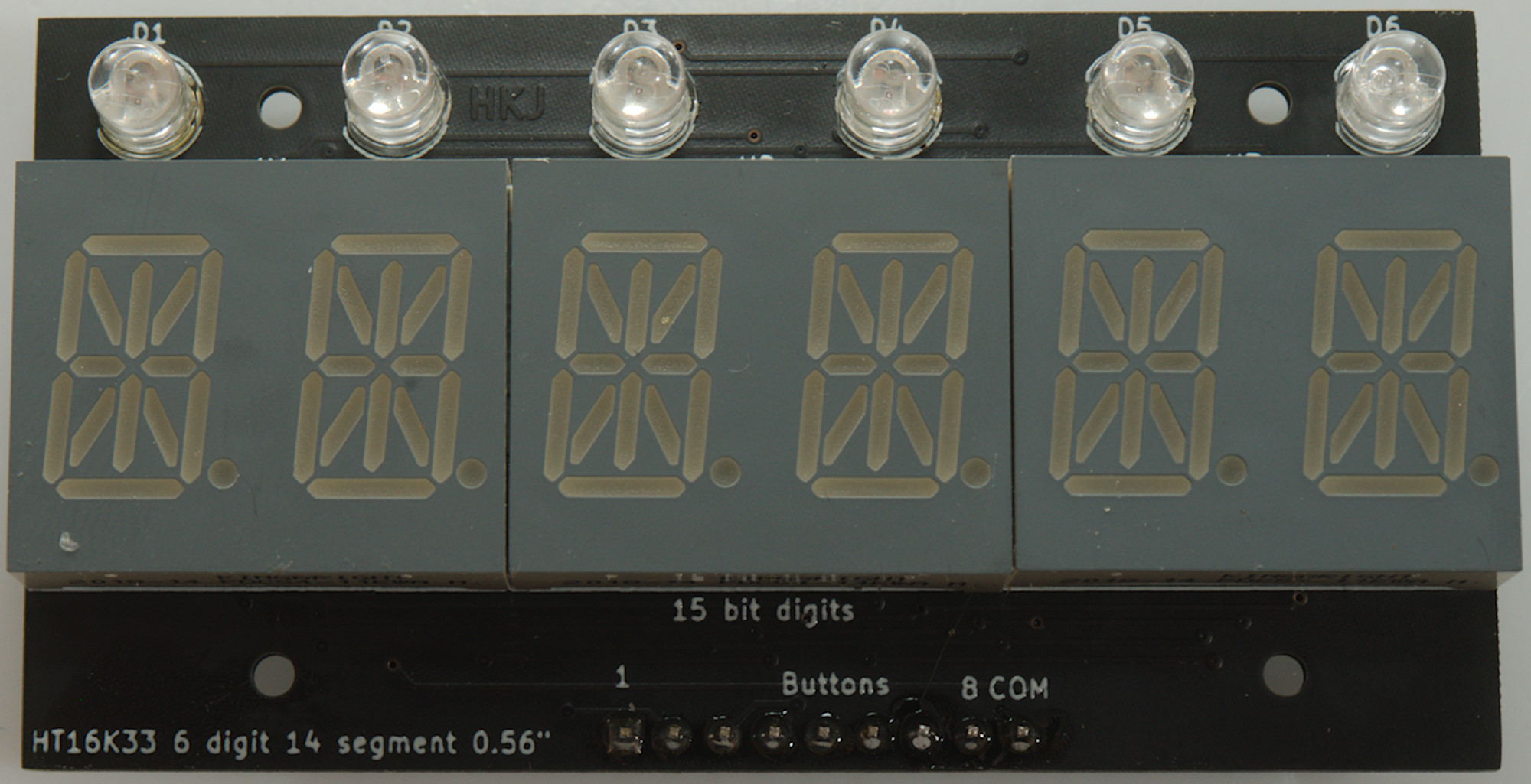
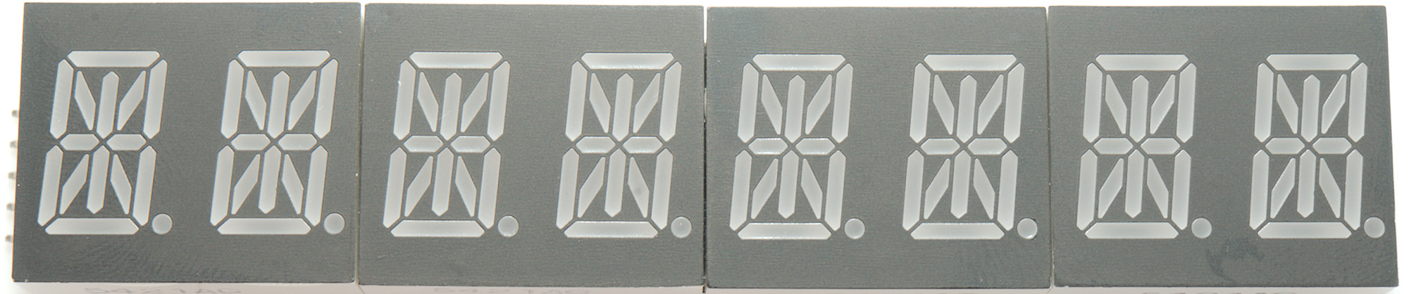
HT16K33 6 digit 14-segment LED display 15 bit digits (DIY)
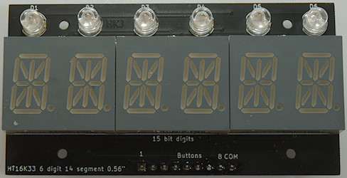
Connections: data=SDA, clock=SCL. All 3 address links are supposed to be open (Address 0x70) for first display.
Display type: _HT16K33_14SEG_HKJ_6D_
The display can me mounted with RGB leds as indicators and supports up to 8 external keys. For easy chaining there are two data connectors, one for input and one for output (Either can be used, they are in parallel). There are 8 possible addresses, i.e. 8 displays are possible on the same two communication wires. The indicators and keys will only work on the first module (for now).
The indicators are called LED_1R, LED_1G, LED_1B, LED2R...LED_5B and the keys are KEY_S1 to KEY_S8. They keys are cleared when read and will first be indicated again 20ms later.
This display module uses displays with a 15 bit interface.
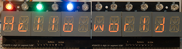
Two modules chained.
For more information, schematic and gerber files see here
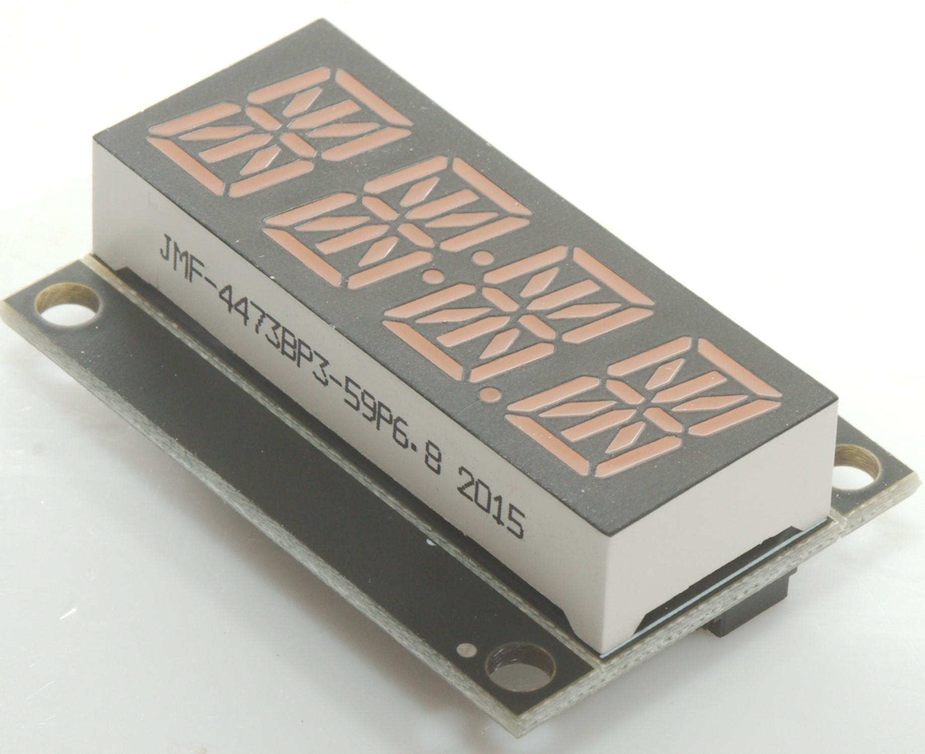
HT16K33 8 digit 14-segment LED display

Connections: data=SDA, clock=SCL, V_I is pullup for I2C and VCC is power for display, on 5V systems both are connected to 5V. All 3 address links are supposed to be open (Address 0x70) for first display.
Display type: _HT16K33_14SEG_8D_
This display uses a I2C protocol, the driver handles this in software, i.e. any two IO pins can be used to control the display.
The displays are in sockets, this makes it possible to swap them for other colors and get access to the mounting holes.
The driver supports up to 8 display with different address (Short A0, A1 and/or A2), they will all be handled as one large display with the lowest address starting with digit 0. Remember to increase MAX_DIGITS if more than one displays are used, it must be a multiple of 8.
Ebay search
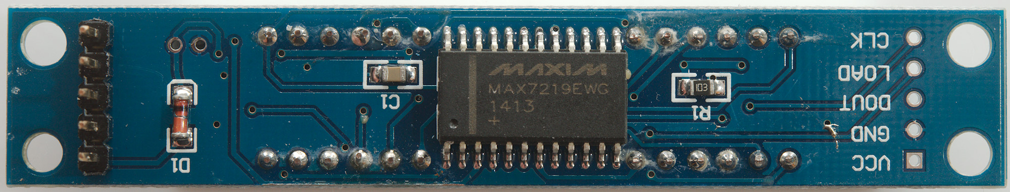
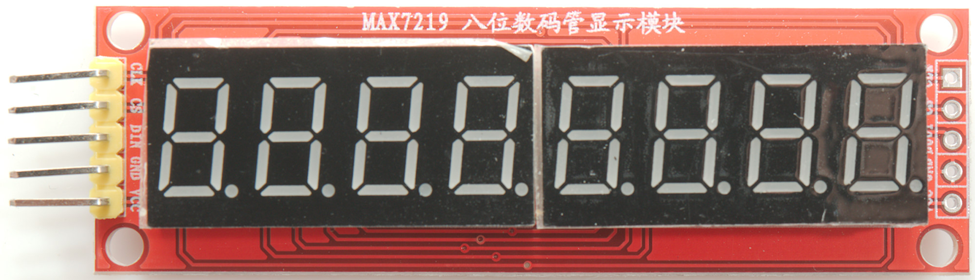
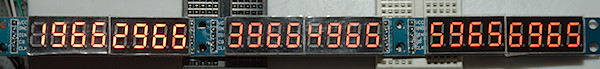
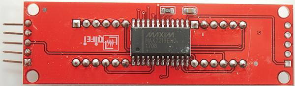
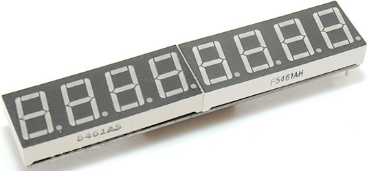
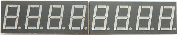
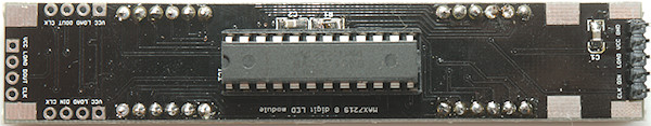
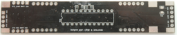
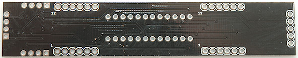
MAX7219 8 or more digit
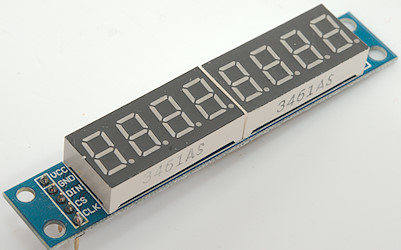
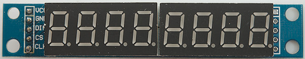
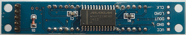
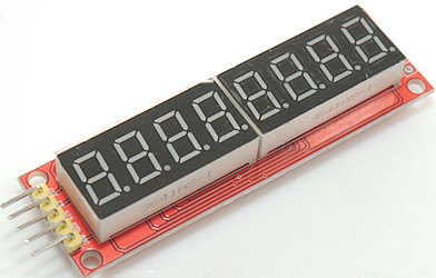
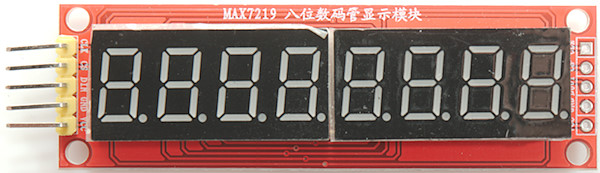
Connections: data=DIN, clock=CLK, load=CS
Display type: _MAX7219_
The MAX7219, usual sold with 8 digits connected. The library do not use the 7 segment decoder in the chip, but directly controls the segment.

Multiple MAX7219 chained together, for this to work the frame buffer must be increased (MAX_DIGITS), one byte is needed for each digit, i.e. 24 for the above display. With this size display it is best to run without auto update and first call update after updating all the numbers.
Ebay search Aliexpress search
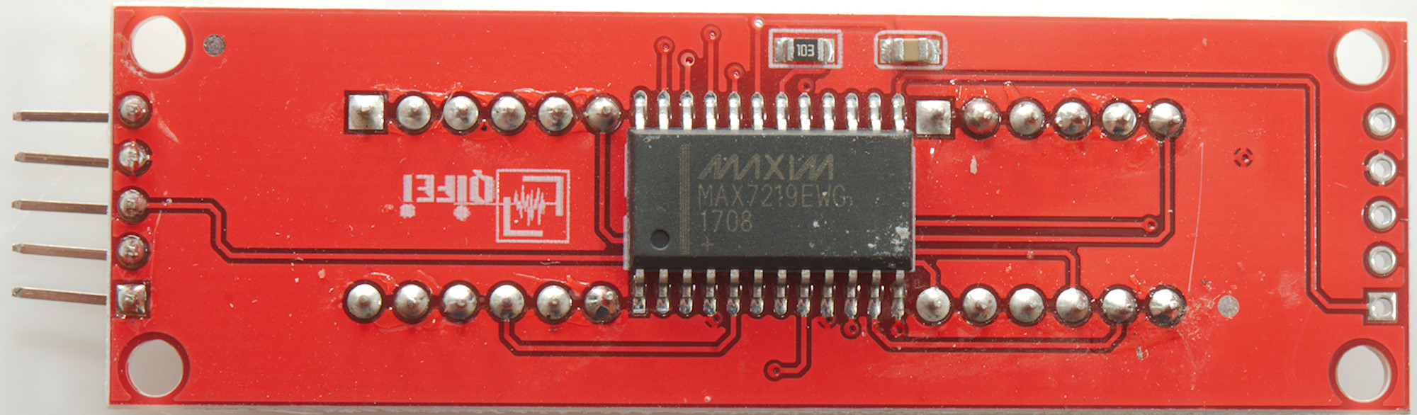
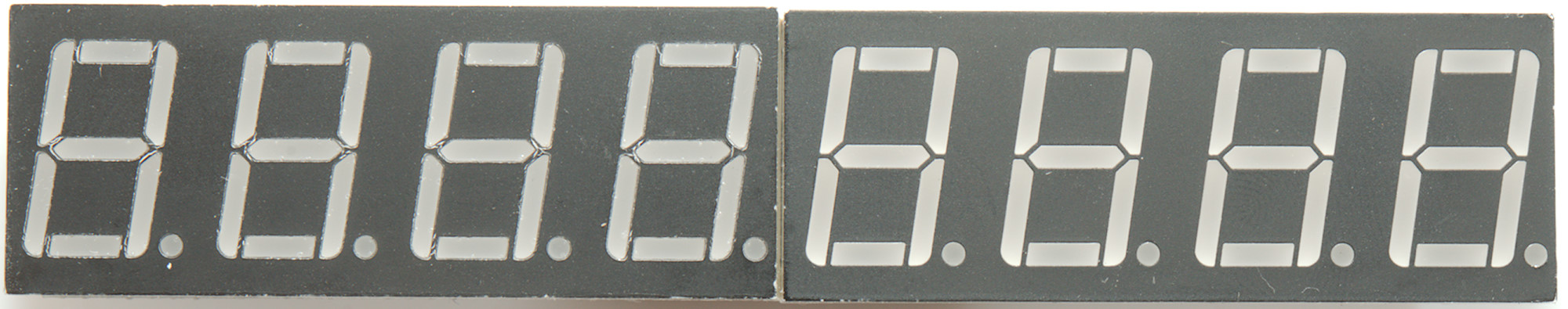
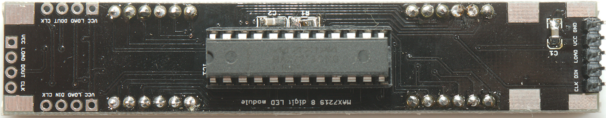
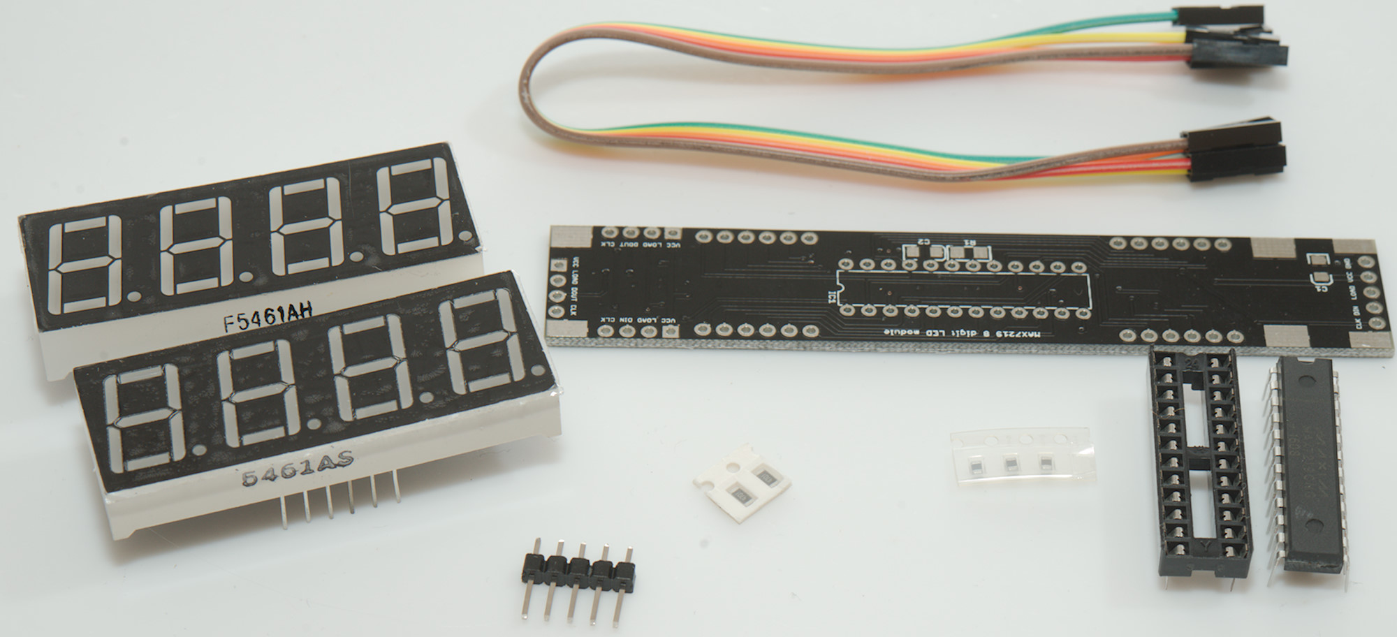
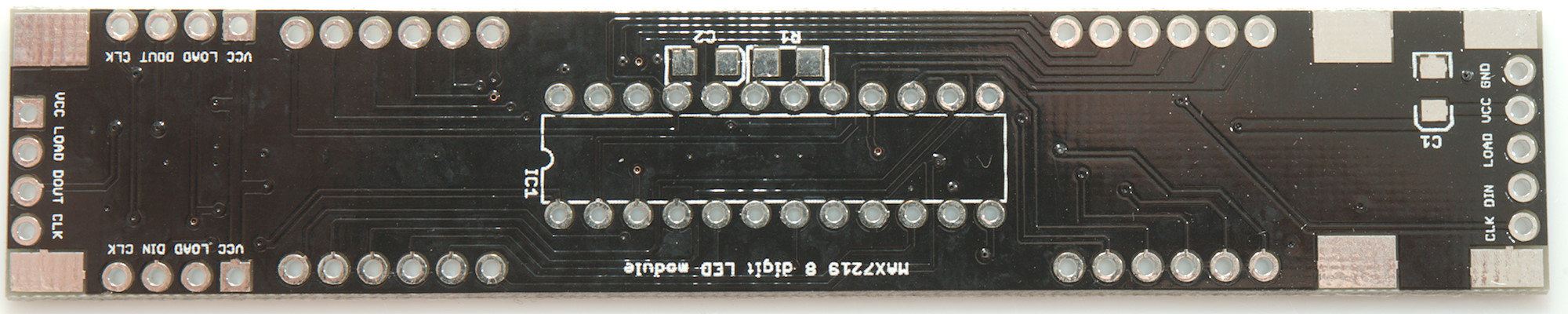
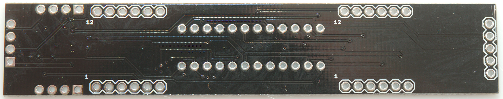
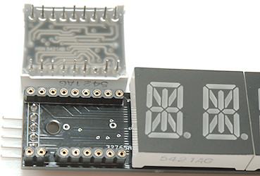
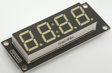
MAX7219 8 or more digit with 0.56" digits
Connections: data=DIN, clock=CLK, load=LOAD
Display type: _MAX7219_
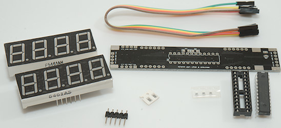
This display is sold as a kit and it is possible to select digit color. The supplied resistor has a fairly low value (4.7kOhm), this is outside the MAX7219 specifications. The two displays sits very close together. The display do not have any mounting holes.
It is possible to chain multiple displays together and the circuit board is designed for it.
Ebay link
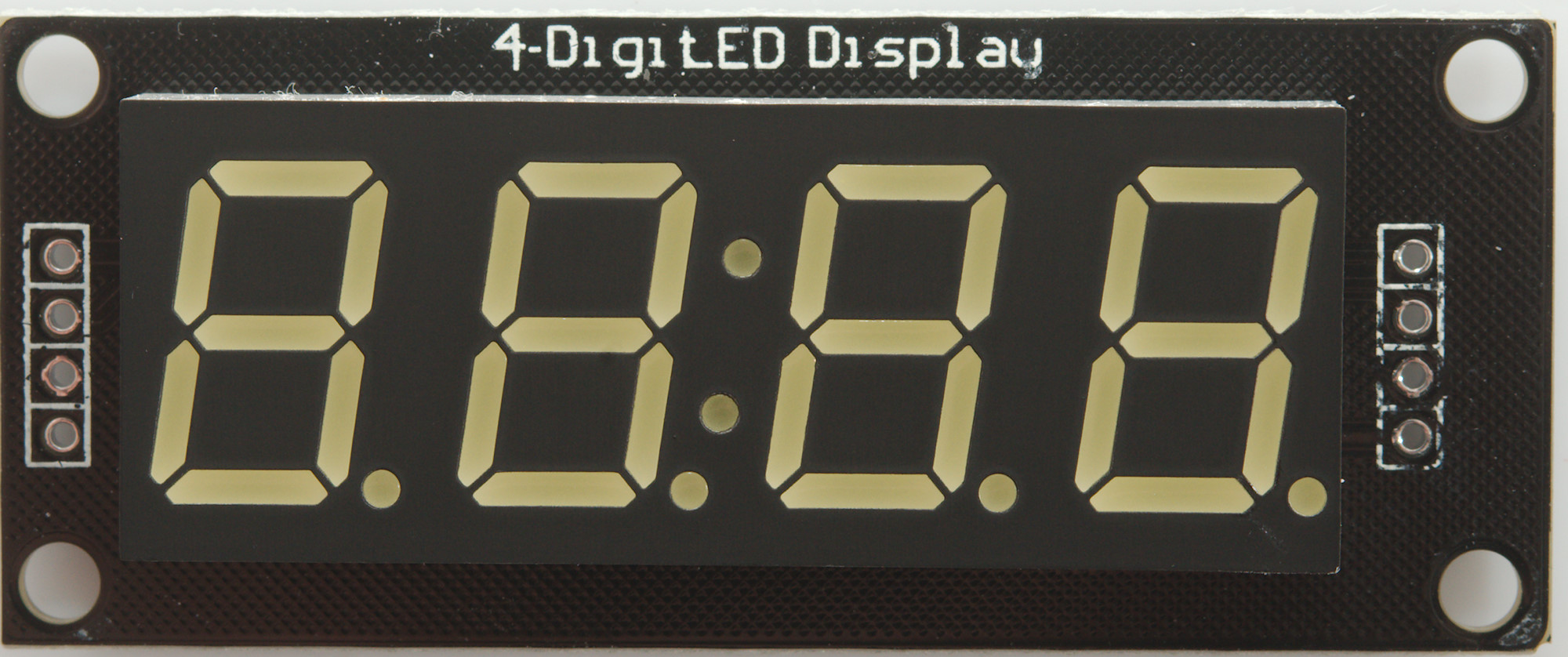
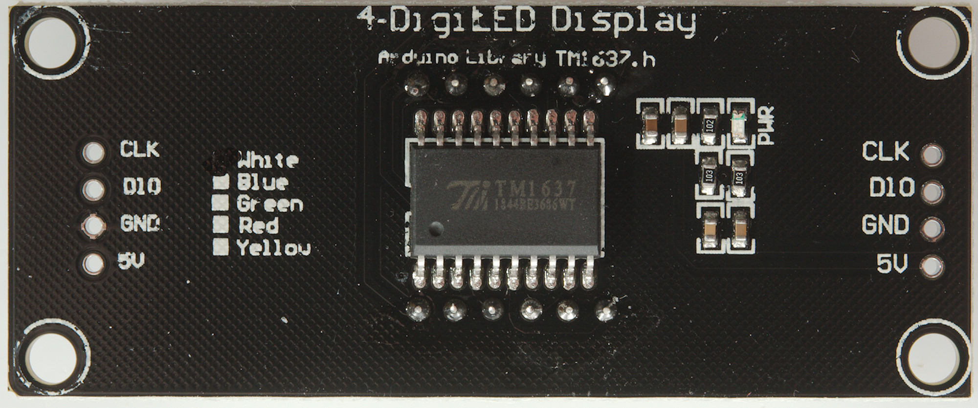
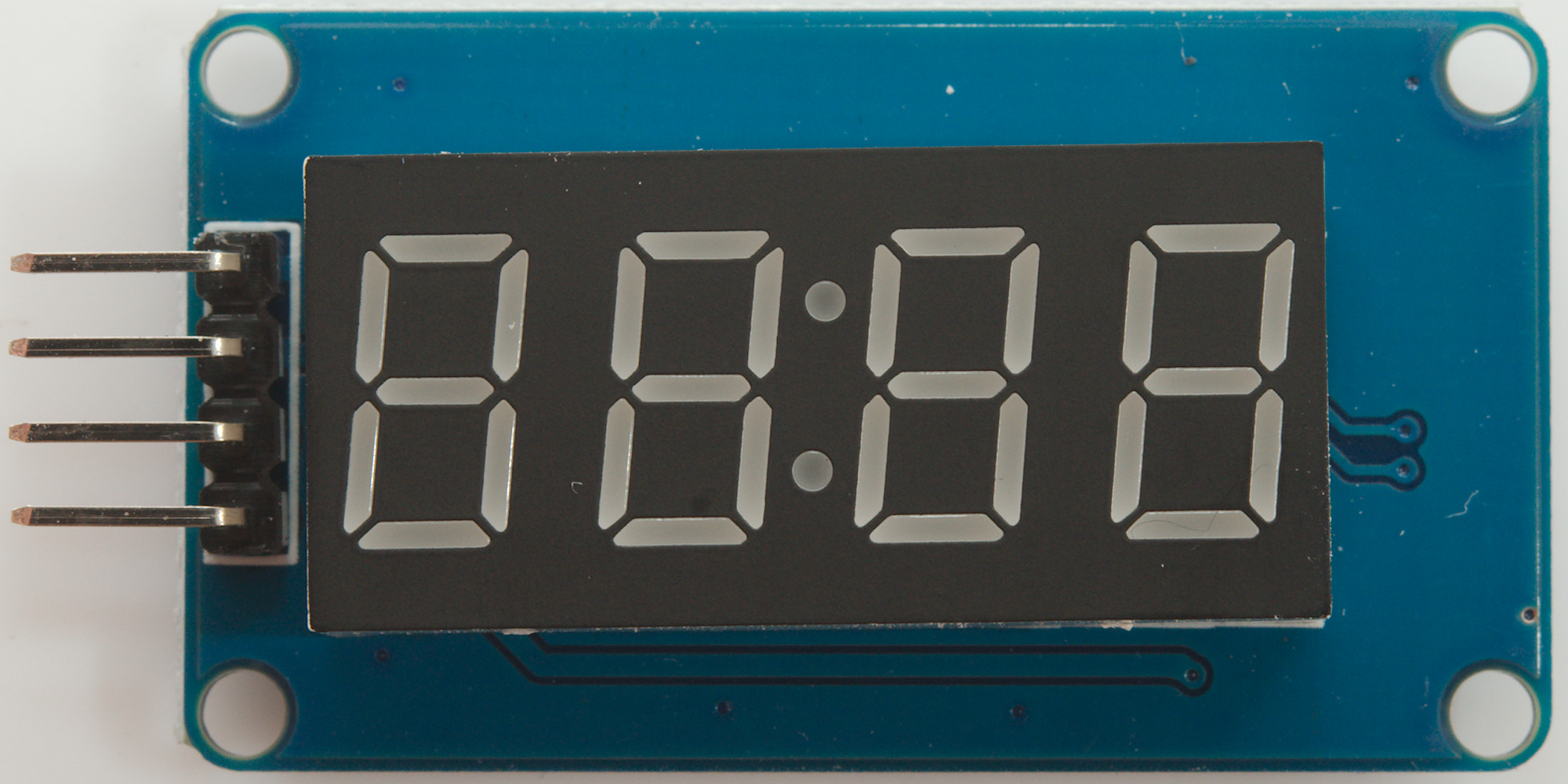
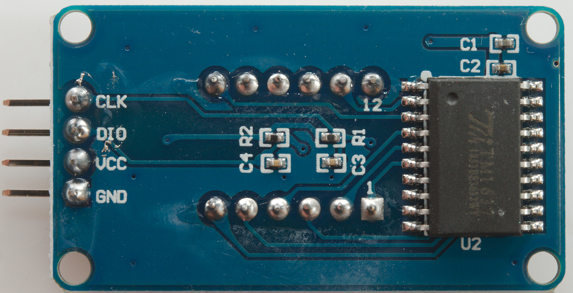
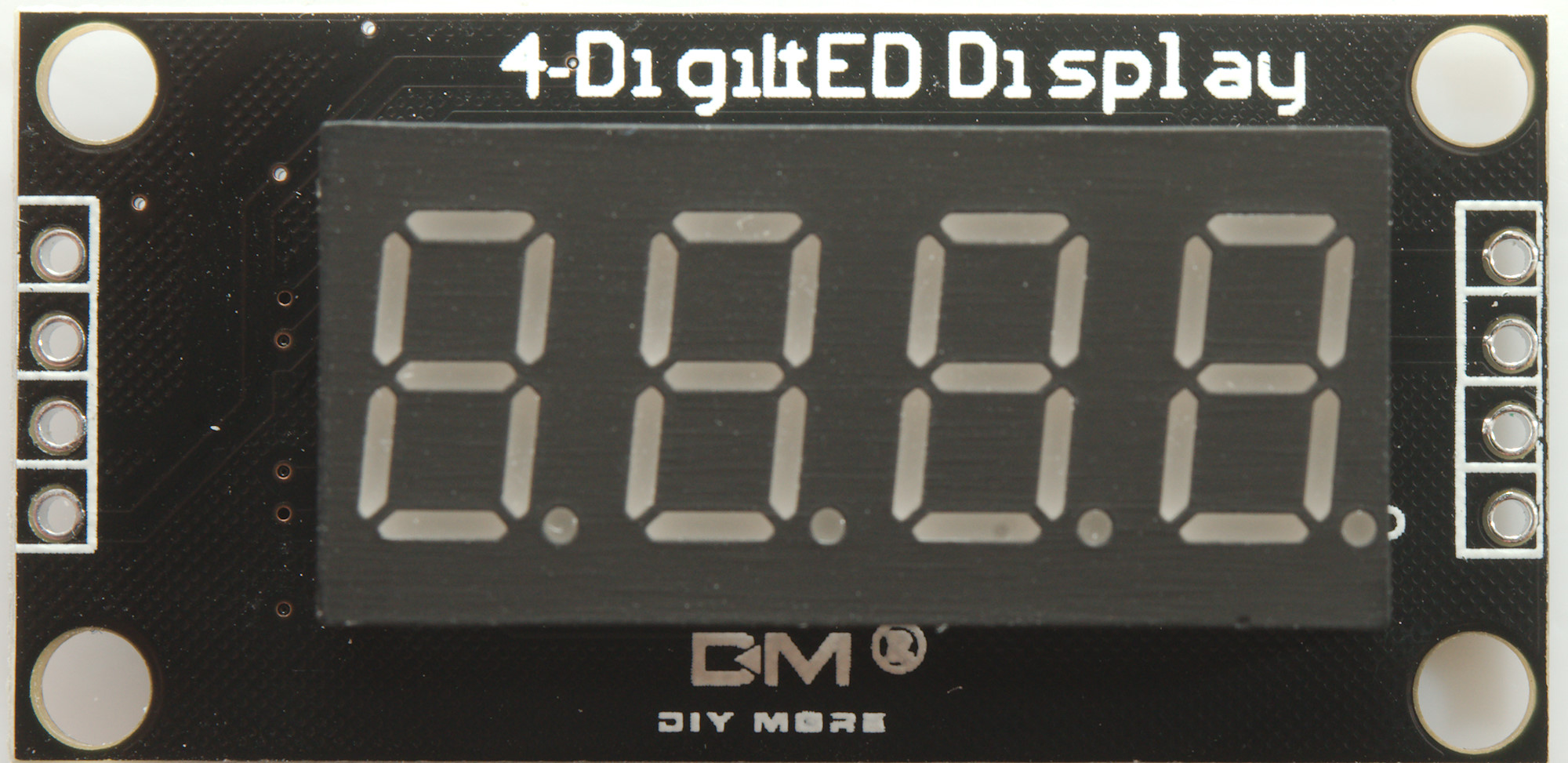
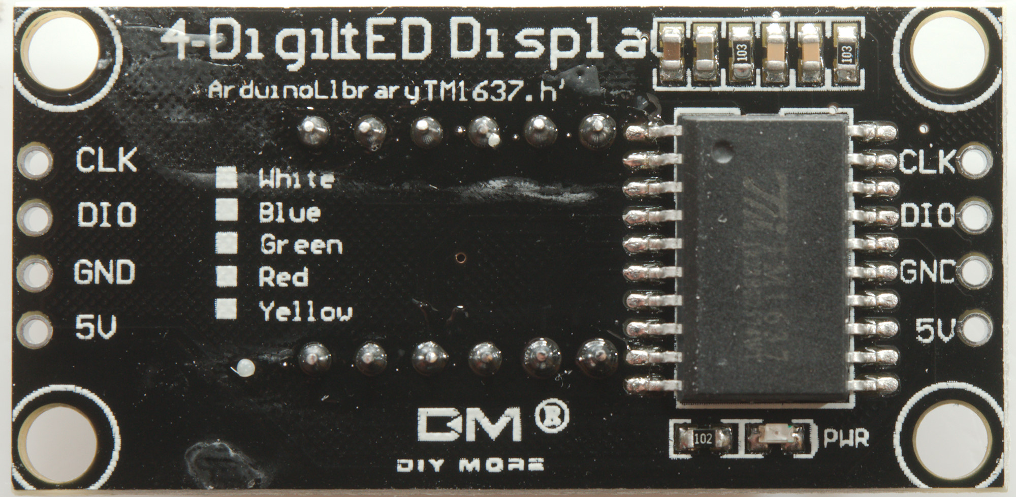
TM1637 4 digit
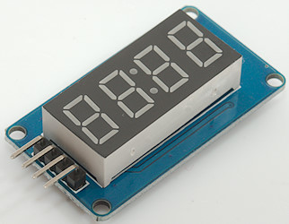
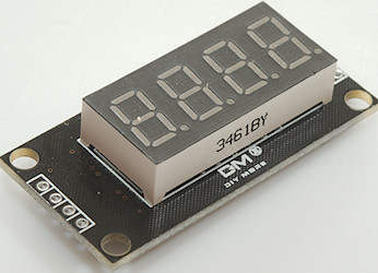
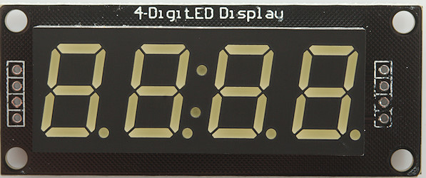
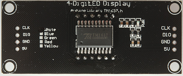
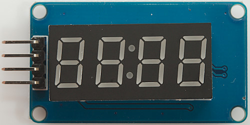
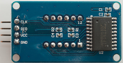
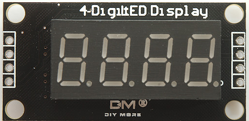
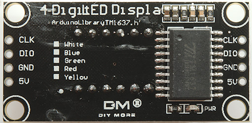
Connections: data=DIO, clock=CLK
Display type: _TM1637_ or _TM1637_COLON_
These displays only needs two connections. Many displays are designed for clock usage, i.e. the decimal points are not connected, but it is possible to find some displays with working decimal points. There is two versions of this chip with slightly different protocol timing, the one implemented here works with both.
The driver called "_TM1637_COLON_" uses display.setIndicators(COLON_DISP_0) to control the colon and prevents any decimal point from interfering with it, on the "_TM1637_" driver the decimal point is supported and is used for display with working decimal points.
Ebay search Aliexpress search
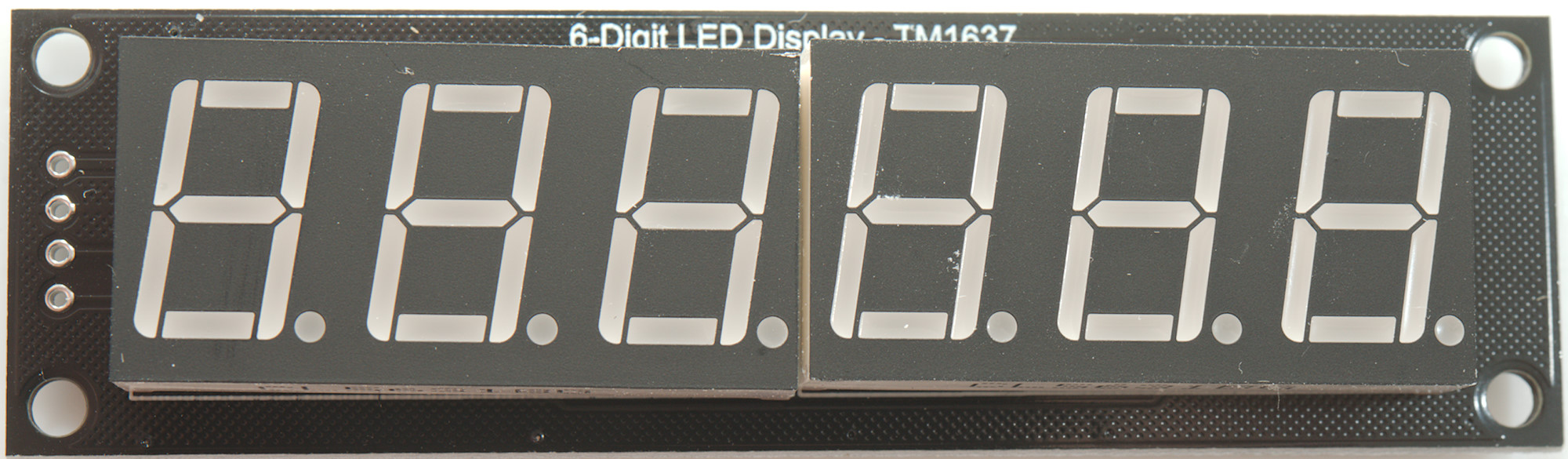
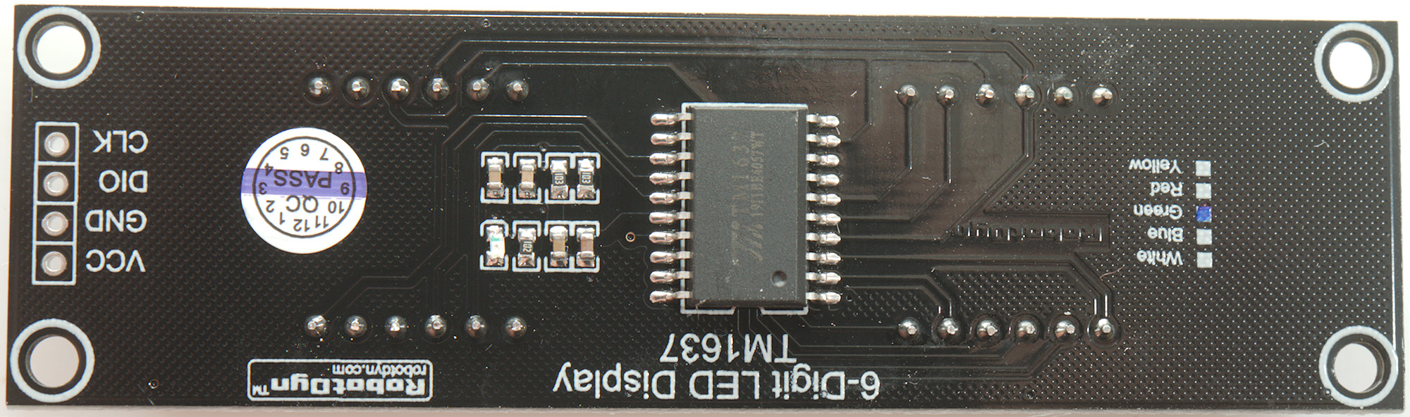
TM1637 6 digit RobotDyn
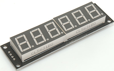
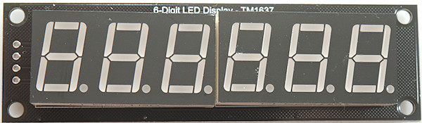
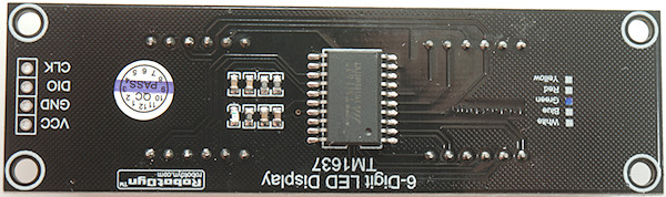
Connections: data=DIO, clock=CLK
Display type: _TM1637_6DX_
This display do not have the digits in sequence, the driver has a table to fix it. This makes it a regular 6 digit display that exist in 5 different colors and with the TM1637 chip it only needs two connections.
Aliexpress search
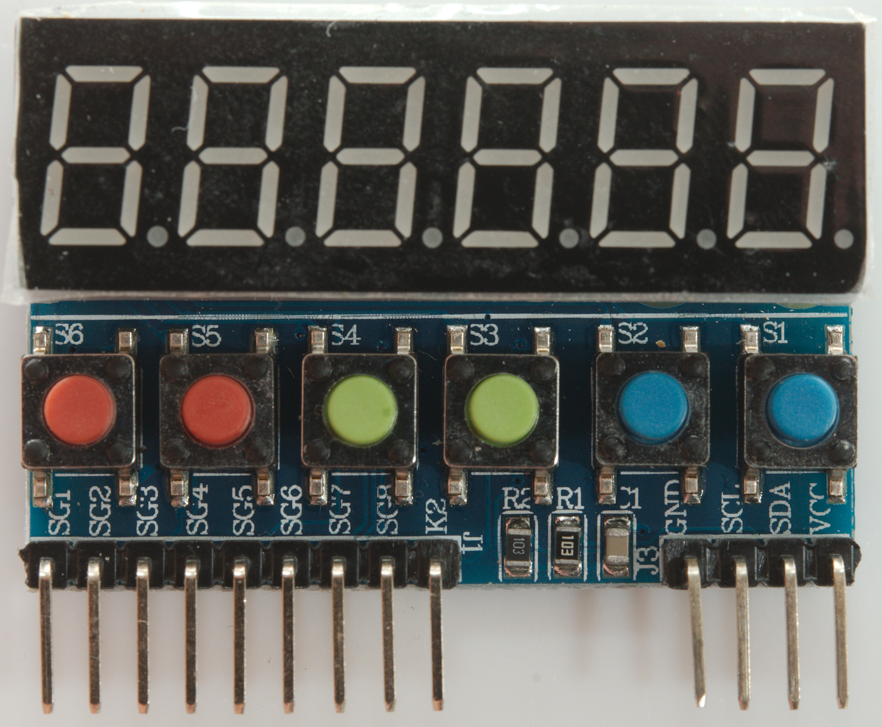
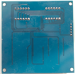
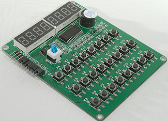
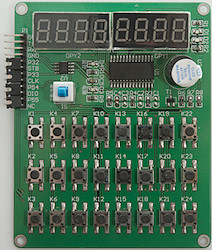
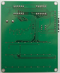
TM1637 6 digit, 6+ keys
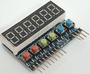
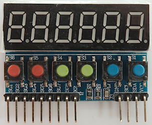
Connections: data=SDA, clock=SCL
Display type: _TM1637_
These displays only needs two connections. In addition to the 6 buttons on the circuit board it supports 8 external buttons. Only one button can be pressed at a time.
The keys are defined as KEY_S1 to KEY_S6 and can be read with readKeyIndex or readKeyIndexOnce.
Use Keys are read with readKeys to get a bitmask of pressed keys.
The marking on the circuit board is wrong, this is the way to connect the eight extra buttons. There are no definitions for the external keys, but they are numbered from 8 to 16.
Ebay search
TM1638 4 digit

Connections: data=DIO, clock=CLK, load=STB
Display type: _TM1638_
A simple four digit display using a fairly advanced controller with brightness adjustment.
Ebay Search
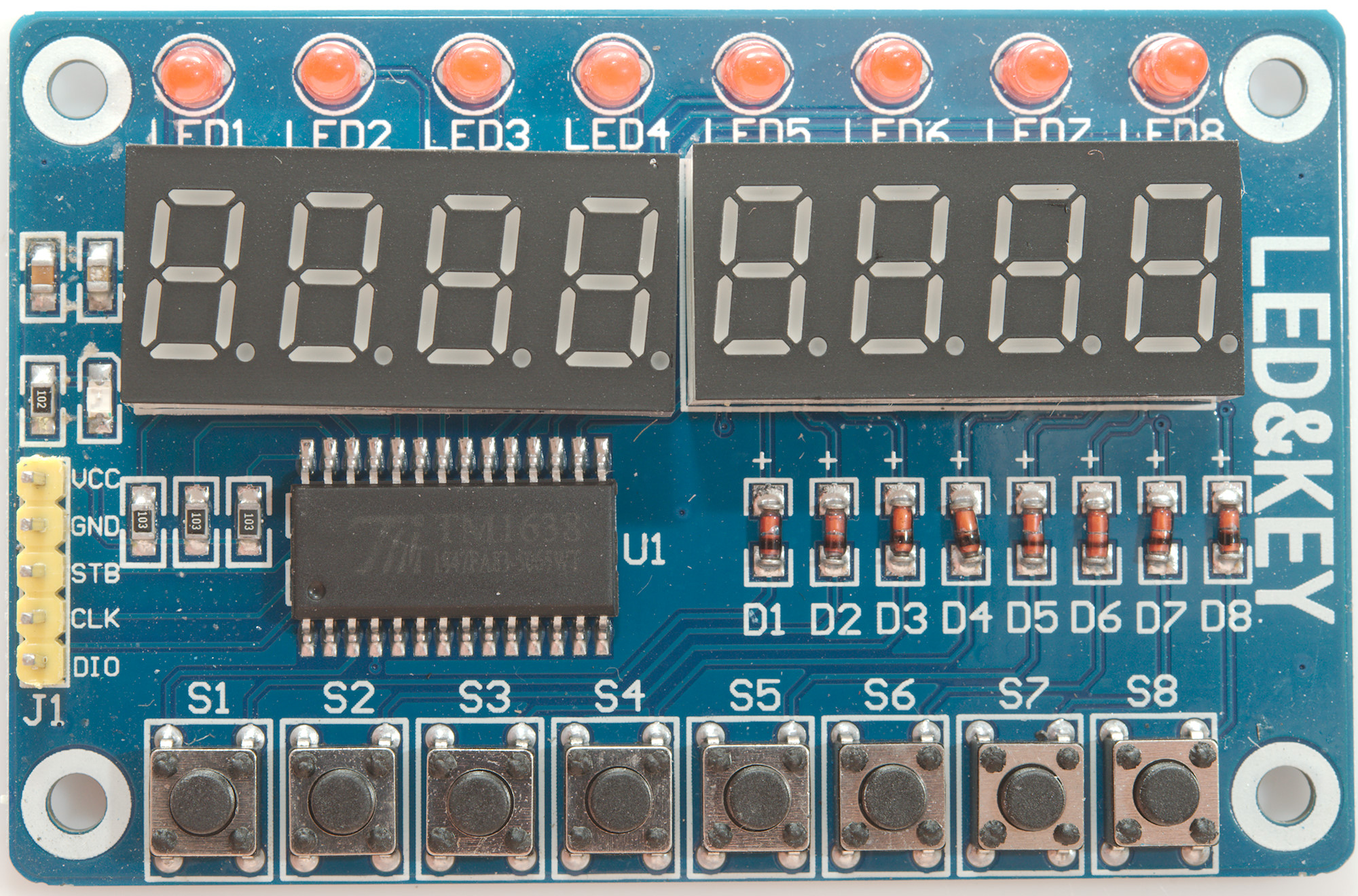
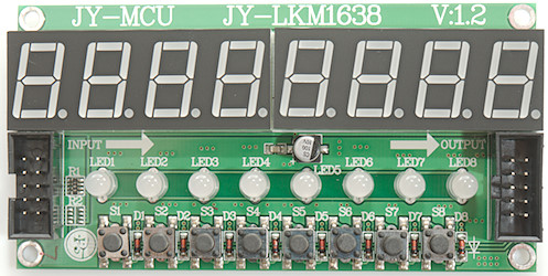
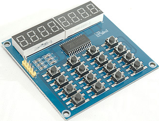
TM1638 8 digit, 8 indicators, 8 keys

Connections: data=DIO, clock=CLK, load=STB
Display type: _TM1638_
This board has 8 digit, 8 leds and 8 switches, this is not everything the chip supports, the software is made to support the full ability of the TM1638 chip.
The leds can be controlled with setIndicators and are defined as LED_1 to LED_8
The keys are defined as KEY_S1 to KEY_S8 and can be read with readKeyIndex or readKeyIndexOnce.
Ebay search Aliexpress search
TM1638 8 digit, 16 indicators, 8 keys
Connections: data=DIO, clock=CLK, load=STB0
Display type: _TM1638_
This board has 8 digit, 8 dual color leds (Red and Green) and 8 switches, this is not everything the chip supports, the software is made to support the full ability of the TM1638 chip.
Due to the connectors the display cannot be mounted behind a front panel.
The leds can be controlled with setIndicators and are defined as LED_1R, LED_1G, LED2R, LED_2G to LED_8R, LED_8G This driver also has definitions without R or G in the name, they match the G definitions.
The keys are defined as KEY_S1 to KEY_S8 and can be read with readKeyIndex or readKeyIndexOnce.
It is possible to chain multiple displays, this is done by using different STB/load pins for each display, the pins in the connectors are routed for this. The driver do not directly support multiple displays with different load pins, but it is easy enough to handle by using multiple instances:
Code:
LEDDisplayDriver display0(DIOpin, CLKpin, STB0pin, true, 8);
LEDDisplayDriver display1(DIOpin, CLKpin, STB1pin, true, 8);
LEDDisplayDriver display2(DIOpin, CLKpin, STB2pin, true, 8);
LEDDisplayDriver display3(DIOpin, CLKpin, STB3pin, true, 8);
LEDDisplayDriver display4(DIOpin, CLKpin, STB4pin, true, 8);
LEDDisplayDriver display5(DIOpin, CLKpin, STB5pin, true, 8);
Then the different instances of LEDDisplayDriver will handle the different displays.
Ebay search
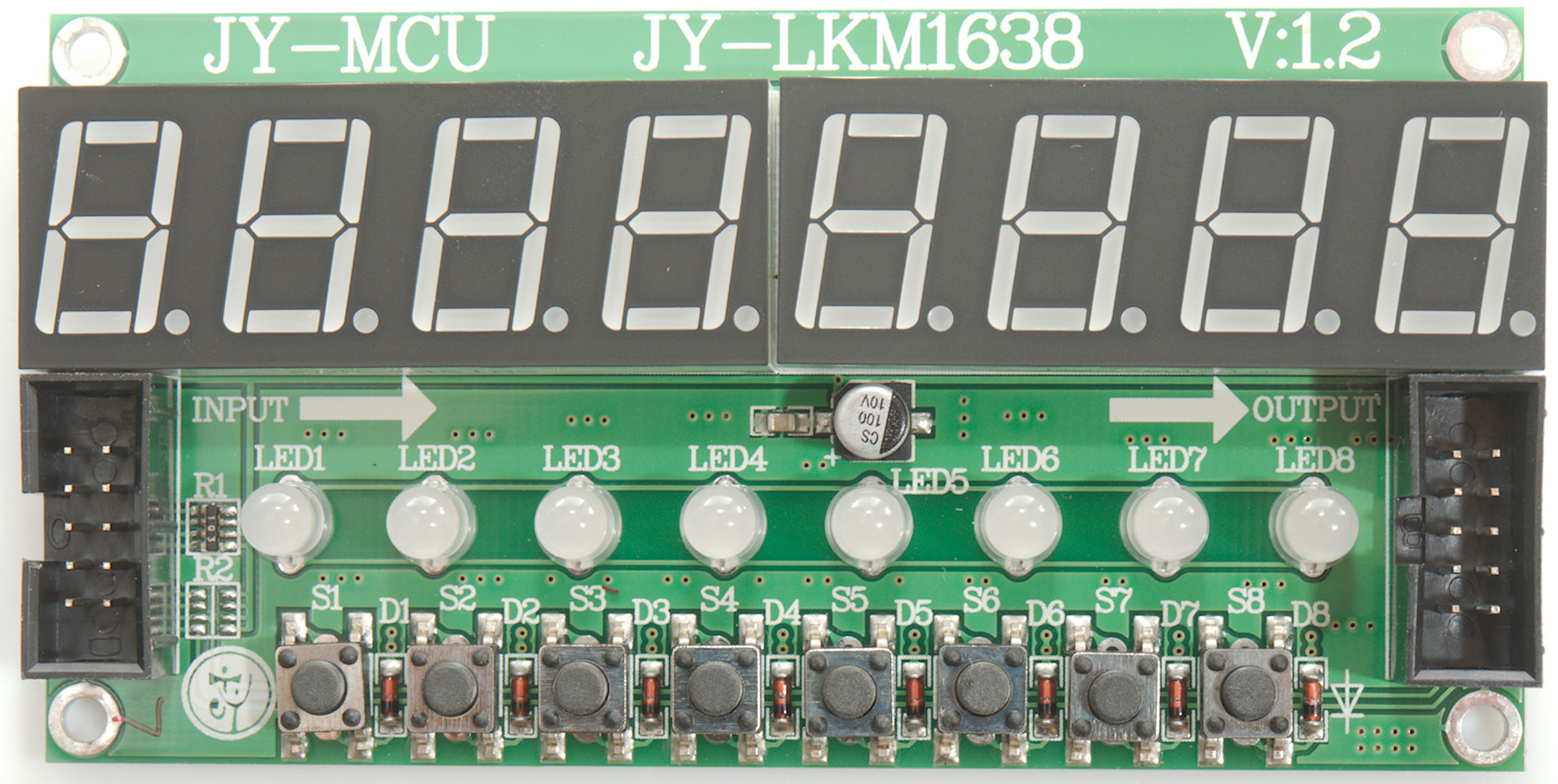
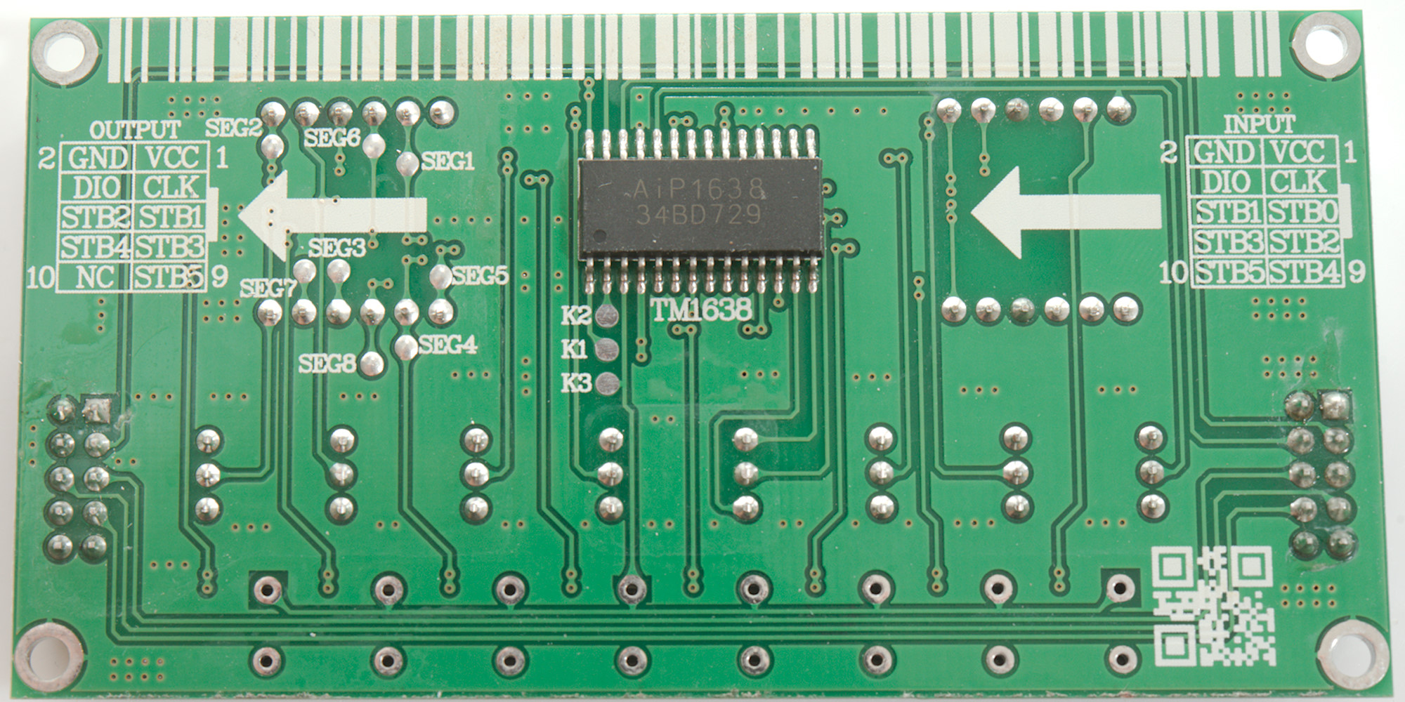
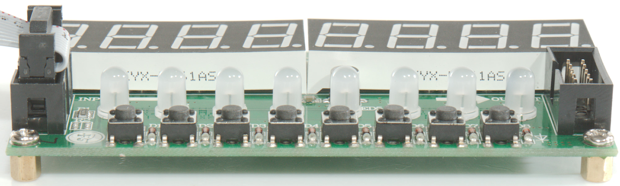
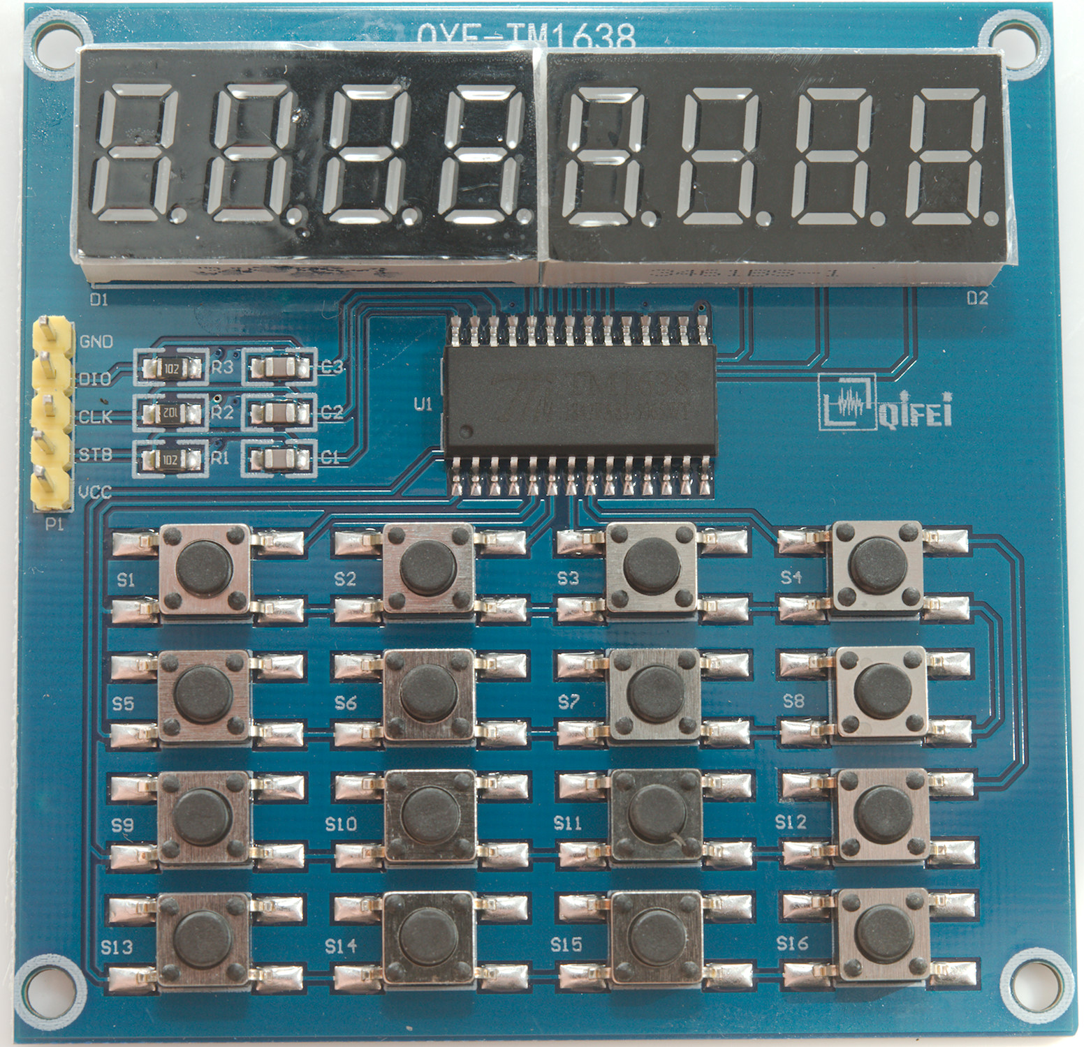
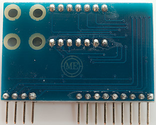
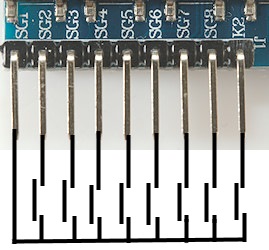
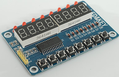
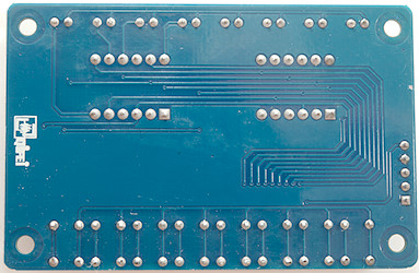
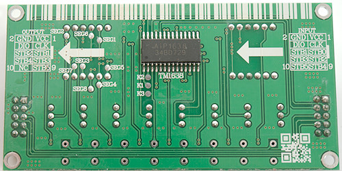
TM1638 8 digit, 16 keys
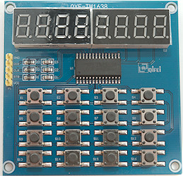
Connections: data=DIO, clock=CLK, load=STB
Display type: _TM1638_QYF_
This board has 8 digit and 16 switches, the segments and digits pins are swapped. This driver is not a full TM1638 driver, but only supports this board (The indicators are not implemented).
The keys are defined as KEY_S1 to KEY_S16 and can be read with readKeyIndex or readKeyIndexOnce.
Ebay search Aliexpress search
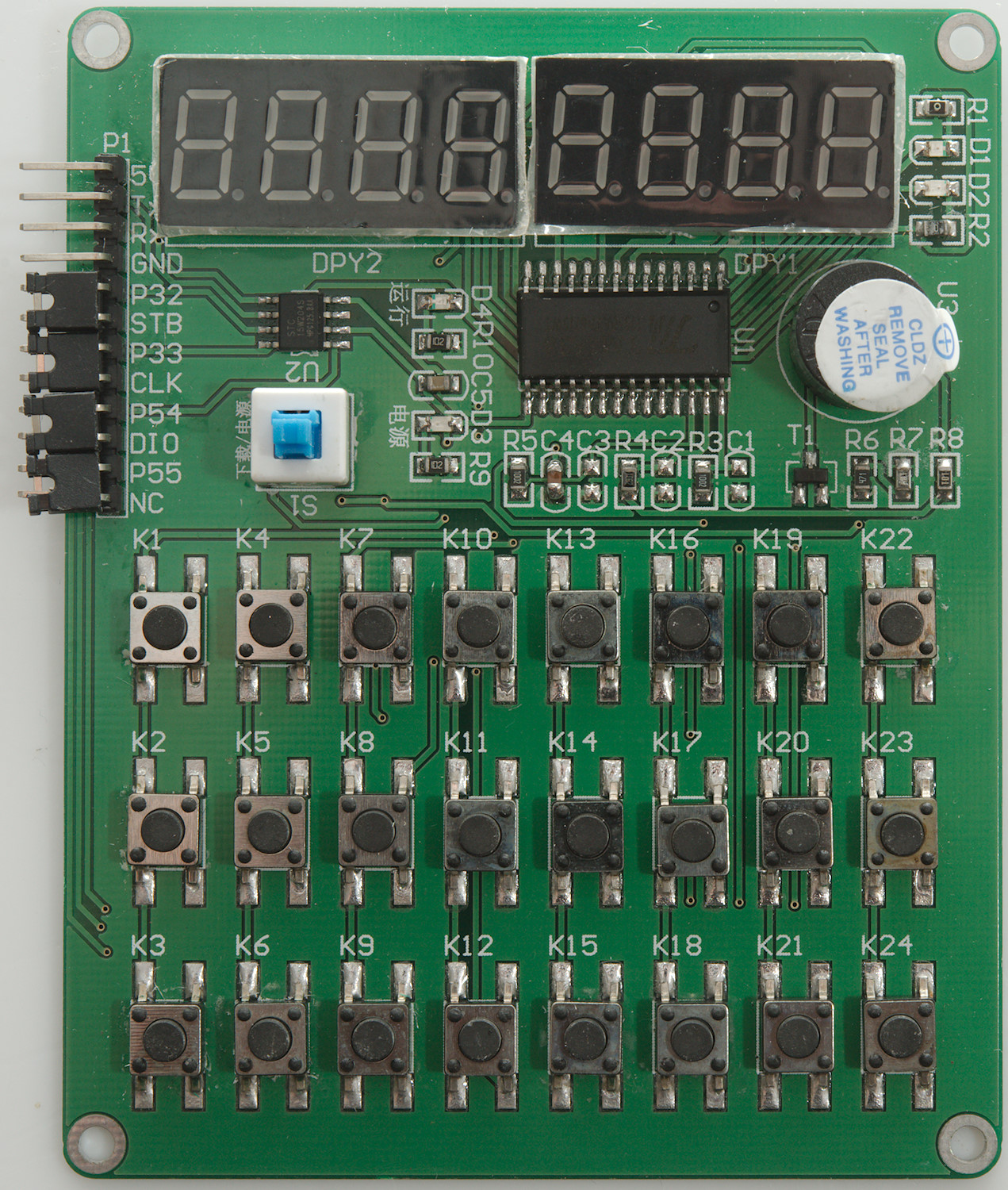
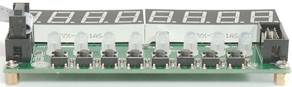
TM1638 8 digit, 2 indicators, 24 keys
Connections: data=DIO, clock=CLK, load=STB, this means removing the jumpers.
A 1kOhm pullup to 5V must be added to the DIO line for the keyboard to work and the switch S1 must be pushed down for anything to work.
Display type: _TM1638_HWA11_
This board has 8 digits, 24 switches and 2 indicators, it do also has a buzzer, but it is not supported through the TM1638.
The driver for this display is the same as for _TM1638_ except the LSB/MSB digits are swapped on the display.
The keys are defined as KEY_K1 to KEY_K24 and can be read with readKeyIndex or readKeyIndexOnce.
The two led can be controlled with setIndicators and are defined as LED_1 and LED_2
Ebay search
The software
The simple usage
Before the library can be used the LEDDisplayDriver.h must be edited to match the used display. Either put the LEDDisplayDriver.h & LEDDisplayDriver.cpp files in your protect directory or you have to go to the Arduino libraries/LEDDisplayDriver folder and change it.
Enable the desired display define (Only one must be enabled) and adjust number of digits.
Some examples on using the library.
Creating the display object is fairly standard, with only a minimum of parameters:
Code:
LEDDisplayDriver display(data,clock);// 4 digit mode with 2 connections to display
LEDDisplayDriver display(data,clock,load);// 4 digit mode with 3 connections to display
Show a number


Code:
display.showNum(123);
display.showNum(17.5);
This is, of course, the simplest usage where the number will use all the digits.
Using it for a clock display


Code:
LEDDisplayDriver display(data,clock,false,4);// Turn auto update off, this is never required, but makes the code a bit faster

display.setDp(1);// The colon is on digit 1, this will turn it on independent of the show functions called.
display.showNum2Left(hour);// I could also have used the full call: display.showNum(hour,0,2);
display.showNum2Right(minutes)// I could also have used the full call: display.showNum(minutes,2,2);
display.update();// Transfer the above 3 calls to the display
In this example the display is updated in two sections and the forced decimal point is used to turn the colon on. To get best performance auto update is disables and a manual call to update is used.
Controlling segments directly


Code:
LEDDisplayDriver display(data,clock);

byte data[]={digitD,digit0,digitN,digitE};
display.showDigits(data,0,4);
It could also be done this way, it is more useful when combining a number with a status segment:
Code:
LEDDisplayDriver display(data,clock,false,4);// Turn auto update off, I want to call multiple show before updating display

display.showDigit(digitD,0);
display.showDigit(digit0,1);
display.showDigit(digitN,2);
display.showDigit(digitE,3);
display.update();
A temperature display


Code:
LEDDisplayDriver display(data,clock,false,4);// Turn auto update off, I want to call multiple show before updating display

display.showNum1decimal(24.3,0,3);
display.showDigit(digitDeg,3);
display.update();
This routine uses a floating point routine to display a number with 1 decimal and shows a ° character after the temperature.
Displaying text


Code:
LEDDisplayDriver display(data,clock,true,8);// Use a 8 digit display

display.showText("Hello");
Optimizing library for the applications: #define
There is a couple of #define in the header file to control how the library is build.
Display type select
At the start of the .h file is a list of defines to select display type, see the section with pictures of different display, this shows exactly what define to select and how to connect the data wires.
Some displays requires interrupts, the following defines makes a macro to call the interrupt handler and adds code to initialize a timer. For this to work "DISPLAY_INTR(display)" must be included in your program. It is not required to use this interrupt code, it is possible to call the display interrupt handle from you own interrupt routine ("display.updateIntr()"), this is required on non-MEGA processors.
- _USE_TIMER1_: Use interrupt 1, this is valid on Mega328, Mega2560 and Mega32U4
- _USE_TIMER2_: Use interrupt 2, this is valid on Mega328 and Mega2560
- _USE_TIMER3_: Use interrupt 3, this is valid on Mega2560 and Mega32U4
- _USE_TIMER4_: Use interrupt 3, this is valid on Mega2560 and Mega32U4, this may require a call to "begin()" to get the 1kHz update rate.
- _USE_TIMER5_: Use interrupt 3, this is valid on Mega2560
DELAY_TIME
This controls the delay between clock and data changes on the communication lines, low value will make it fast (i.e. 1 or 0), high value (i.e. 10) will make it slower and less susceptible for noise and long wires.
_FAST_CLOCK_
When defined the library will use direct IO, this is faster than Arduino standard functions, but not compatible with all processor types. The direct IO will also use a few bytes more memory. Using direct IO with DELAY_TIME 0 will make the display update very fast!
_ENABLE_6_DIGITS_
When defined the library supports long, this is only needed for 5 or more digit displays. For displaying float/double on 5 digit displays long is required.
As standard it is included, but some memory may be saved on displays with 4 or less digits by commenting this #define
_INCLUDE_BYTE_
Include a byte version of show, this is slightly faster than the standard int version.
As standard it is included, but some memory may be saved by commenting this #define, then byte will be handled by the int routines.
_INCLUDE_SCROLLING_TEXT_
Include the routines to show scrolling text and the speed setting for it. Excluding this will save two bytes of ram and a few bytes of flash.
MAX_DIGITS
Define the frame buffer size, default is 8, but when chaining multiple displays more space is needed. Displays with more than 8 digits may automatic increase this value.
1 byte of ram is used for each digit with 7 segment displays, 14 segment use 2 bytes and 16 segment may use 2 or 4 bytes for each digit.
Constants
These are values defined and used internal in the library, they may also be useful in some programs.
MAX_BRIGHTNESS
For display with brightness control this will show the highest possible brightness value, usual 7 or 15. Using higher values will be limited to this value.
For displays without brightness control this value is 0
DIGIT_TYPE
Type definition for a single digit, this type must hold all segments and is the type used in the showDigit(), showDigits() and getDigits() calls.
For 7 segments display it will be byte.
SEGMENTS_7
The library is originally build for 7-segments displays and this constant will be defined when using them. This will usual means DIGIT_TYPE is byte.
SEGMENTS_14
When using 14-segment displays this constant is defined, this means the DIGIT_TYPE is uint16_t, i.e. a 16 bit data type.
SEGMENTS_16
For 16-segments display this constant is defined. These displays will use either uint16_t or uint32_t for DIGIT_TYPE, the last is required to keep track of a decimal point.
_USE_INDICATOR_ and INDICATOR_TYPE
The _USE_INDICATOR_ is defined for displays with indicators and the The INDICATOR_TYPE is the data type to hold the the indicators. It must be able to hold all indicators in one bitmask. It is used in showIndicators() and getIndicators()
_KEYS_ and KEY_TYPE
The _KEYS_ is defined for displays with supported keys. The KEY_TYPE is the type to hold a bitmask of pressed keys, it is used by readKeys();
DISPLAY_INTR
A macro to call the display updateIntr() routine for displays that requires interrupt, empty for other display types.
Other
Displays with indicators or keys will usually define constants for them, see the chapter about the display for the names.
Character constants for 7 segments displays
The library has some useful constants for handling the display.
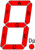
First there is all the segment bit masks: SEG_A, SEG_B, SEG_C, SEG_D, SEG_E, SEG_F, SEG_G and SEG_DP
They are defined with #define and the definition will change change depending on selected display type. A on segment is always a 1 bit, any needed inversion for this is done by the library.
I have tried to make the characters as legible as possible (Some are hopeless like KMVWXZ), this means mostly ignoring upper/lower case and most symbols are empty.
Symbols and numbers (0x20..0x3f)


Constants: digitQuote2, digitQuote1, digitOpen, digitClose, digitDp, digitMinus


Constants: digit0..digit9, digitEqual
The numbers and A-F also available as an array: segmentPatterns[] that can be indexed with 0 to 15.
Upper case letters (0x40..0x5f)


Constants: digitA..digitO


Constants: digitP..digitZ, digitOpen, digitBackslash, digitClose, digitUnderscore
Lower case letters (0x60..0x7f)
There is only a few letters that are different.


Constants: digita..digito

Constants: digitp..digitz, digitOpen, digitVerticalslash, digitClose
Other symbols
Some symbols that is not within the 96 ascii characters


Constants: digitEmpty, digitDp, digitTop, digitBottom, digitRight, digitLeft, digitDeg, digitAll
Character constants for 14 segments displays
The names are exactly the same.

The letters for the segments are not standardised for 14 segments displays, each brand uses there own scheme. I also did my own scheme, I wanted single letter names and to avoid similar letters.
Symbols and numbers (0x20..0x3f) 14 segments


Constants: digitQuote2, digitQuote1, digitOpen, digitClose, digitAsterix, digitPlus, digitDp, digitMinus, digitSlash


Constants: digit0..digit9, digitLT, digitEqual, digitGT
The numbers and A-F also available as an array: segmentPatterns[] that can be indexed with 0 to 15.
Upper case letters (0x40..0x5f) 14 segments


Constants: digitA..digitO


Constants: digitP..digitZ, digitOpen, digitBackslash, digitClose, digitUnderscore
Lower case letters (0x60..0x7f) 14 segments
Most lower case letters are different from the upper case version, but not all.


Constants: digita..digito


Constants: digitp..digitz, digitOpen, digitVerticalslash, digitClose
Other symbols 14 segments
Some symbols that is not within the 96 ascii characters


Constants: digitEmpty, digitDp, digitTop, digitBottom, digitRight, digitLeft, digitDeg, digitAll
Character constants for 16 segments displays
The names are exactly the same as for 7 and 14 segments displays. The symbols are very similar to 14 segment display, but some lower case letters are better.
The DP segment is defined, but it will usually not work, even if it is present on the display, because most drivers can only handle 16 segment and it is segment #17. Some display may have a driver that can use other Arduino pins to control the DP segment.
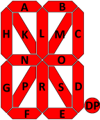
The letters for the segments are not standardised for 16 segments displays, each brand uses there own scheme. I also did my own scheme, I wanted single letter names and to avoid similar letters.
Symbols and numbers (0x20..0x3f) 16 segments


Constants: digitQuote2, digitQuote1, digitOpen, digitClose, digitAsterix, digitPlus, digitDp, digitMinus, digitSlash


Constants: digit0..digit9, digitLT, digitEqual, digitGT
The numbers and A-F also available as an array: segmentPatterns[] that can be indexed with 0 to 15.
Upper case letters (0x40..0x5f) 16 segments


Constants: digitA..digitO


Constants: digitP..digitZ, digitOpen, digitBackslash, digitClose, digitUnderscore
Lower case letters (0x60..0x7f) 16 segments
Most lower case letters are different from the upper case version, but not all.


Constants: digita..digito


Constants: digitp..digitz, digitOpen, digitVerticalslash, digitClose
Other symbols 16 segments
Some symbols that is not within the 96 ascii characters


Constants: digitEmpty, digitDp, digitTop, digitBottom, digitRight, digitLeft, digitDeg, digitAll
All functions
General notes
The parameters first,count is nearly always optional, when present it specify the first digit and the number of digits to use. The first digit is the leftmost digit and is number 0, count must be 1 to use exactly one digit and 4 to use exactly 4 digits.
Digit number: 
The specified digits will always be cleared and depending on what to display and display format they may be filled again.
When leaving out the first,count parameter most routines will use the full display width, exceptions are the ...left, ...center, ...right routines and some single digit functions.
Constructors
The constructor can be used two ways:
Code:
LCDDisplayDriver display(data,clock);
LCDDisplayDriver display(data,clock,load);
LCDDisplayDriver display(data,clock,autoUpdate,digits);
LCDDisplayDriver display(data,clock,load,autoUpdate,digits);
The first two lines will create a object for a 4 digit display with autoUpdate, the 3 & 4 lines makes it possible to specific autoUpdate and change number of digits. When using more than 8 digits, remember to change the define "MAX_DIGITS". For displays that requires 3 control lines the versions without "load" parameter is not available. A display with two control lines can always be created with 3 control lines, the load parameter is ignored.
Specifying more digits than there is space for in the frame buffer may give some strange compilation errors!
Bytes and integers
Code:
showNum(number);
showNum(number,first,count);
This will show an integer, depending on defines it will be locked to int type or select between byte, int and long. Numbers are right adjusted within the available space.
These routines support negative numbers, if there are space on the display.
Code:
showNum(number,true);
showNum(number,first,count,true);
Same as above, but with leading zeros, this will not work with negative numbers. The minus takes precedence over the zeros.
Code:
showNum2Left(number);
showNum2Center(number);
showNum2Right(number);
showNum2LeftLZ(number);
showNum2CenterLZ(number);
showNum2RightLZ(number);
Show two digit on either the left, center or right part of the display, these function are for bytes, i.e. unsigned numbers. The LZ version will include a leading zero.
Code:
showNum4Left(number);
showNum4Right(number);
showNum4LeftLZ(number);
showNum4RightLZ(number);
Show four digit on either the left or right part of the display, these function are mostly useful for 6 or more digit displays. The LZ version will include leading zero.
Code:
showNumWithPoint(number,pointPosition);
showNumWithPoint(number,pointPosition,first,count);
Will show an integer number, but include a point on the display at the specified position. The point is specified from the right digit and leading zeros will be added as needed:
showNumWithPoint(1000,0) will show 1000.
showNumWithPoint(1000,1) will show 100.0
showNumWithPoint(1000,2) will show 10.00
showNumWithPoint(1,2) will show 0.01
Code:
showNumWithPrefix(prefix,number,pointPosition);
showNumWithPrefix(prefix,number,pointPosition,first,count);
Same as point routines, but first digit is reserved for status information, except it will be used for sign and point when required:
showNumWithPrefix(digitBottom,100,1) will show _10.0
I.e. prefix specifies what segments to turn on at the leading digit.
Bytes and integers in hex (BCD)
Code:
showHex(number);
showHex(number,first,count);
Show a hex number on the display, hex numbers always includes leading zeros. BCD can be display with the hex functions, it is exactly the same, but only uses 0-9.
Code:
showHex2Left(number);
showHex2Center(number);
showHex2Right(number);
Shortcuts to place two hex digits on a display.
Code:
showHex4Left(number);
showHex4Right(number);
Shortcuts to place four hex digits on a display.
Bytes and integers in binary
Code:
showBin(number);
showBin(number,format);
showBin(number,format,first,count);
Show a binary number in the display, it has a couple of different formats, some of them will pack two bits in each digit:
- format=0: Use normal number digits: (This format is used for showBin(number))
or or
- format=1: Use small digits:
 or
or 
 or
or 

- format=2: Use small digits in the upper part of the segments:

 or
or 
 or
or 

- format=3: Pack two digits in each segment and only show ones:

 or
or 

 or
or 


- format=4: Use the upper segments:

 or
or 

 or
or 


- format=5: Use both segments:


 or
or 

 or
or 


Showing in binary can be used to show input ports or settings. Using format 3 or 4 is very compact and do not look like numbers or letters.
Float and double (They are the same on a MEGA)
Code:
showNum(number);
showNum(number,first,count);
The same routines as for integers, but this time a point will be used depending on the number. It can show from 0.001 to 9999. on a four digit display, it supports negative numbers, but that will be one numeric digit less, i.e. -0.01 to -999., overflow will be shows as ----.
Code:
showNumWithPrefix(prefix,number);
showNumWithPrefix(prefix,number,first,count);
This reserve one digit for status usage (called prefix), but do not limit the floating display to only 3 digit, the point and sign is shown on the status digit.
This means: .001 to 999 and -.001 to -999 can be displayed.
On the status digit it is best not to use the point and minus segments and avoid patterns that can look like a number.
Code:
showNum1decimal(number);
showNum1decimal(number,first,count);
showNum2decimals(number);
showNum2decimals(number,first,count);
showNum3decimals(number);
showNum3decimals(number,first,count);
Showing float with fixed decimal location is fairly simple, these routines uses "showNumWithPoint" and simply multiplies the number with 10/100/1000 and rounds correctly.
See also showNumWithPoint() in the "Bytes and integers" section.
Text, strings and characters
Characters are available as digit... constants, but they can also be displayed directly with these routines.
Code:
showChar(digit,character);
showText(string)
showText(string,first,count)
showText(character_array)
showText(character_array,first,count)
The showChar() is for a single character at specified position, the showText will work with either a String or a char[] type. The actual text length do not affect the display, with short strings it will be filled with blanks and with long strings only the first characters will be shown.
Code:
showTextScroll(string)
showTextScroll(string,first,count)
showTextScroll(character_array)
showTextScroll(character_array,first,count)
setScrollSpeed(delay);
With these routines is is possible to show longer text than fits on the display, they will scroll with the specified delay between each step. The first display width of text will be shown without any delay, but there will be a character delay before returning.
The setScollSpeed define the delay between each update, default is 300.
Hint: To make text scroll in from the right, start the string with numberOfDigits-1 spaces.
The Mega processors do not have much RAM memory, to conserve RAM memory it is often a good idea to use:
Code:
display.showTextScroll(F("My text"));
This will only copy the text to RAM when it is displayed and then release the RAM again.
Indicator segments
Some displays has indicators, these are handled outside the standard show functions.
Code:
showIndicators(bitmask);
addIndicators(bitmask);
subIndicators(bitmask);
getIndicators();
This routine is only defined for displays that support indicators, there may also be defined some constants for the indicators. The add/sub routines will turn on/off specified indicators without affecting any other indicators.
The actual data type of the bitmask will depend on the number of indicators supported on the display.
Direct segment access
Code:
showDigit(digit,index);
showDigits(digits,first,count);
The first routine shows a byte with segment definitions on the specified digit, the second routines takes an array of bytes/uint16_t (Use DIGIT_TYPE, it contains the correct type) and show it on sequential digits. Use the "digit.." constants to get the values needed or build them with the SEG_x definitions. Do not write a binary or hex value, it will not be compatible with all display types.
Returns a pointer to the actual digit data, this makes it possible to manipulate the final result before displaying it. There is generally very little reason for using this function, raw digit access is better done with showDigit or showDigits. The returned pointer will always be valid, the internal data are not reallocated or moved.
It can be used like this:
*(display.getDigits() + 1) = digitEmpty;
or
*(display.getDigits() + 1)|= digitDp;
For this to work autoUpdate must be off and update called after the manipulations.
Key input
A few display types supports keys, there are some routines to read these. The library do not do any scanning or debouncing, it will only read the keys when called. The call must not be done from an interrupt routine, that will disrupt the display updates!
Code:
readKeys()
readKeyIndex()
readKeyIndexOnce()
The readKeys will return a bitmask of all the keys, it may be an byte, unsigned int or unsigned long with a 1 in the positions with keys pressed.
readKeyIndex will use readKeys, and return the index of a pressed key or 0 when no key is pressed.
With readKeyIndexOnce each key press will only be returned once, a working debounce can be implemented by waiting at least 10ms between calls to read the keys.
When only a single key is used at a time, the readKeyIndex and readKeyIndexOnce will work fine, the readKeys is for handling multiple simultaneous pressed keys (The hardware may have some limits on this).
For displays with keys there is usual defined constants for the keys, they are called "KEY_xx" where xx is the key name/number on the circuit board. The defined values match what is returned by readKeyIndex and readKeyIndexOnce.
Support routines
Code:
clear();
clear(digit);
numberOfDigits();
Clear the display, this is not necessary to call before any of the show functions, but may be useful for cleaning a status digit. This will clear digits and indicators, but will not affect the setDp() function.
numberOfDigits() will return the defined number of digits, i.e. the digits value used in the constructor.
Code:
update();
update(digit);
setAutoUpdate(false);
The setAutoUpdate can enable/disable the automatic updating after clear, setDp, setBrightness, setOn or show functions. This can also be defined in the constructor.
When automatic update is not enabled the update function must be called to update the full display, if only one digit is change the update(digit) can be used. When more than one digit is updated it is always recommended to use a "update()", not the single digit version.
Code:
setBrightness(value);
getBrightness();
setOn(true);
setDp(digit);
removeDp();
showTest();
begin();
The brightness can be adjusted from 0 to 7 or 15 depending on display type. The define MAX_BRIGHTNESS will be 0, 7 or 15 depending on supported brightness settings. The setBrightness routine will limit higher values to MAX_BRIGHTNESS. To check actual brightness use getBrightess().
The setOn can turn the display on or off. The setDp will add a decimal point or colon on the display, this is controlled outside the show functions and will stay on until removeDp is called or setDp is called with a invalid digit. The library do not use this function for decimal points in numbers. The showTest will turn all segments and indicators on, calling other show functions will override this.
The Arduino programs most timers to slightly below 1kHz update rate (Except MegaU4 intr4), to get precisely 1kHz update rate place the display.begin() in the "void setup()" section.
Some display protocols gives a feedback during communication, the last feedback is stored in an internal variable and can be checked with this function. If this function is false, no feedback was received from the display and it is probably not connected or defective. Displays without feedback will always return true.
Print and LCD API
I do not like the LCD API for a 7 segment display, it is a very bad match for it, but some people want it. To solve this I have added a class called "LEDLCDAPIDriver", it is build on LEDDriverDisplay and Print, it exposes the LCD API.
Because this API is based on text, the LEDDriverDisplay library will include the code for text display, but no other show function.
The API from LEDDriverDisplay is hidden, to include both change the declaration of LEDLCDAPIDriver (Change private to public in the class line)
Constructors
Code:
LEDLCDAPIDriver display(data,clock);
LEDLCDAPIDriver display(data,clock,load);
LEDLCDAPIDriver display(data,clock,autoUpdate,digits);
LEDLCDAPIDriver display(data,clock,load,autoUpdate,digits);
The first two lines will create a object for a 4 digit display with autoUpdate, the 3 & 4 lines makes it possible to specific autoUpdate and change number of digits. When using more than 8 digits, remember to change the define "MAX_DIGITS". For displays that requires 3 control lines the versions without "load" parameter is not available. A display with two control lines can always be created with 3 control lines, the load parameter is ignored.
Specifying more digits than there is space for in the frame buffer may give some strange compilation errors!
LCD API
See here for official specifications
Code:
init();// Uses begin to initialize driver
print(value);// Print a value as characters
println(value);// Print a value as characters then move cursor to home
clear();// Clear the display
home();// Move cursor to home
setCursor(Row,Col);// Row is ignored
setBacklight(val);// Set brightness for LED display
on();// Turn LED display on
off();// Turn LED display off
keypad();// see "readKeyIndex()"
setScrollSpeed(delay);// See setScrollSpeed above.
When the end of the display is reached it will scroll sideways.
The , and . character will be moved to the point on the previous digit, if there is one.
Code:
update();// Update the display, default it is automatic
If the library is initialized with autoUpdate to false this function must be used after some print's.
How is the software designed
This is a short description on how the software is put together. Some very important point for me was low memory footprint and fast execution, for this reason I uses #define and #if to enable and disable code sections, depending on what is required for each display type. This is not the most elegant way to program, but it saved a lot of space in the processor.
Display selection and optimization (Header file)
At the top of the header file is a couple of defines to select the display type, each one will include code to handle that display. It is not possible to enable more than one at a time! These defines controls segment definitions, keyboard and indicator support, included driver.
Constant definition and feature setup (Header file)
This section will define constants depending on selected display, some of these constants are used later in the code for more generic definitions and some are constant for the user (max. brightness, indicators and key names)
Segments definition (Header file)
Not all display drivers has the segments at the same position, i.e. for one display the segment bits are ".ABCDEFG" when streaming out, for another they are "FGEDABC.". The actual definition is selected by the display type and will define a couple of "SEG_x" bitmasks for that display type. The drivers are designed to always require a 1 bit to turn that segment on, i.e. to turn segment A and B on, it will always work to write SEG_A|SEG_B.
This is then used to define constants with numbers, character and special symbols, they are all named digit.... Because they use the "SEG_x" definition they will always be correct when the "SEG_X" definitions are correct.
IO port handling (Header file)
Arduino makes it easy to toggle IO bits with digitalWrite(port,bit), but this function is rather slow. To allow for optional optimization I have defined my own set of IO routines called dataHigh, dataLow, clockHigh, clockLow,..., as standard they map directly to digitalWrite, but when enabling fast IO they change to direct port access. This optimization probably only works on the Mega processors, other processors may not work the same way for IO, but then they are usual much faster and the optimization is not as important there.
When using direct IO some more variables are required and RAM is allocated for that.
Class header (Header file)
The LEDDisplayDriver class has a lot of "show" routines for different formats and data types, many of them are just shorthand and maps to more general routines with more parameters.
There is also some optional mapping for data types. Byte can either be handled by a byte based routine or by a int based routine (_INCLUDE_BYTE_). On a 8 bit micro the byte will by faster and requires a simpler call, but when both bytes and int are used it means two display routines will be included. Disabling the byte routines means all bytes with be converted to int before being written to the display.
For a 4 digit display the maximum number to show is 9999, this is well below the 32767 maximum for int and there is no reason to support the long data type (_ENABLE_6_DIGITS_). This is especially true for float/double that always will use long when enabled.
Class header LCD API (Header file)
The LCD API is mostly a definition that maps directly to the LEDDisplayDriver, the only significant exception is the write function. This routine takes the output from the Print class, that does all the formatting.
The write function writes a character to the display and either moves the cursor to next position or if at the last position scrolls the display.
Interrupt handler/vector (Header file)
This section first classifies the different Arduino/Atmel processors into a few types (_uno_, _mega_ and _U4_), this is used in the definition of the interrupt vector and the initialization of the interrupt.
Next follows a definition of the interrupt vector depending on the selected timer and for timer 4 also the selected processor. This is empty when no interrupt is needed. The vector is defined as a macro that can be placed in the user program, this is necessary to get the instance of the driver. The only function of this vector is to call the updateIntr() function in the class. This function is independent of processor and could just as easily be called from a user defined interrupt routine on a non-mega processor.
Number and letter tables (cpp file)
To convert from a character to a segment pattern a table is needed, I have two tables:
One for 0-9 and A-F, this table is stored in RAM and can be used both from the driver and from the user (it is called segmentPatterns). It only needs to list the 16 character definitions in a array.
The next one is larger, it contains mapping for 112 ascii characters to segment patterns, this is stored in program memory and not directly accessible from the user program, but is used by showChar().
The class code (cpp file)
Next follows the code for the class, that is initialization and the different show... and other functions that needs some code, some of it is conditional, depending on options from the header file.
Timer and interrupt initialization (cpp file)
Here is code to initialize any (Except timer 0) of the possible timer interrupts on the Arduino, with check for supported processors. They all setup the timer to run at 1000Hz with either comparator or overflow interrupt. The Arduino will initialize some of its timers to run near this frequency after the class is instantiated, usual this is not very important because it do not fiddle with the interrupt settings. To always get the correct speed it is often necessary to add a call to "begin" in the setup routine, it will simple call this initialization again.
Display drivers (cpp file)
This is a fairly large section, but because only one section is enabled at a time it do not generate much code.
I have selected to do a separate implementation of each display type, this means some duplicated code when displays use the same chip, but it also means much simpler maintenance of the code. This is because I do only need to check the driver I change, not all the others. It also means I can write each driver more optimal for that display type, i.e. faster and more compact.
Each driver implements some routines to initialize the display, change setup and transfer data to the display and optionally a routine to read any keys.
There often are a couple of support routine to stream bytes, setup start and stop conditions, etc., these are added to the class header with defines in the private section. I.e. nearly each display driver has a corresponding section in the header file with function definitions.
Not working, what to look for
There is very little that can go wrong when using this library correctly. Here I have collect a list of stuff to check when it is not working.
- Check if correct display type is select in LEDDisplayDriver.h, use the chapter above about support displays to find the correct name.
- Display connected to the correct pins, use the chapter above about support displays to see the required connections.
- Program crashes immediately, this may be due to interrupt! Include the line "DISPLAY_INTR(display)" in your program, it will only generate code when needed.
- Refresh rate of digits is very slow or processor is slow. This may be wrong interrupt frequency for a interrupt controlled display. There can be two reason for this:
- Interrupt not correctly initialized, add "display.begin();" in "setup()"
- Some other library is using the same interrupt, change timer in LEDDisplayDriver.h (Just below display type selection).
- Display do not update, this may be because "autoUpdate" is disabled and there is no call to display.update();
- The last digits in a long display or multiple displays is strange or the program crashes sometimes, remember to change "MAX_DIGITS" in LEDDisplayDriver.h when using more than 8 digits.
Compatibility between displays
The library makes it easy to switch between different display, but there are a few limitations.
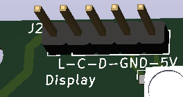
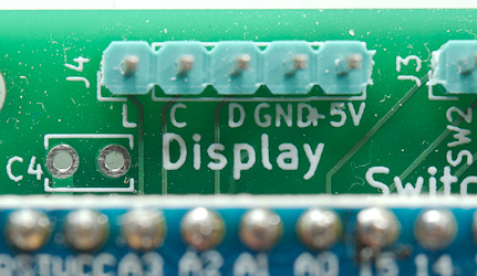
For the hardware I usually places a 5 pin pin header on the circuit board with Load, Clock, Data, GND and 5V connections, but I also have to be sure there is enough 5V current available, this can be an issue when using the 5V regulator on the Arduino and feeding it from a higher voltage.
Not all display needs to use the Load connection, but as long as I have spare pins on the Arduino I prefer to include it.
When doing the software I have to decide the number of digits, usual 4, 6 or 8, but other numbers are possible. The numbers on the digits will be compatible between all displays, but the decimal point is not supported on all displays, especially some 4 digit ones are missing it because they are designed for a clock display.
Indicators are usual unique to each display, except for a colon. This can be controlled with display.setIndicators(colonOn?COLON_DISP_0:0). On some displays it is connected to a decimal point segment, but using the correct display type will move it to the indicators domain.
My favorites and dislikes
Playing with all these display I found some I really likes and some I definitely did not like.
Favorites
HT1621 6 digit LCD: Very clear LCD display with the background light and fairly low power consumption, it have mounting holes.
This display has large digits, it includes mounting holes (but they are small) and they can be placed next to each other for longer display. It is possible to use both colon and decimal point on this display.
HS595 static: Completely static display and multiple modules of different sizes can be connected, there is mounting holes. Only dislike is that there must be some spacing between modules, it is not possible to make a 5+ digit display.
MAX7219: I like to have 8 digits and it is possible to adjust the brightness, the displays are a bit small. The module has mounting holes.
TM1637 4 digit: These are nice display, but you really have to search if you want a version with decimal point instead of colon. Just because both is present on the display, do not mean they are both supported. It has brightness adjustment and mounting holes.
A 6 digit display with fairly large digits, it exist in 5 different LED colors.
Dislikes
HC164: This display flickers while updating it and requires interrupt.
HC595: These displays requires interrupt and often the segment current is not controlled.
HT1621 12 digit LCD: It has no background light and all the indicators are Chinese words.
TM1638 24 keys: I do not like that it requires a 1kOhm pull-up. The display on/off switch is a bit silly and the buzzer do not work. I did not see any documentation on the communication protocol for the microprocessor.
Conclusion
If I can spare 3 pins on a Arduino processor it is basically possible to use any display with it, with a very small software change (un/comment some #define), at least if the number of digits are the same. It will also work if the display has more digits, but I would probably want do redo the display layout then.
If I want more than one display on a Arduino I can either use a display type that supports multiple displays or instantiate multiple copies of the driver and have displays on different pins.
I have added a lot of shorthand routines, they do not take up any extra space in the Arduino and make it a bit easier to use the display.
Notes and download
Over time I will probably add more displays to this library. If manufacturer or dealers would like me to support a display I will probably do it if they give me one or two displays of that type. The library is for displays with a 2 or 3 wire interface, do not ask about support for displays that needs more wires.
My email is "info" at my domain "lygte-info.dk"
Version: 1.01: Fixed serious bug in showChar (Oops) and added LCD API.
Version: 1.02: Add support for timer1 to 5 on the Mega2560, marked most of LEDLCDAPIDriver inline and change the init function.
Version: 1.03: Added support for 4 digit HT16K33 display with both colon an point. Both HT16K33 drivers now support multiple displays.
Version: 1.04: Added support for a large 4 digit HT16K33 display. Added a TM1637_COLON driver for compatibility reasons.
Version: 1.05: Added support for 8 digit HC595, it is added to the current HC595 driver. I also added some 1.8" single digit HC595+driver (HC595A_STATIC, driver inverts signal) displays.
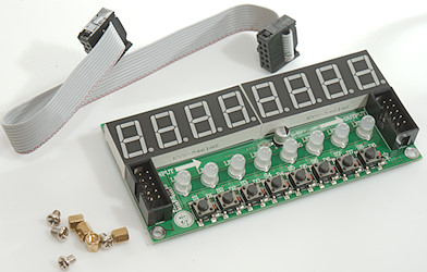
Version: 1.06: Another TM1638 display verified (JY-LKM1638) and a few constants added for it.
Version: 1.07: A MAX7219 with 0.56" digits, a single digit HC595 static and two HC595 with interrupts. Added scrolling text and done some preparation for displays with more than 7 segments.
Version: 1.08: Added 8 digit 14 segment display, added links to the displays on Ebay/Aliexpress
Version: 1.09: Added support for Arduino Nano Every (Mega4809) timer interrupts
Version: 1.10: Added 4 digit 14 segment display and verified a red MAX7219 module.
Version: 1.11: Added 6 digit TM1637 Robotdyn module
Version: 1.12: Added 6 digit 14 segment DIY display modules. Added addIndicators()/subIndicators() functions to make it easier to modify indicators.
Version: 1.13: Added 4 digit 16 segment DIY display module. Fixed rounding error when displaying negative float numbers.
Version: 1.14: Added 4 digit 7 segment 0.8" DIY display module.
Version: 1.15: Added 6 digit 7 segment 0.56" DIY display module, fixed bug with multiple display on _HT16K33_14SEG_4D_ and added getBrightess();
Version: 1.16: Fixed a bug with _HT16K33_4D_ (Code would not compile)
Version: 1.17: Added Sparkfun QWIIC SPX-16xxx 14 segment displays
Version: 1.18: Fixed _HT16K33_14SEG_4D_ and showTextScroll will not fail if count is larger than text length.
Download as library This includes examples and highlights of keywords
Download as sketch This is a skeleton project with the driver included, this is the best way to use the library.