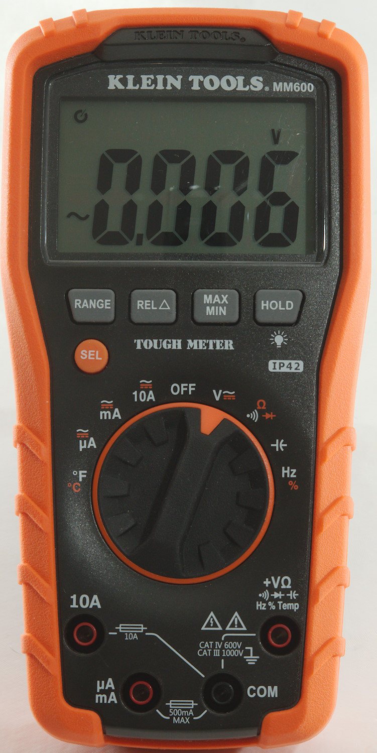
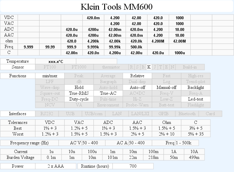
DMM Klein Tools MM600
Klein Tools say their meters are robust. I am not going to test that, but it feels that way.
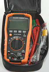
I got this meter without a box, but in the holster.
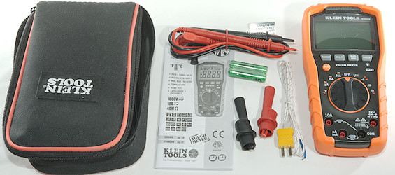
It contained the meter, the holster, probes, alligator clips, thermocoupler, batteries and a manual (This manual can also be downloaded). It was missing an adapter for the termocoupler, it is supposed to be there.
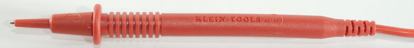
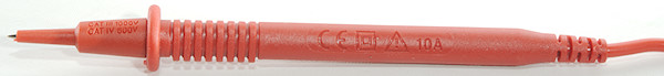
The standard probes are normal sizes and rated for 10A
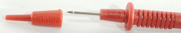
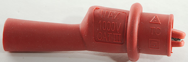
And CAT II 1000V or CAT III 1000V/CAT IV 600V depending on the tip covers.
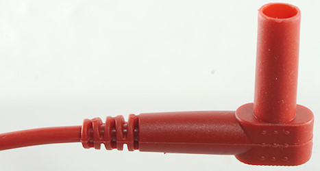
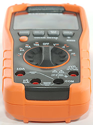
The plugs are fully shrouded and standard probe size.
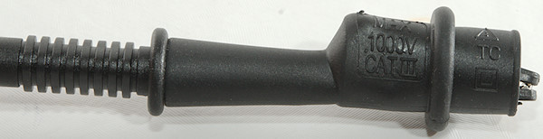
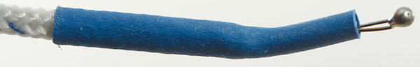
The alligator clips can be mounted when the tip covers are removed and gives CAT III 1000V protection.
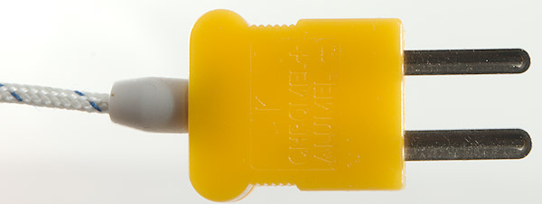
The thermoprobe has a standard thermocoupler connector and requires an adapter in the multimeter.
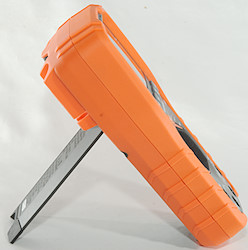
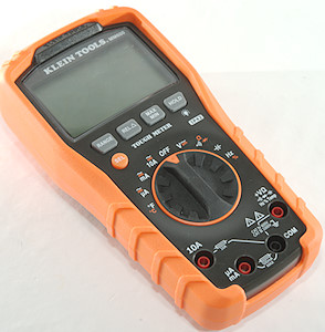
The range switch is rubberized and a bit hard to turn, but the heavy meter with the rubber cover can keep the meter is place for single handed usage both when meter is lying on the table or standing on the tilting bale.

Display
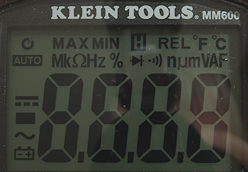
All the segments are shown during power on.
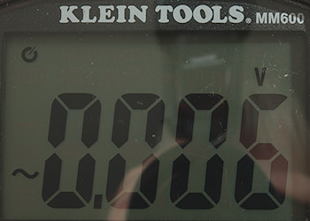
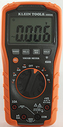
Typical display during usage, it will show the number and selected measurement
Functions
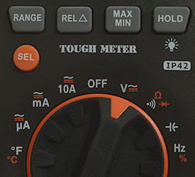
Buttons:
- Range: Manual range, hold down to switch back into automatic ranging.
- Rel: Store current display value and show all new values relative to this value.
- Max/min: Capture max and min values.
- Hold: Freeze display value.
- Sel (Orange): Select functions with orange text: DC V/A, ohm, diode, duty cycle, Celsius.
Rotary switch:
- °F °C: Show temperature, this is an American meter and starts in Fahrenheit.
- uA: Microampere range, starts in AC
- mA: Milliampere range, starts in AC
- 10A: Ampere range, starts in AC
- Off: Turns meter off.
- V: Shows voltage, starts in AC
 : Continuity, ohm and diode (It starts in Continuity).
 : capacitance
- Hz: Show frequency and duty cycle.
Input
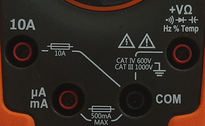
- 20ADC: 20A current input.
- mA uA: Lower current input.
- xxx: All other ranges
- COM: The common terminal for all ranges
Measurements
- Volt and frequency
- 5V AC readings is 5% down at 2.2kHz
- Input impedance is 10-11Mohm
- At 100mVrms input frequency range is from 1Hz to 500kHz
- Duty cycle works from 5% to above 94% at 100kHz with 1Vpp, precision is within 5 (Higher amplitude will improve precision slightly).
- Duty cycle works from 1% to above 99% at 10kHz with 1Vpp, precision is within 0.3 (It is spot on, except the lowest and highest few percent).
- Max/min needs about 500ms to capture a voltage.
- Frequency counter requires a zero crossing.
- Frequency input is 1-3Mohm up 1.5V, then it drops to 40kOhm at 2.5V and 3kOhm at 25 volt.
- Input protection is 1000V DC/AC
- Current
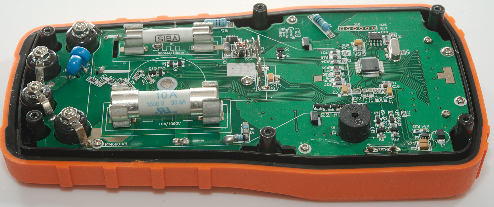
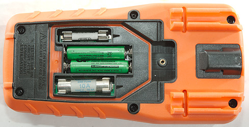
- 10A range is fused with a 10A/1000V 10x38mm fuse
- mA range is fused with a 0.5A/1000V 6.3x32mm fuse
- 10A range has an audible alarm at 10A or above.
- Ohm, continuity, diode and capacitance
- Ohm needs about 3s to measure 100ohm
- Ohm voltage is 1.0V open and 0.25mA shorted.
- Continuity is very fast (About 6ms).
- Continuity beeps when resistance is below 50ohm.
- Continuity is 1.0V open and 0.25mA shorted
- Diode range uses 3.3V, max. display is 3.000V at 0.09mA, max. current is 1.0mA shorted
- Input protection is 600V DC/AC
- Meter uses about 6 seconds to measure 1000uF
- Miscellaneous
- Current consumption of meter is around 1.4mA (17mA with backlight)
- Meter turns off at 2.2V, battery symbol show at 2.4V.
- Backlight stays on with stable brightness independent of battery voltage.
- Readings are correct until the meter turns off.
- Viewing angle is good, except from the top
- Display updates around 3 times/sec
- Will automatic turn background light off in about 180 seconds.
- Will automatic turn power off in about 30 minutes.
- Standard probes fits in the meter.
- The meter usual need a couple of display update to reach the final value.
- Weight is 418g without accessories, but with batteries.
- Size is 178 x 90 x 53mm
- Probes
- Probe resistance 23mOhm for one (This is very low).
- Probe wire is 80cm long.
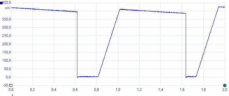
A look at the capacitance measurement waveform for 1uF.
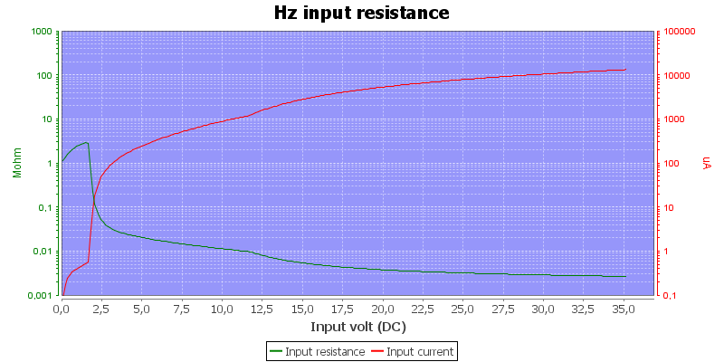
Frequency input impedance.
The meter is true-rms.
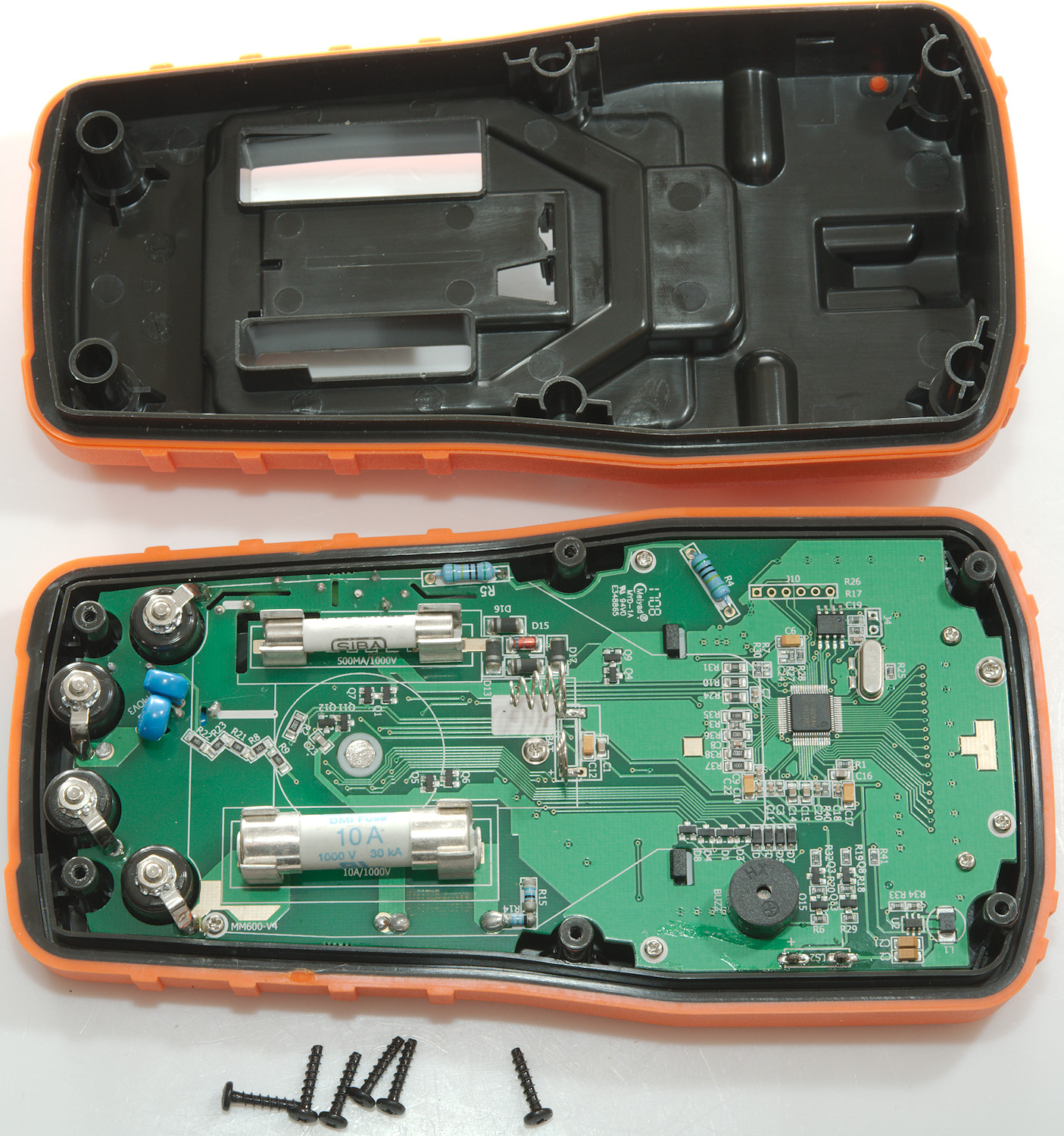
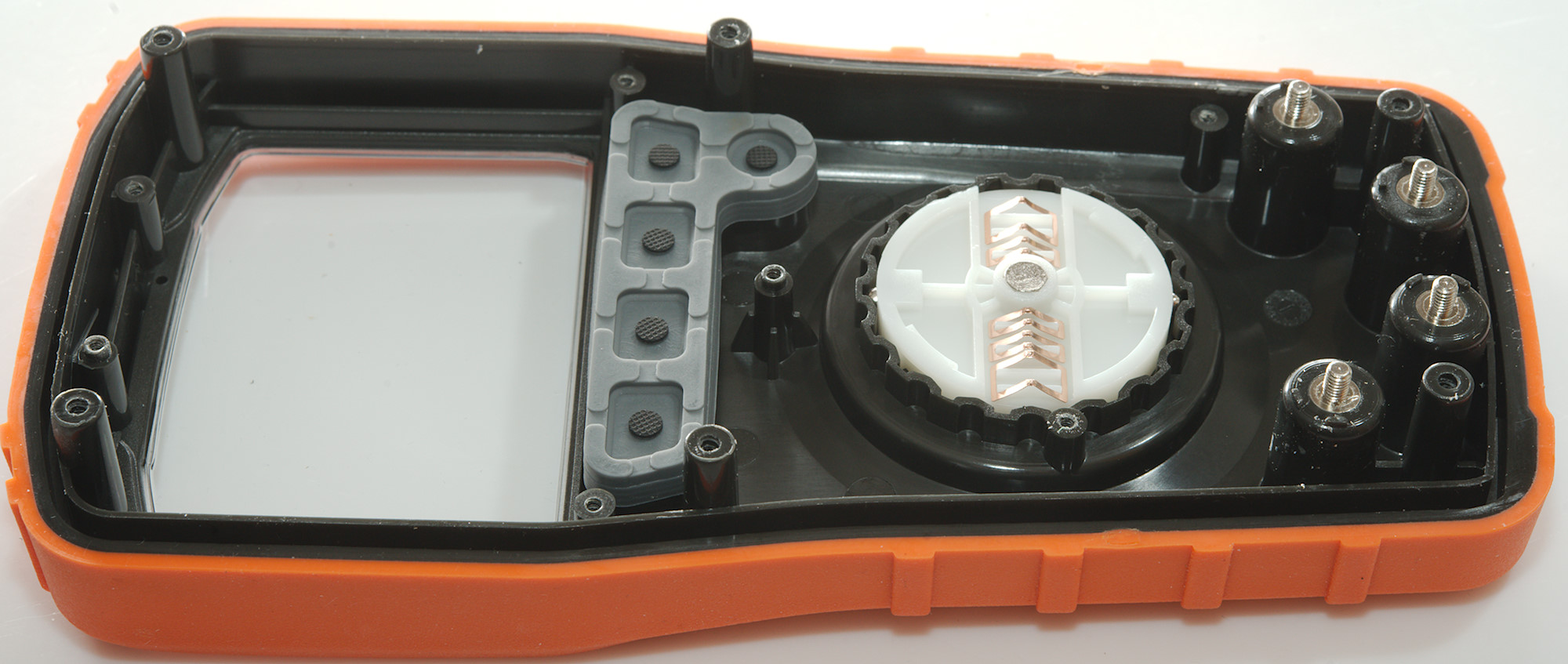
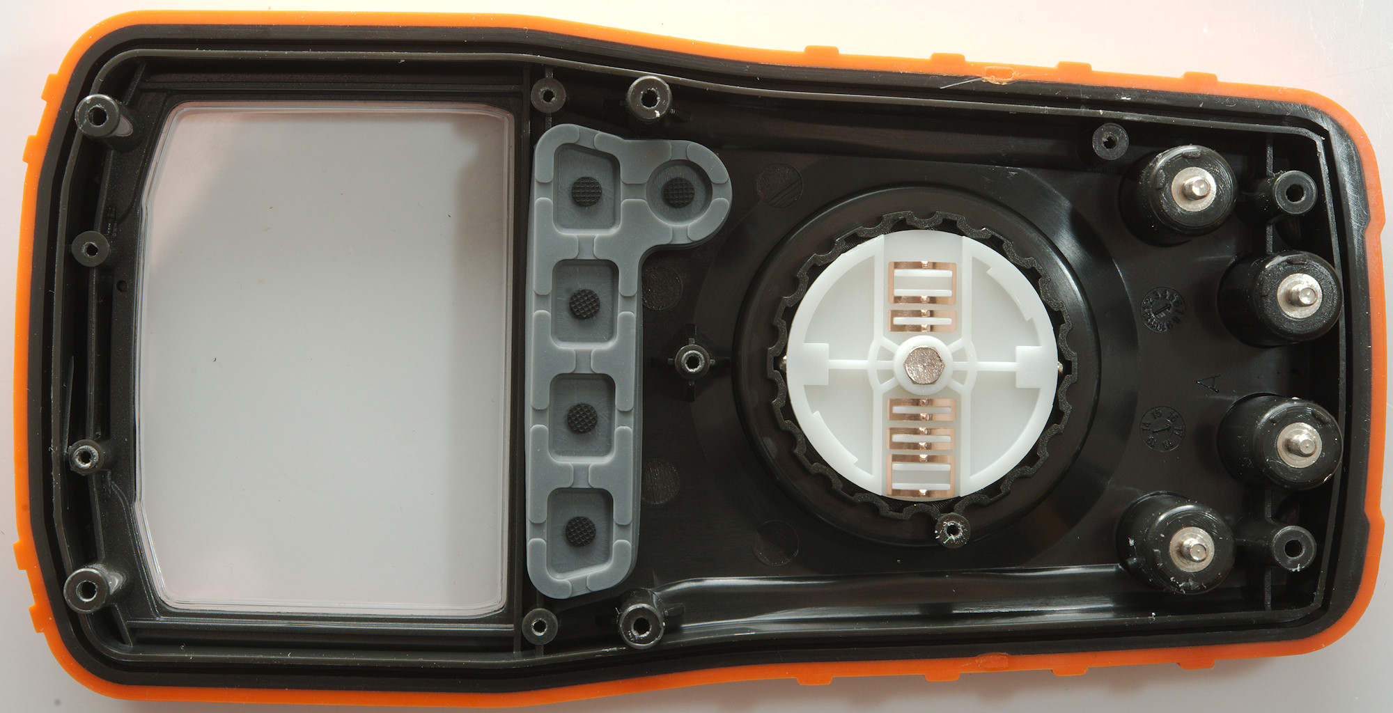
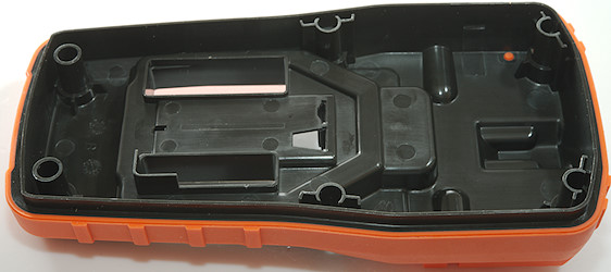
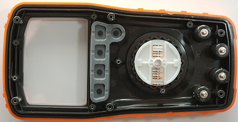
Tear down
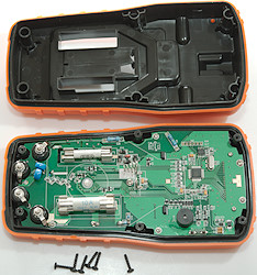
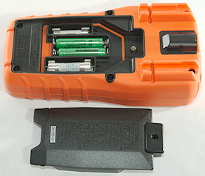
I had to remove the batteries and 6 screws, before I could open the meter.
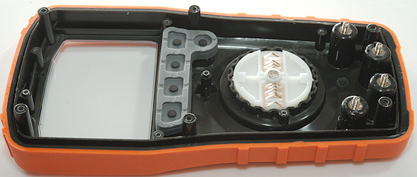
A corner of the plastic around the small fuse fits into a slots in the circuit board
As usual the circuit board is shaped to fit the enclosure.
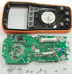
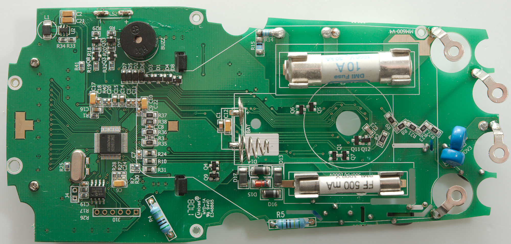
Getting the circuit board out was 4 nuts and 7 screws, this meter is made to be tough.
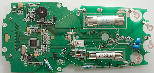
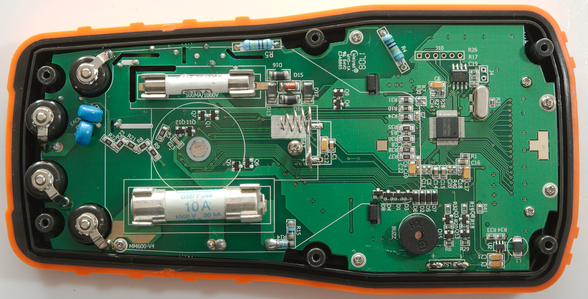
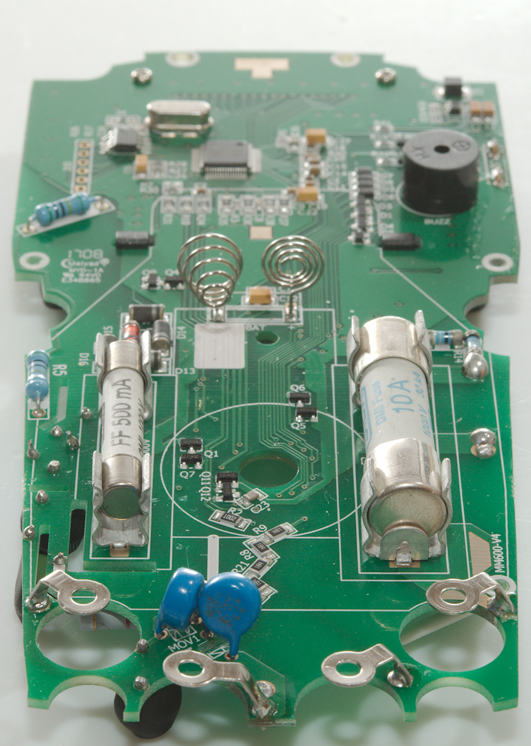
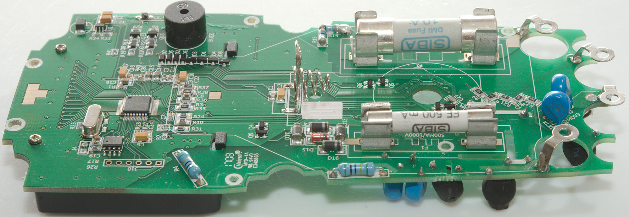
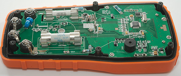
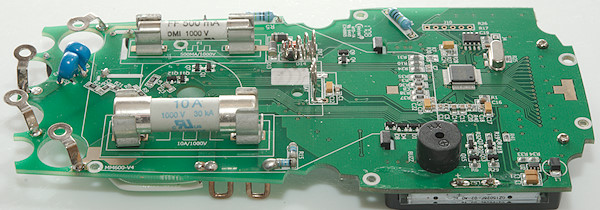
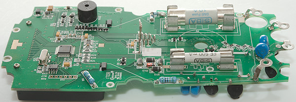
The resistors in zig-zag (R8, R9, R21, R22, R23: 5*180K->0.9Mohm) is one of the input chains, it is also protected by two MOVs and a PTC on the other side. The 10Mohm input chain is R4 and R5 (PTC and MOV is on the other side). There is a lot of transistor pars (Q11 & Q12, Q1 & Q7, Q5 & Q6, Q4 & Q9) for protection.
The four diodes (D13, D14, D16, D17) and the probably zener (D15) is protection of the uA and mA current shunt (R14 & R15).
The main multimeter chip is DM1106EN with a 24LC02B for calibration. It looks like a boost regulator around U2 and L1 to supply the backlight.
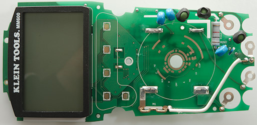
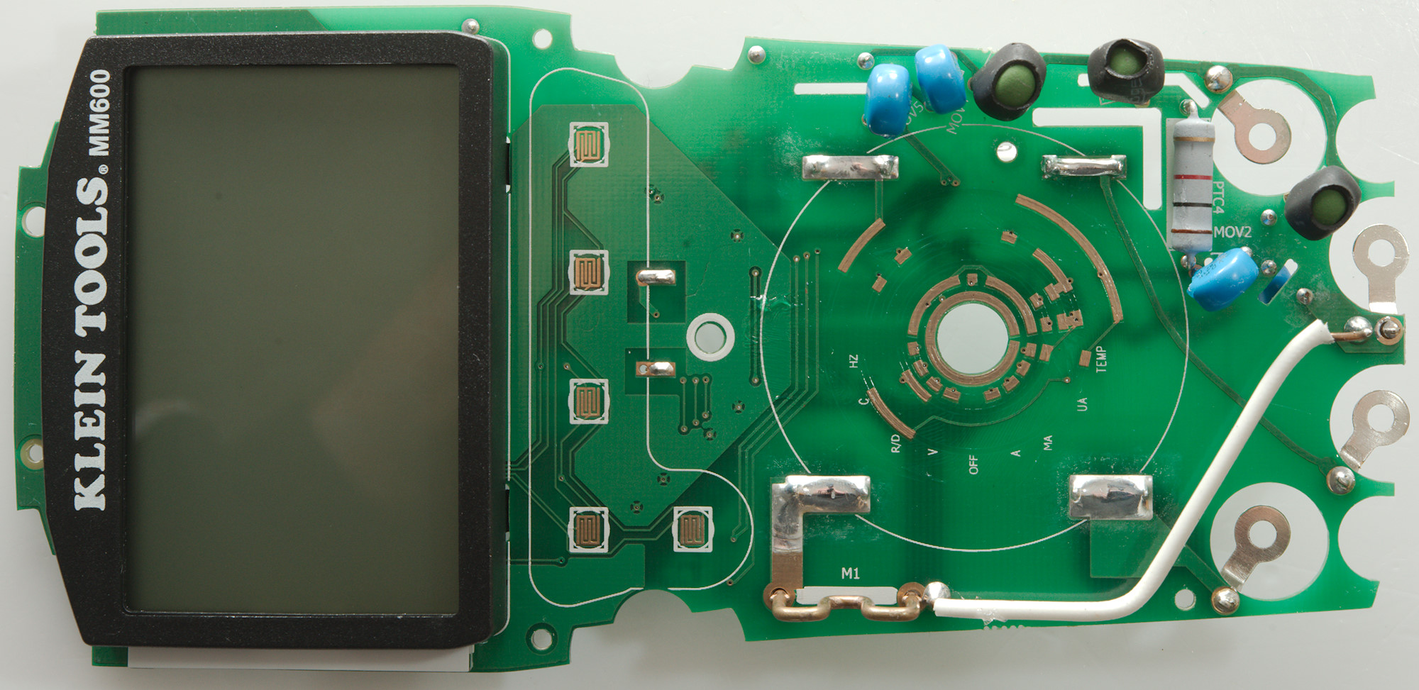
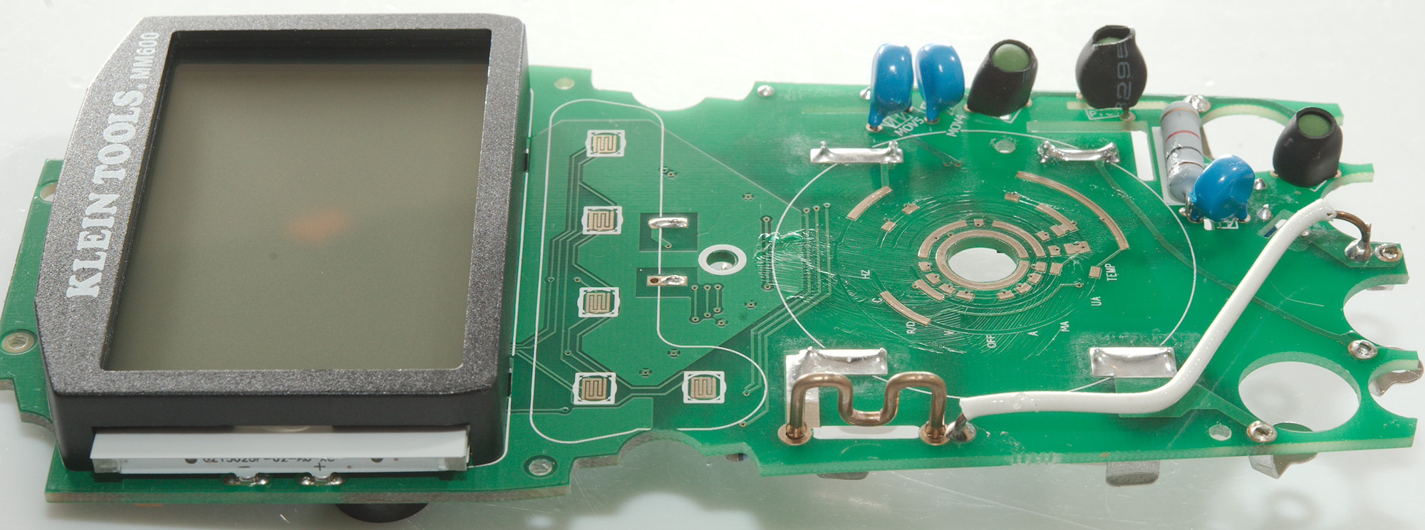
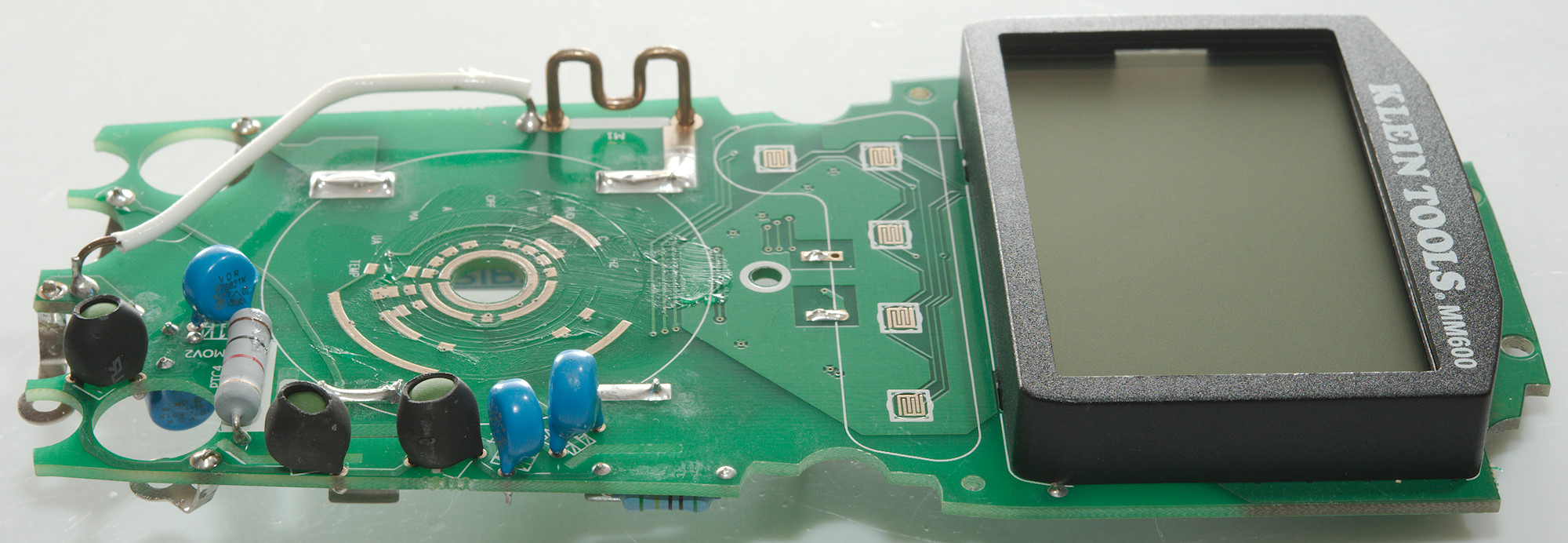
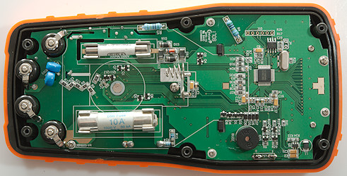
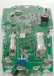
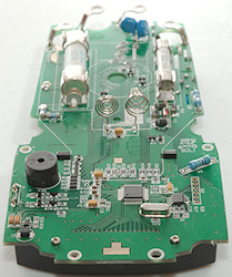
This side is more input protection, including the ohm/capacitance range, that is handled by MOV2, the resistor and a PTC. It is a very sparse populated range switch.
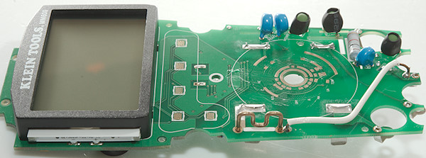

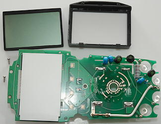

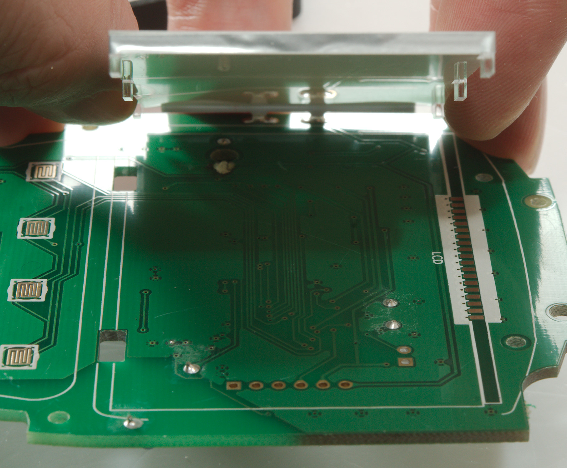
I wanted to check under the LCD display, there was nothing, but the black border on the LCD display is soft rubber.
Conclusion
I am impressed with how solid this meter is constructed. It is made for electrician work (It starts in AC). It has all the common ranges, but for an electricians meter it is missing a Low-Z mode. Frequency is only on AC and always in frequency range, it is not possible to measure in volt or current ranges.
After looking at the meter I believe the "Tough meter" claim.
Notes
How do I review a DMM
More DMM reviews