Performance test and review of 20W DC-DC Step Down Voltage Regulator
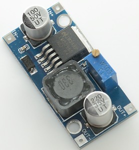
Official specifications:
- Module property:Non-isolation buck
- Rectification mode:Non-synchronous rectifier
- Input voltage:3V-40V
- Output voltage:1.5V-35V
- Output current:Rated current is 2A,maximum 3A (Additional heatsink is required)
- Conversion efficiency:92% (highest).
- Switching frequency:65KHz
- Output ripple:30mV (maximum)
- Load regulation:±0.5%
- Voltage regulation:± 2.5%
- Work temperature:-40 °C - +85 °C
- dimension:43mm*21mm*14mm (L*W*G)
- NOTE:This can't be used to step up Voltage
- size:4*2*1 cm
I found this module on ebay at worldone2012
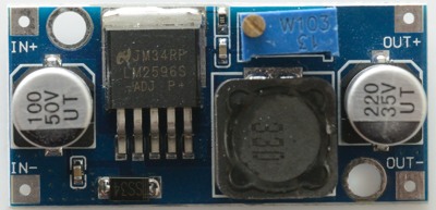
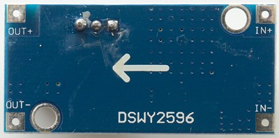
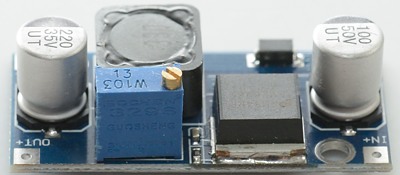
I am not that happy about the trimpot pins sticking through the circuit board, this makes mounting the converter on a heatsink more difficult.
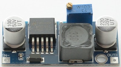
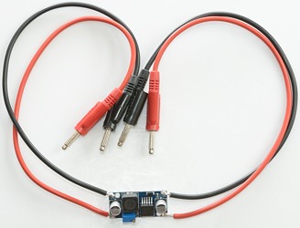
All test was done with these wires, they where plugged into the power supply and the load.
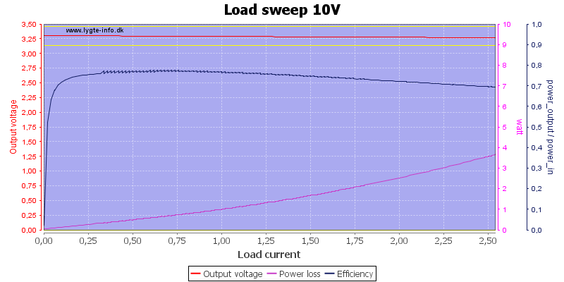
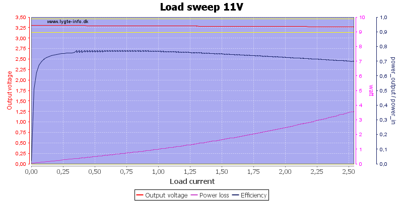
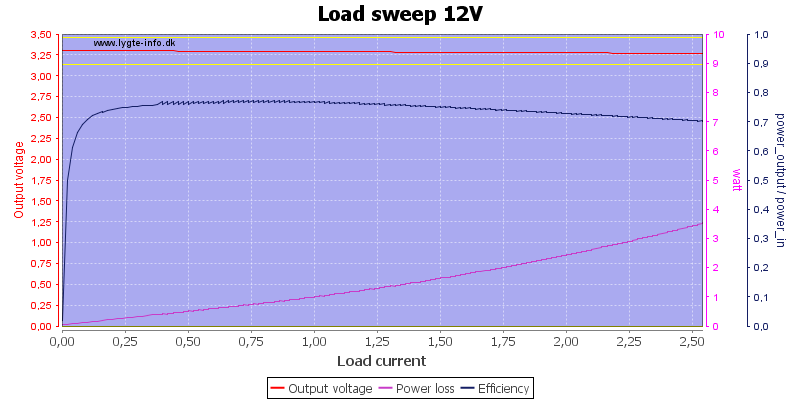
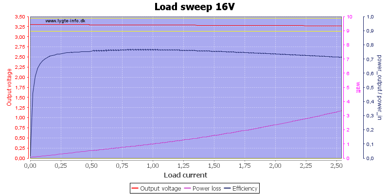
For the test I made some scripts that automatic changes input voltage and current and then let them run. As can be seen I got a lot of curves out of it. Generally there is no reason to check all the curves, just find the ones that apply to your application.
Note: Not all tests are done at all voltages. 5V has 1A thermo photo, there others are at 2A. 3.3V and 5V has scope pictures of the output.
The minimum output voltage I could select was 1.22 volt, maximum voltage above 30 volt. The trimpot is not completely smooth, adjusting within 20mV was sometimes the best possible result.
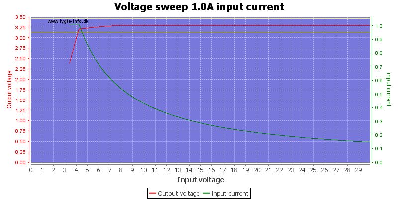
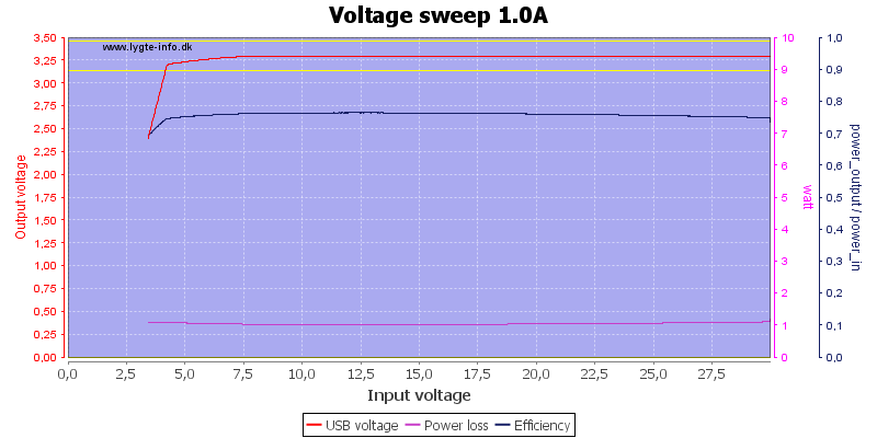
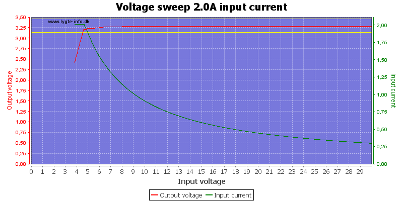
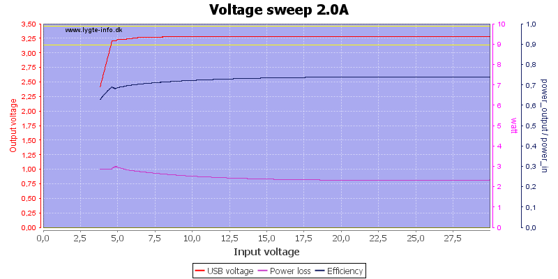
3.3 volt output
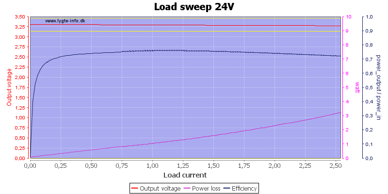
Load sweep with different input voltages
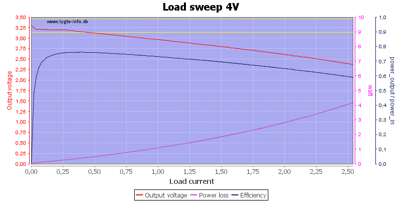
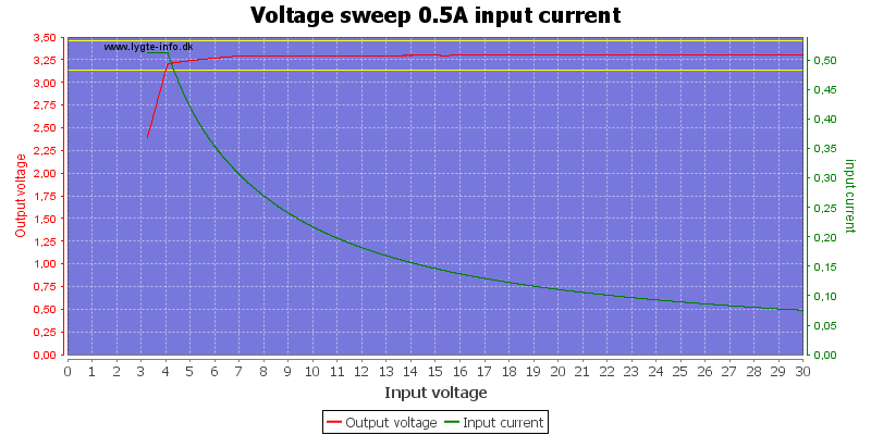
4V input is definitely too low for 3.3 volt output.
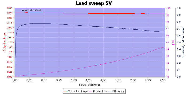
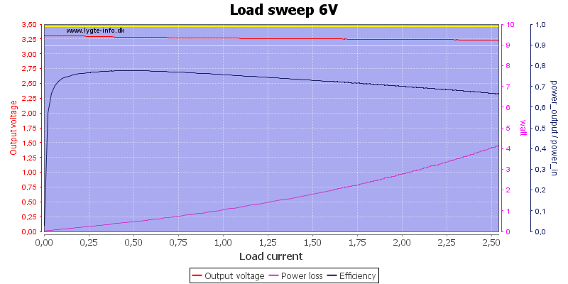
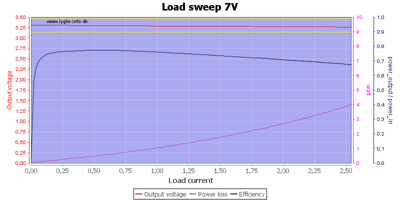
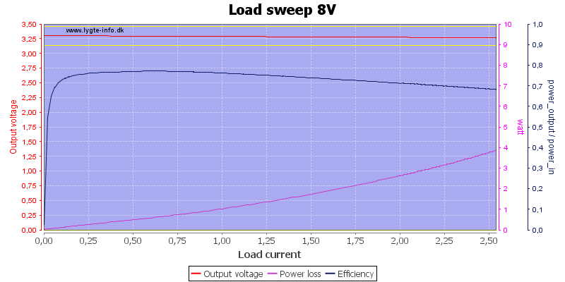
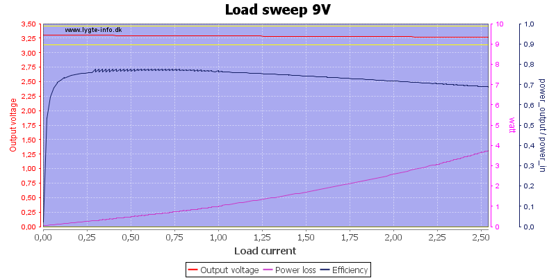
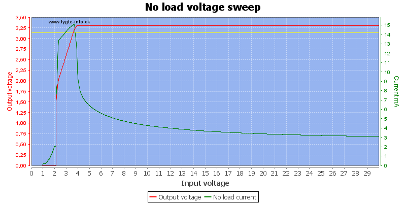
Input voltage sweep with constant current load
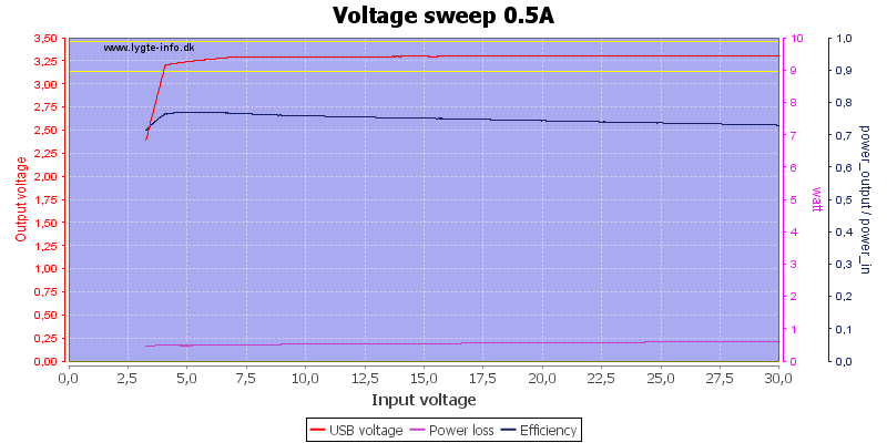
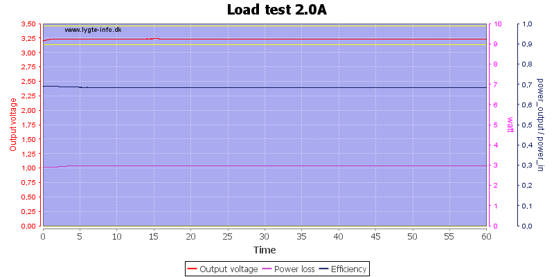
Load test
I uses a 5.0 volt supply for this test.
The photos below are done 45 minutes into the above test.
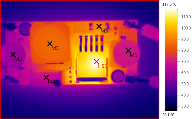
M1: 69,5°C, M2: 56,6°C, M3: 86,3°C, M4: 67,5°C, M5: 90,5°C, HS1: 117,6°C
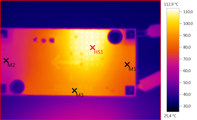
M1: 82,9°C, M2: 65,8°C, M3: 91,4°C, HS1: 112,9°C
Output test
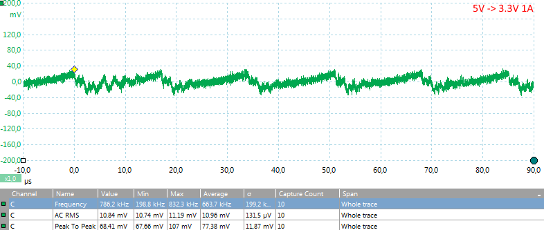
There is some ripple on the output from the switching converter.
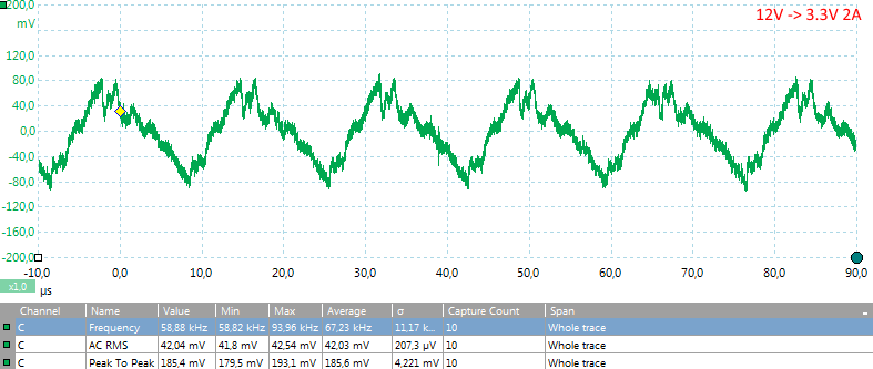
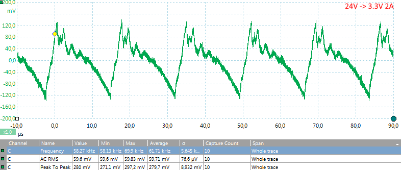
Higher input voltage will increase the ripple.
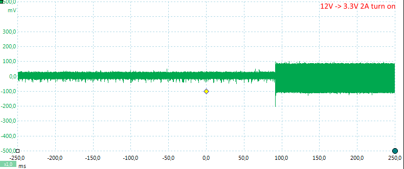
Changing the load from 0 to 2A will give a short voltage drop on the output.
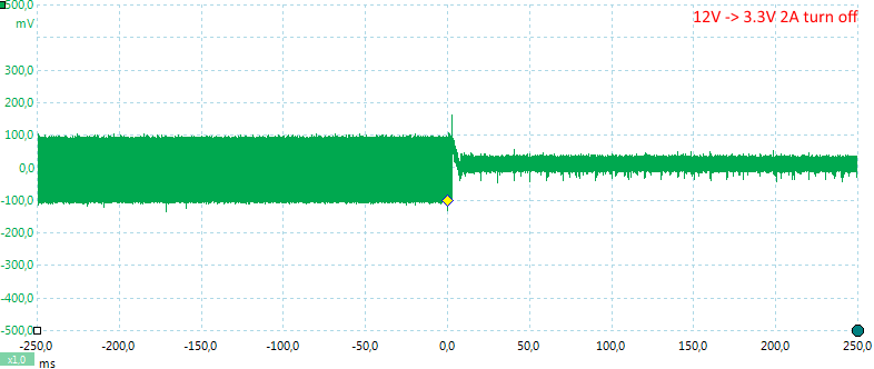
And disconnecting the load again will give a spike.
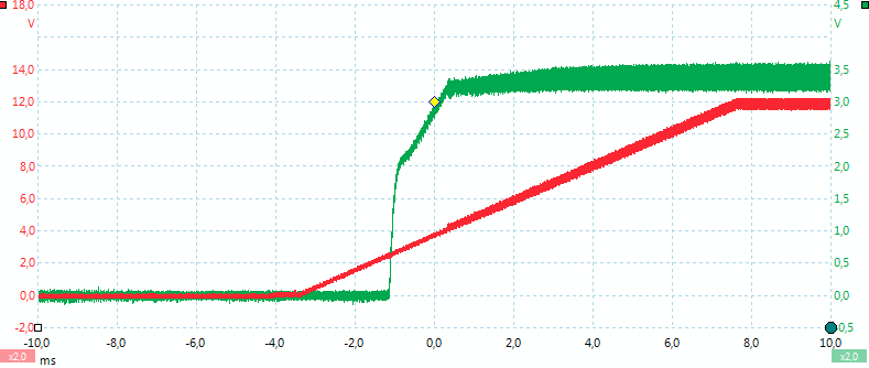
Power on with a 10ohm load.
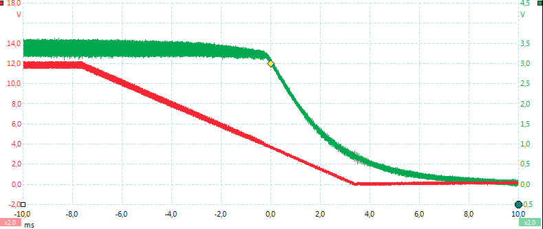
Power off with a 10ohm load.
5.0 volt output
Load sweep with different input voltages

6V input is definitely too low for 5.0 volt output.


Input voltage sweep with constant current load


Load test
I used 12 volt input voltage for this test and has reduced the load current to 1A.
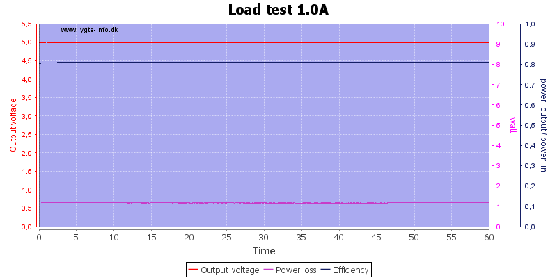
The photos below are done 45 minutes into the above test.
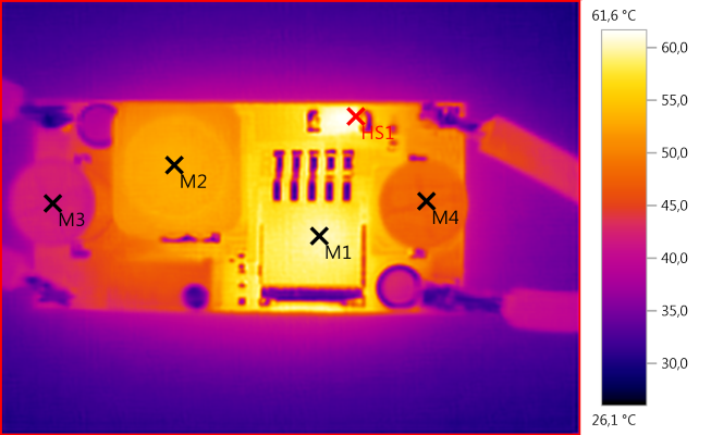
M1: 60,2°C, M2: 53,4°C, M3: 41,3°C, M4: 46,9°C, HS1: 61,6°C
There is no heat problems with this load.
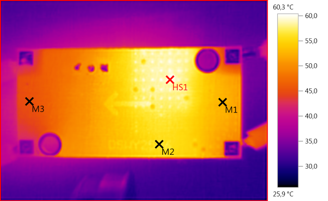
M1: 52,4°C, M2: 56,2°C, M3: 45,1°C, HS1: 60,3°C
Output test
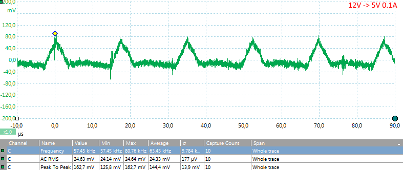
There is some ripple on the output from the switching converter, even at very low loads.
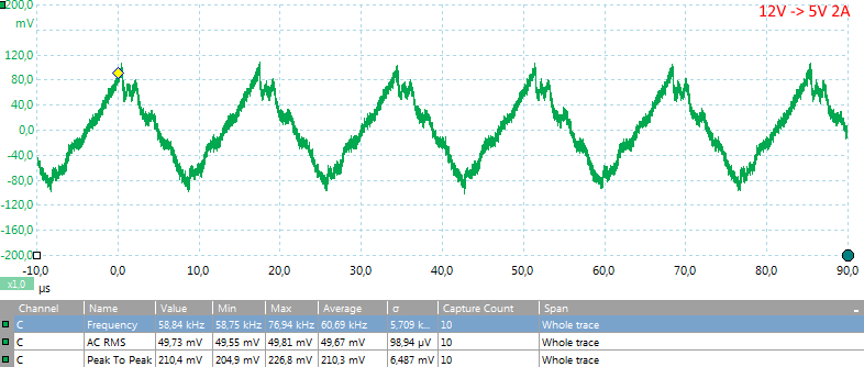
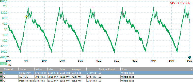
Higher input voltage will increase the ripple.
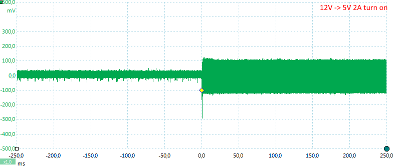
Changing the load from 0 to 2A will give a short voltage drop on the output.
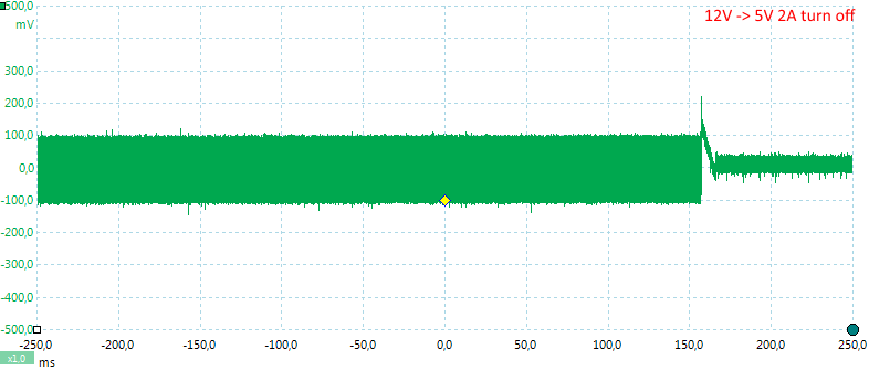
And disconnecting the load again will give a spike.
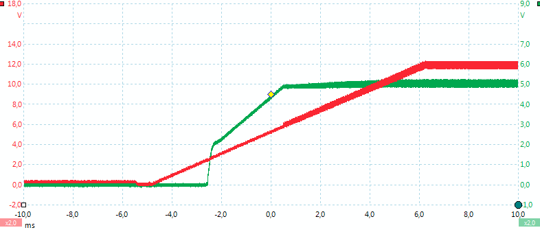
Power on with a 10ohm load.
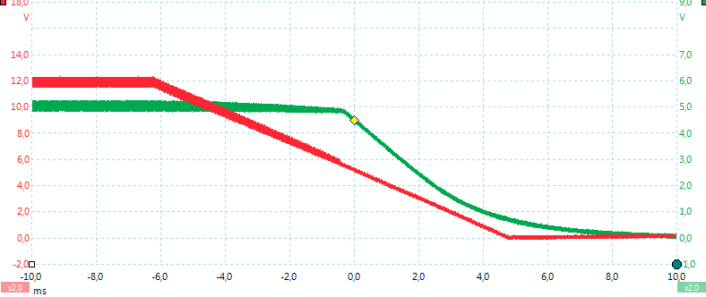
Power off with a 10ohm load.
9.0 volt output
Load sweep with different input voltages

10V input is definitely too low for 9.0 volt output.


Input voltage sweep with constant current load


Load test
I used 12 volt input voltage for this test.

The photos below are done 45 minutes into the above test.
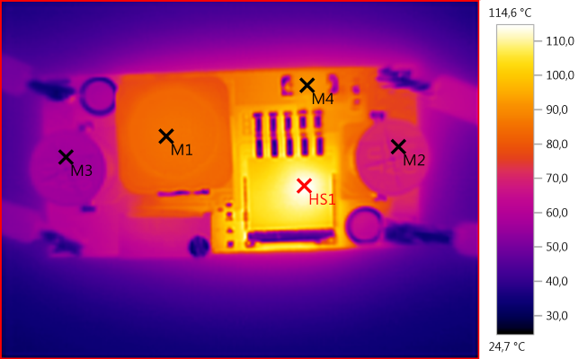
M1: 85,1°C, M2: 70,1°C, M3: 56,4°C, M4: 91,9°C, HS1: 114,6°C
The converter get rather hot when it need to dissipate 3 watt. For a long lifetime I will prefer to use it at lower power levels.
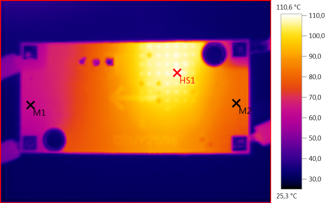
M1: 62,8°C, M2: 81,2°C, HS1: 110,6°C
12.0 volt output
Load sweep with different input voltages


Input voltage sweep with constant current load


Load test
I used 24 volt input voltage for this test.

The photos below are done 45 minutes into the above test.
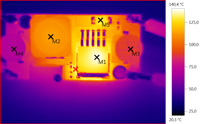
M1: 139,2°C, M2: 113,0°C, M3: 87,0°C, M4: 69,9°C, M5: 129,0°C, HS1: 140,4°C
Here the temperature is way to high, a heatsink may solve the problem.
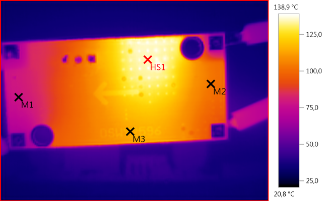
M1: 77,9°C, M2: 102,9°C, M3: 113,1°C, HS1: 138,9°C
Conclusion
The converter can deliver the rated 2A output current, but it gets too hot for a long lifetime, especially with high input voltage the power loss gets bad. At 1A load there is no heat problem.
Generally there is about 200mVpp noise on the output, but it depends on the input voltage and the load.
Notes
The yellow lines are placed +/-5% from nominal voltage.
All the curves are made with a programable power supply and a electronic load.


