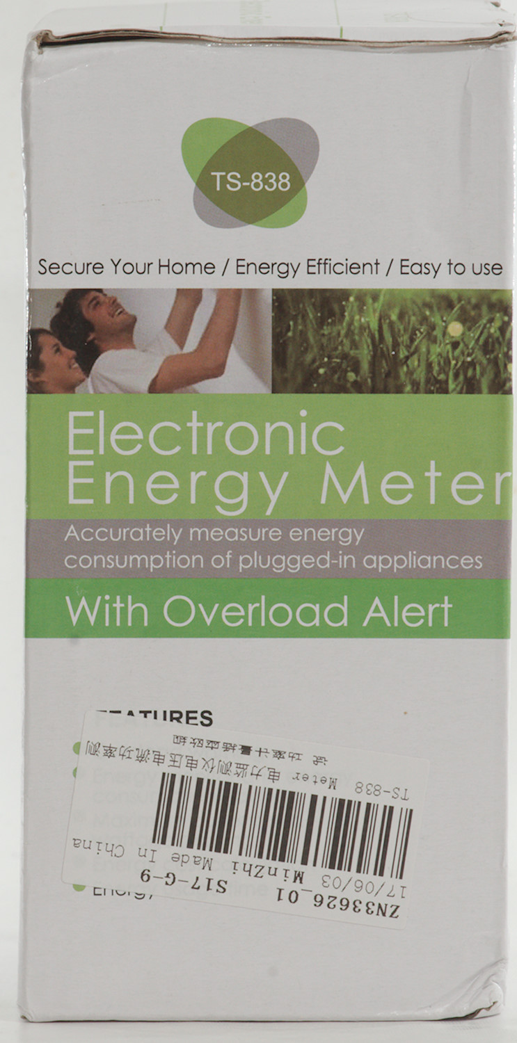
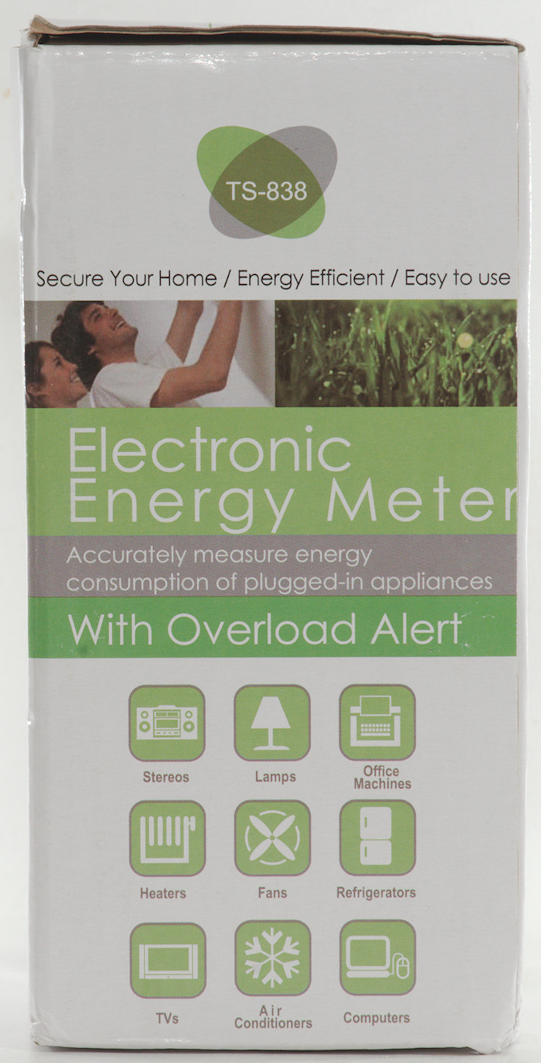
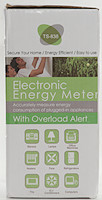
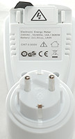
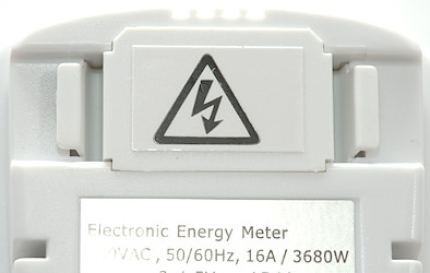
Electronic Energy Meter TS-838
Official specifications:
- Material: ABS
- Color: White + Green
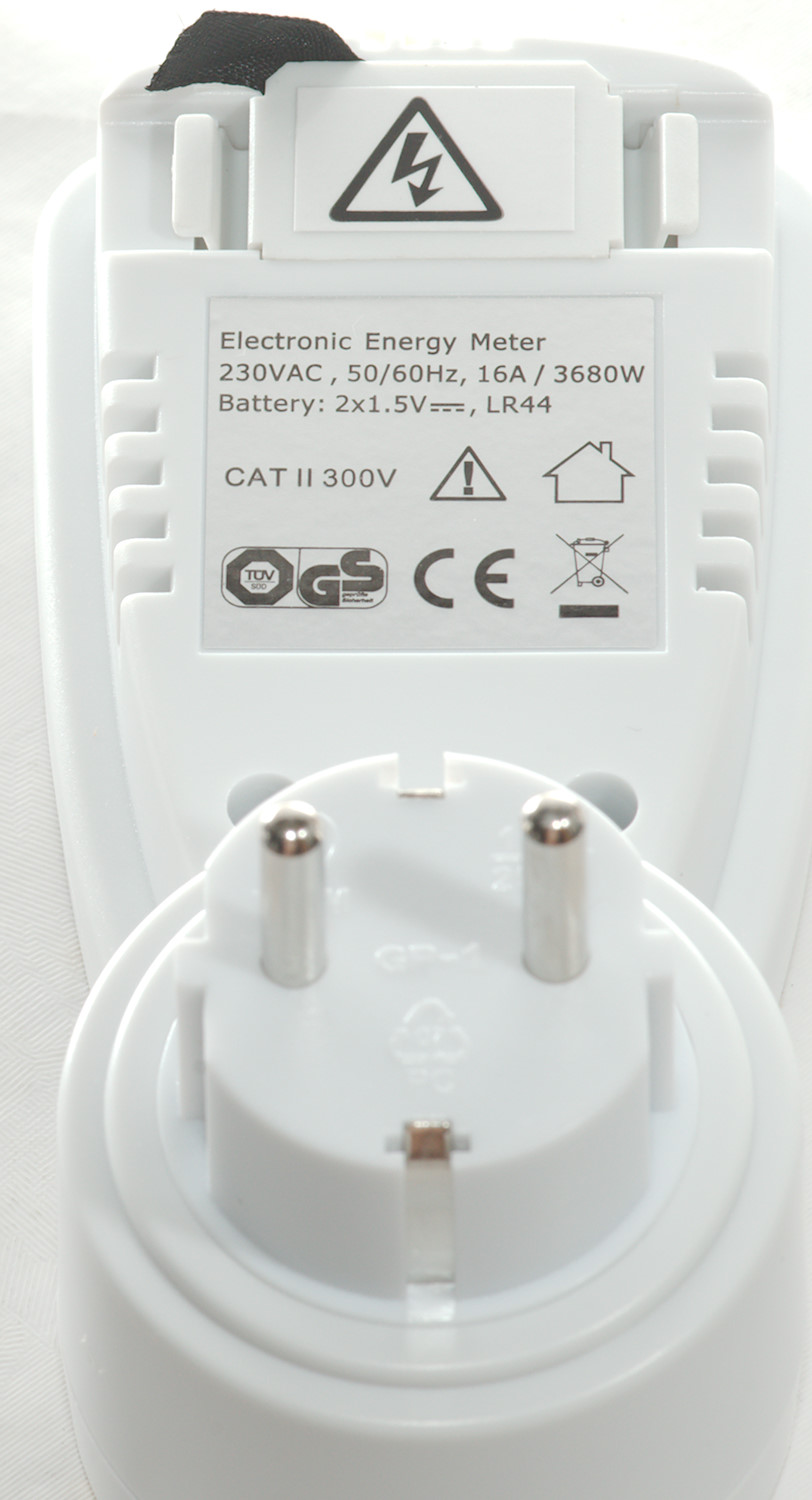
- Power supply: 2* 1.5V Button batteries
- Operating Voltage: 230V 50Hz
- Max Operating Current: 16A
- Min Operating Current: 0.005A
- Voltage Range: 190V to 270V
- Duration of Indication: 0 second to 9,999 hours 59 minutes
- Power Range: 1W to 3680W
- Current Range: 0.01A to 19.999A
- Frequency Display: 0Hz to 9999Hz
- Resolution: 0.5W
- Indication of Frequency: 46Hz to 65Hz
- Measurement of Consumption: 0.00KWH to 9999.99/KWH
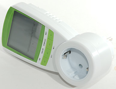
This is a power meter from Aliexpress dealer haron.k-2, how well do it work?
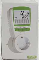
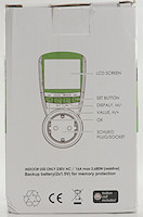
It is delivered in a cardboard box with some specifications on.
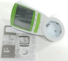
Inside the box is the meter and a 40 pages English instruction manual
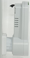
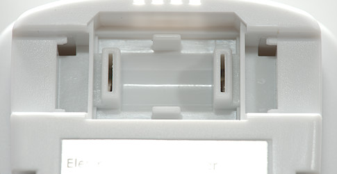
The black strip seen on the pictures above must be removed before the meter can be used.
The strip is used to prevent current draw from the batteries.
The mains voltage is not easily accessible inside the battery compartment (good).
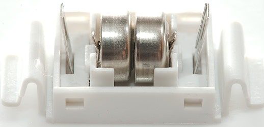
It uses two LR44 batteries.
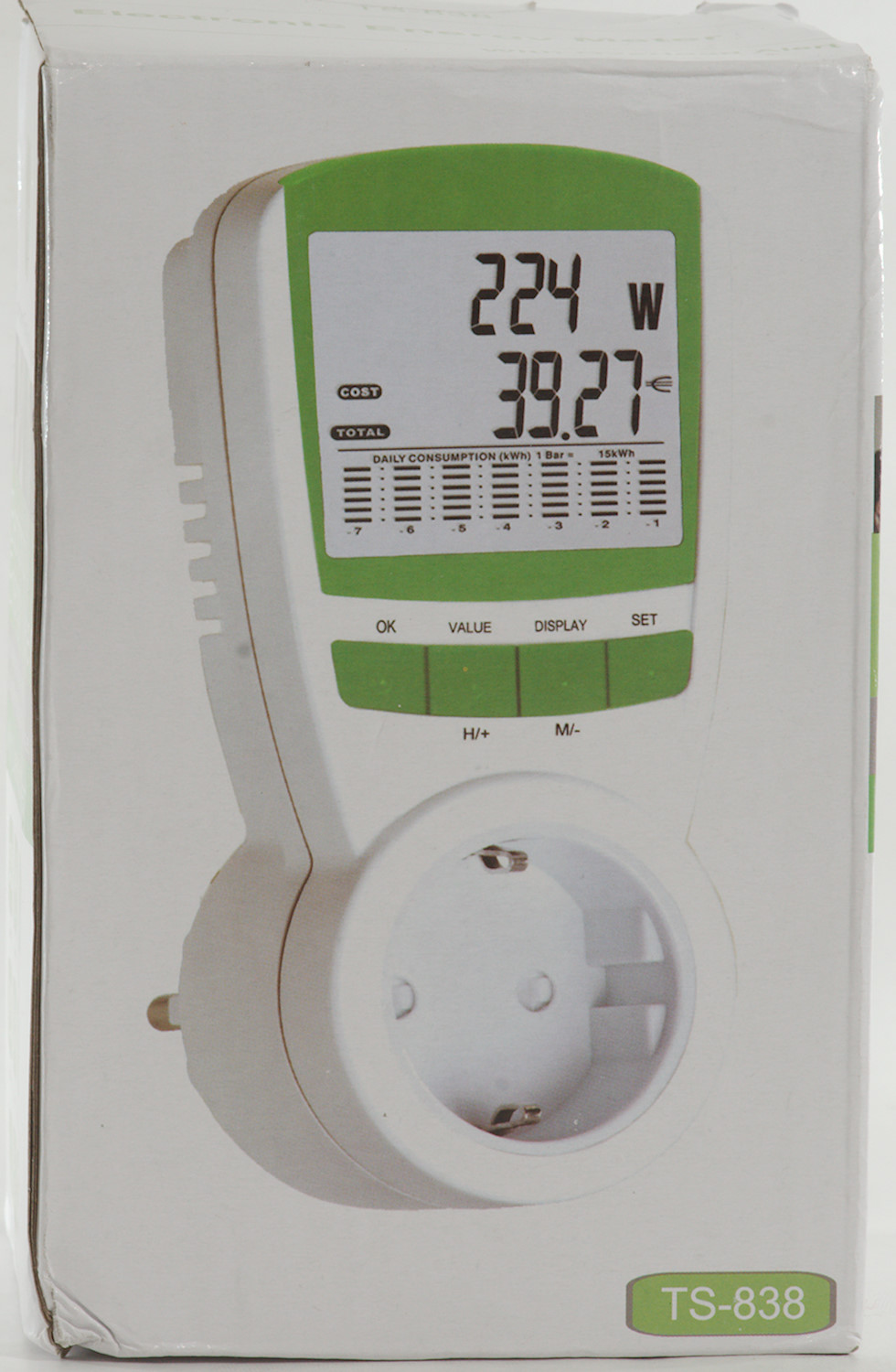
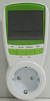
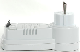
User interface
This power meter has a very simple user interface, most of the time only one button can be used. Only exception is when the electricity price must be configured and to reset the device.
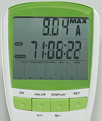
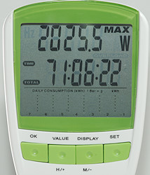
The VALUE key will change the top line between:
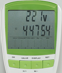
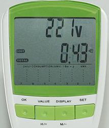
- V: Mains voltage
- A: Actual current draw
- Max A: Maximum current draw measured (Hold down OK to reset)
- W: Actual power user
- Max W: Maximum power measured (Hold down OK to reset)
- A overload: Alarm setting (Hold down SET to adjust)
- Hz: Mains frequency, will be 50 or 60 depending on country.
- cos phi: Power factor
The Display key will change the center line between:
- Time: Time of day (Hold down SET to adjust)
- kWh total: User energy.
- Cost kWh: Price for one kWh (Hold down SET to adjust), it is possible to enter day/night prices.
- Cost total: Total cost for used energy
- Time total: Time with current draw
The bottom line shows the energy consumption for the last 7 days, but the scale only works for devices that uses a lot of energy. My fridge did not register (It uses about 1kWh/day).
Measurements
- Power consumption when idle at 230VAC: 0.7W 24.2mA PF=-0.13
- Power consumption when idle at 120VAC: 0.22W 12.6mA PF=-0.14
- Voltage readout about 3 volt low.
- Readout backed by a battery, i.e. it will not reset when power is removed.
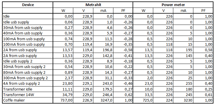
The meter is not for measuring low power devices, the readout works in 0.5W steps. It needs a couple of watt before the readout is acceptable.
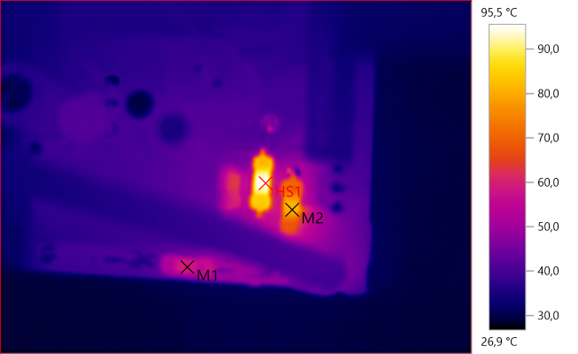
M1: 59,1°C, M2: 80,4°C, HS1: 95,5°C
With only about 0.7 watt in power consumption I would not expect anything to get hot, but it looks like most of the power is dissipated in two resistor that gets rather hot. The circuit board has space for a larger resistor where the hottest one is.
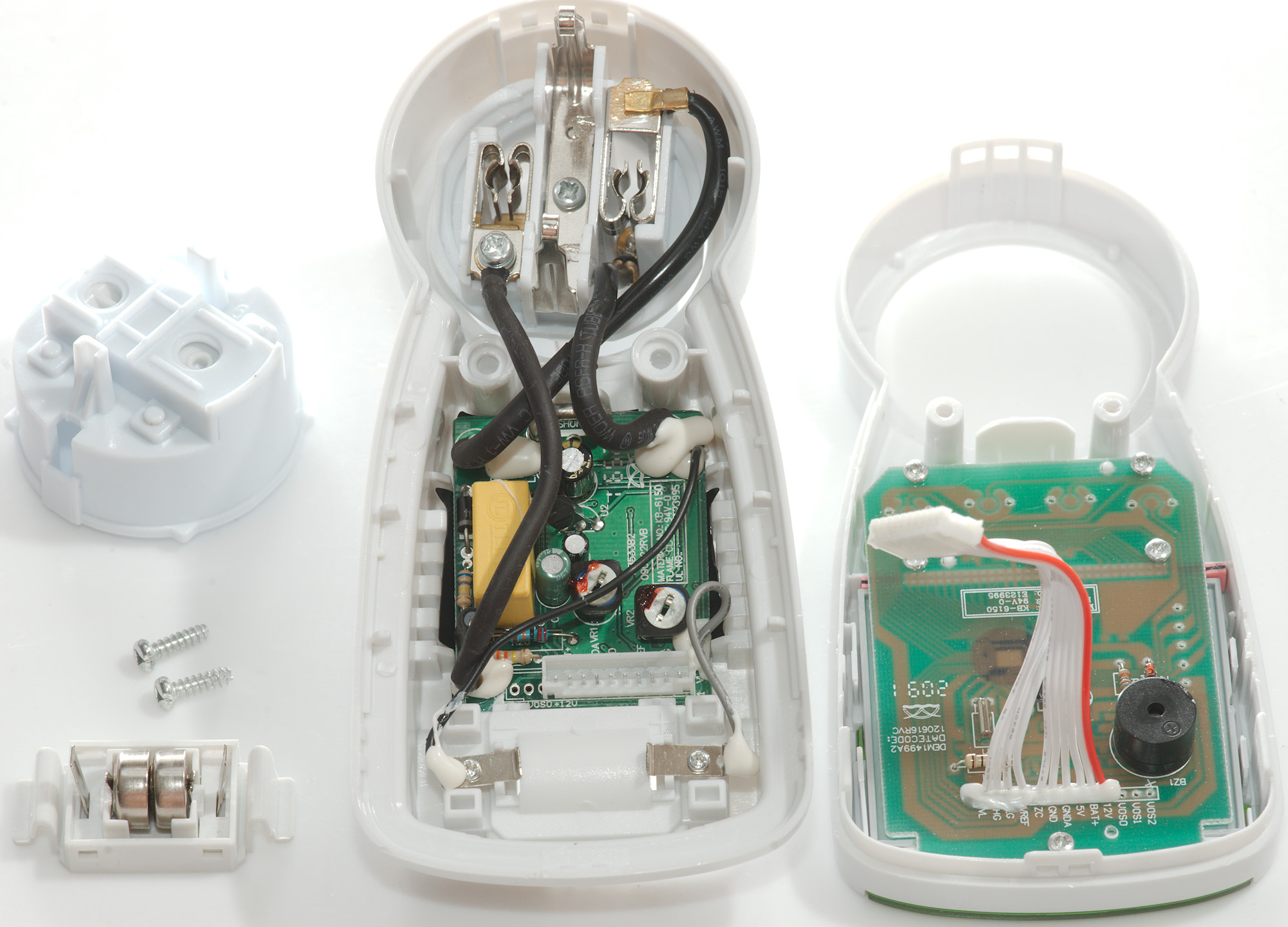
Tear down

Two screws and I few clips before I could open it.
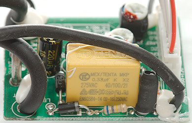
The circuit is directly connected to mains, it do not use any transformer.
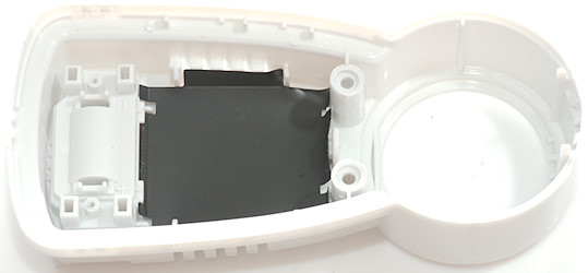
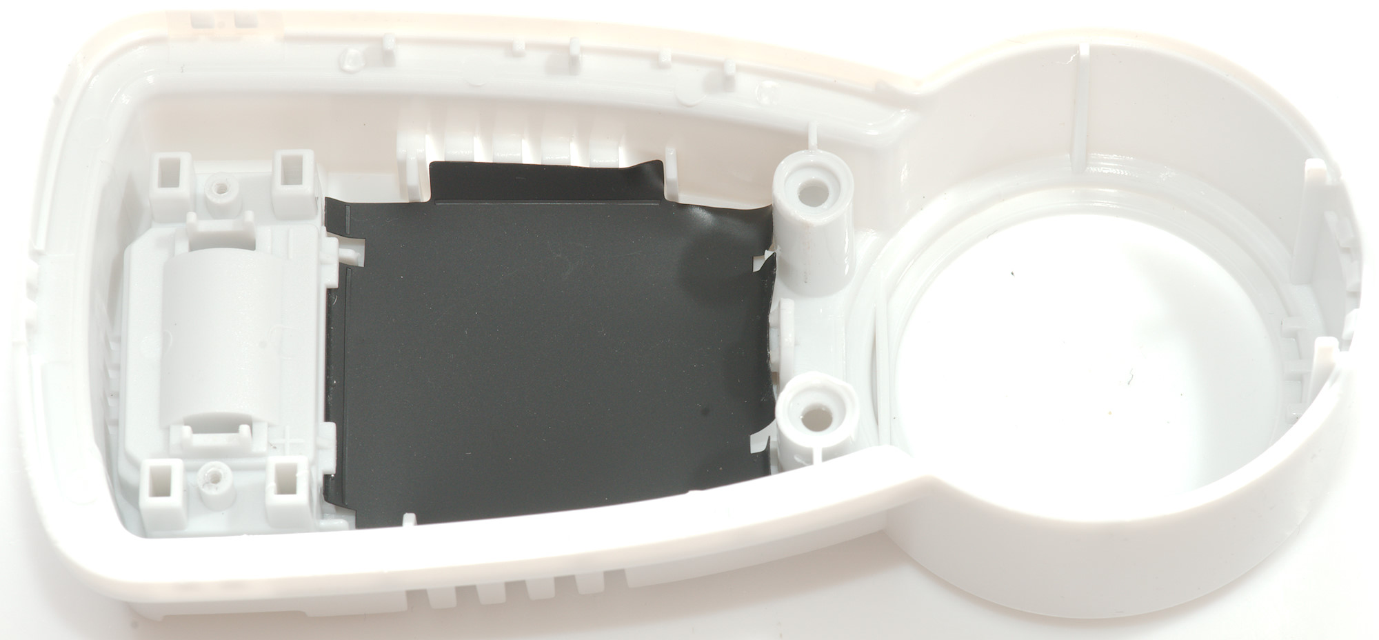
I wonder if the black paper behind the circuit board is to add some isolations for the grills.
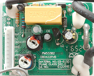
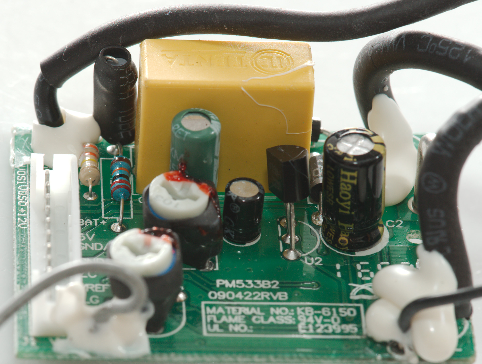
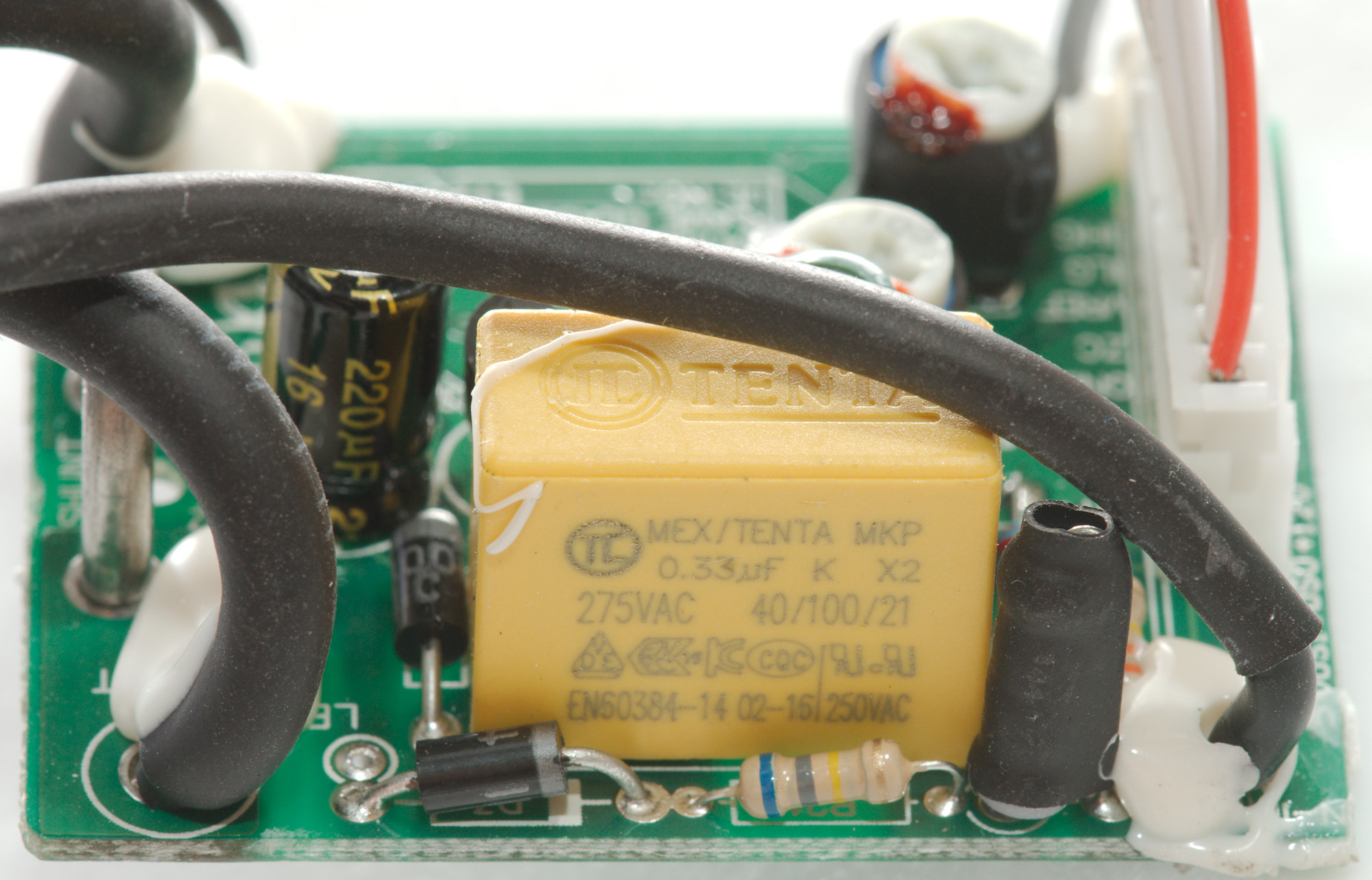
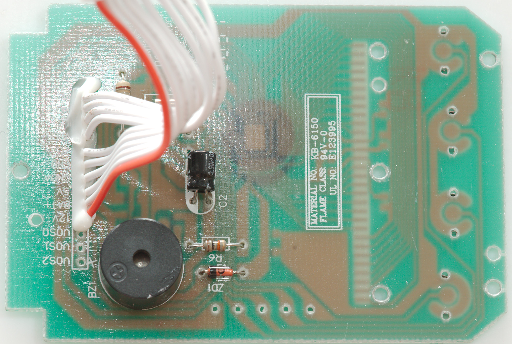
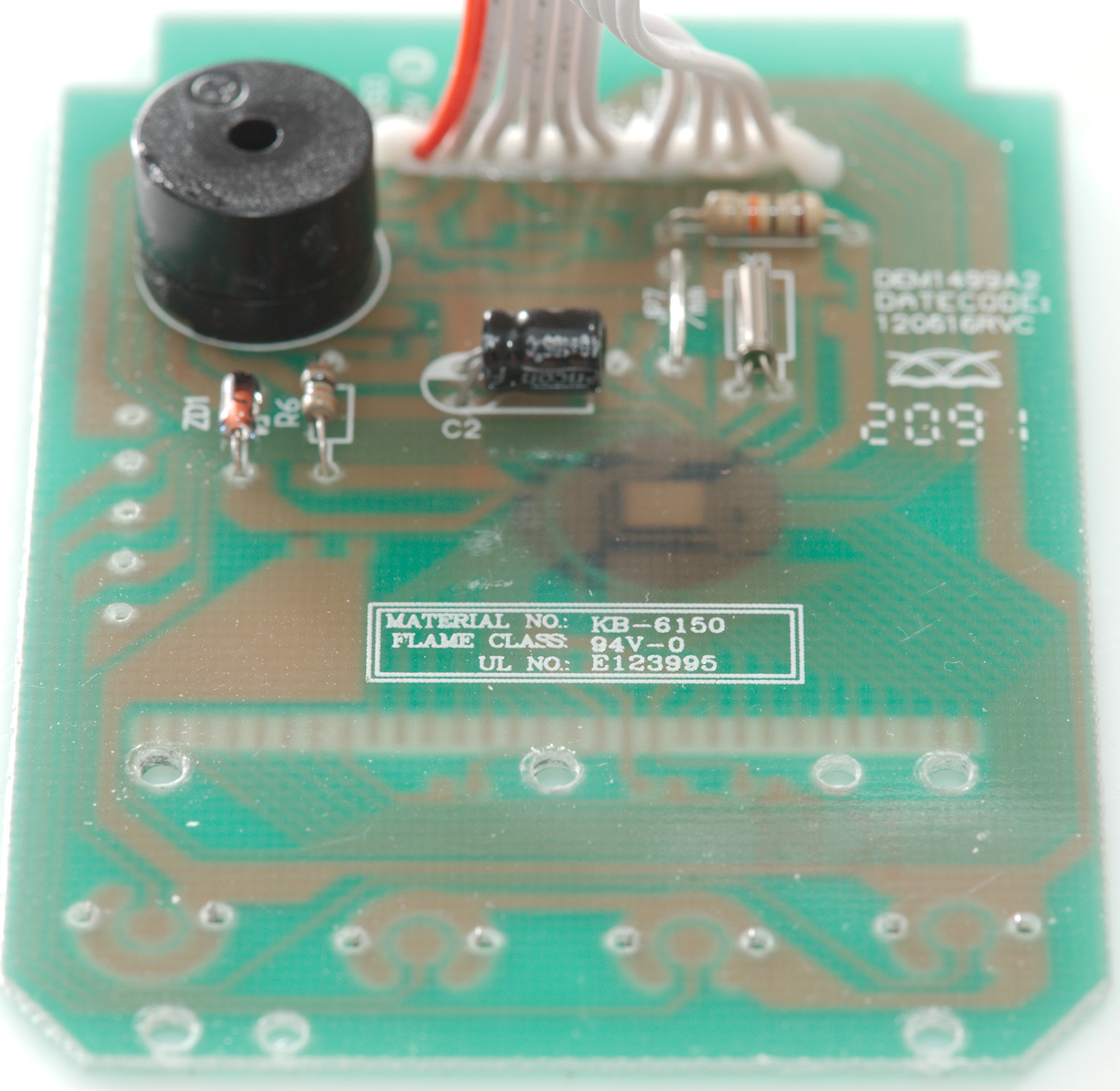
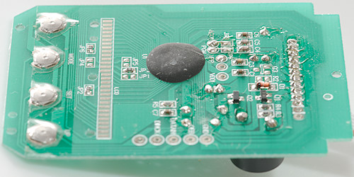
On this side of the circuit board is the power supply, this is a capacitor (C1), resistor, electrolytic capacitor and diodes. The voltage is regulated with a standard 5V voltage regulator (U2:HT7150A). The current shunt is marked SHUNT.
It looks like the current and voltage is adjusted with trimmers (VR1 & VR2).

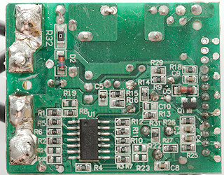
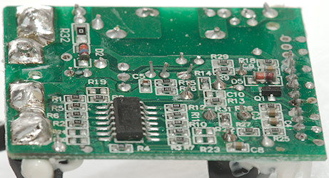
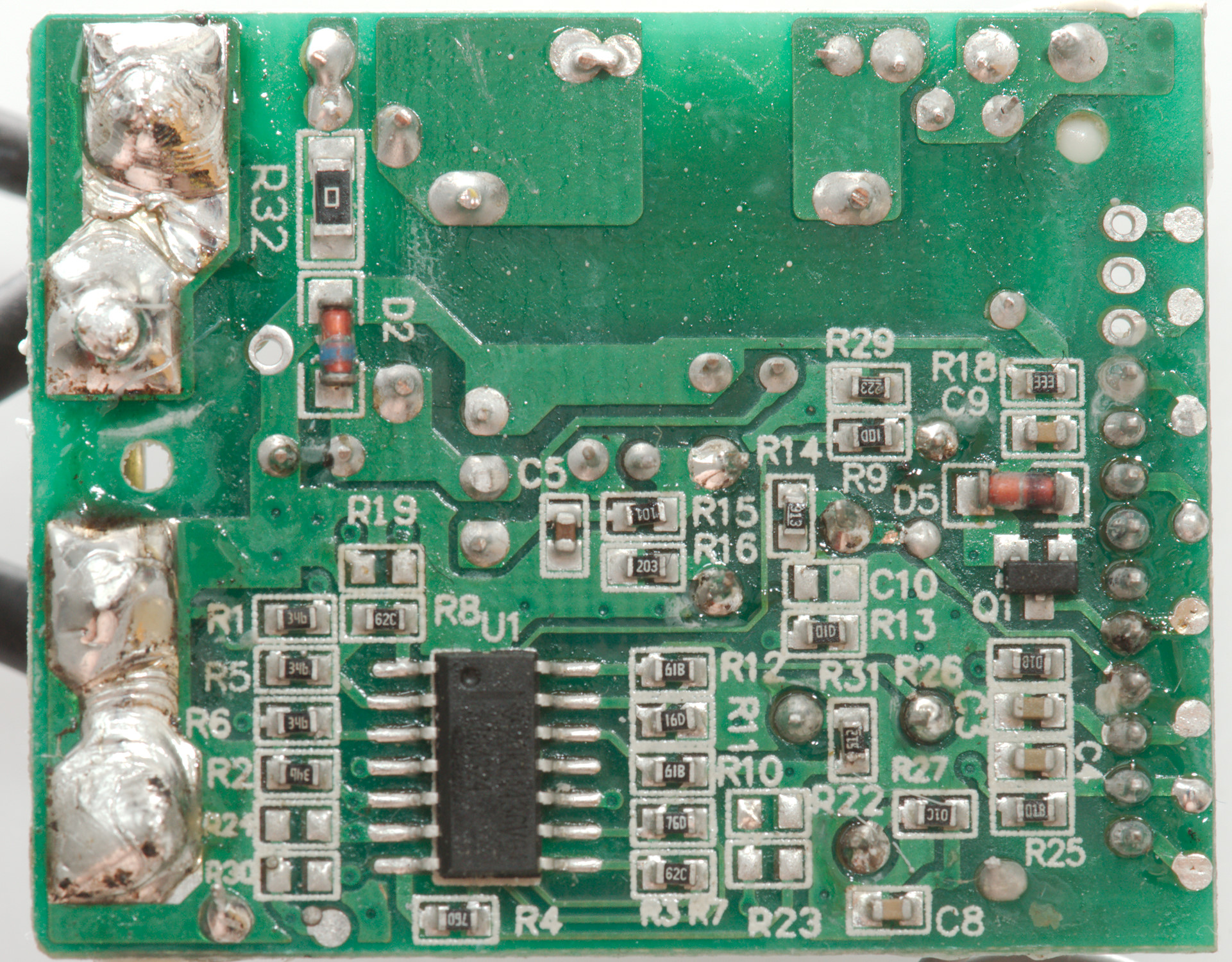
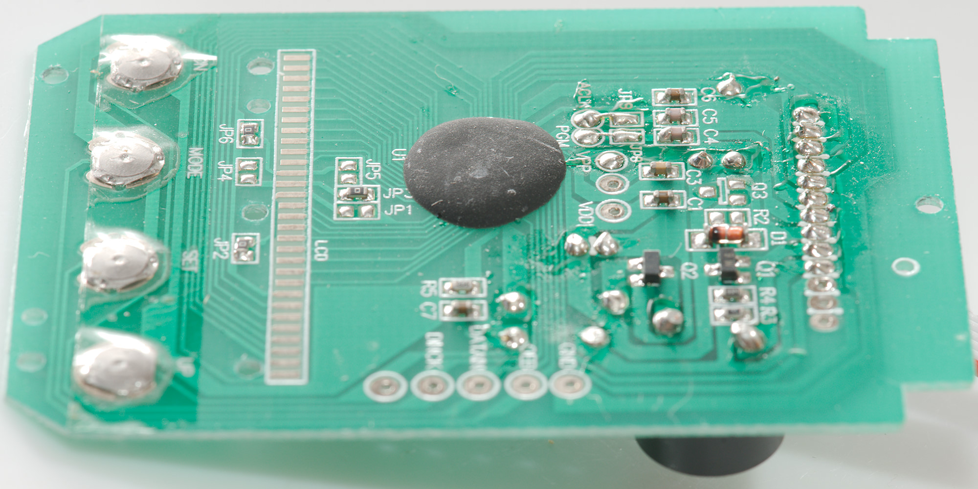
The other side of the circuit board contains the "power meter chip" (U1:LM324) and supporting parts.
There is not much power meter in that chip, it is just 4 amplifiers, this means everything is done on the display board.
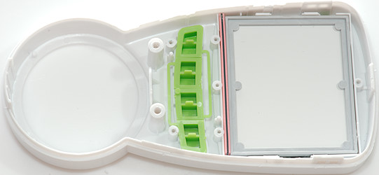
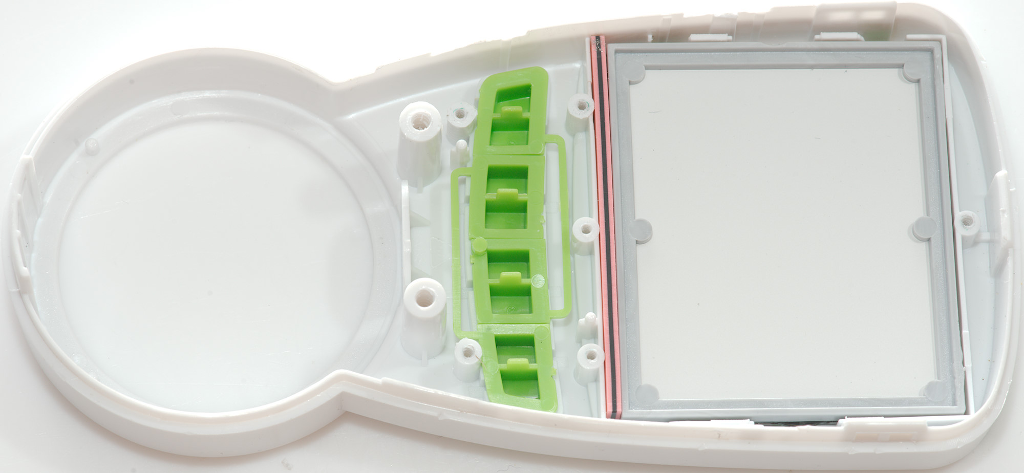
The display sections contains the four buttons and the LCD display connected with a rubber (zebra) strip.

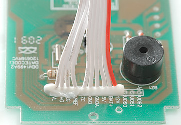
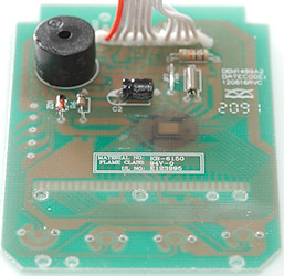
Here is the buzzer for over current alarm.
The small round metal can is a crystal for the main processor.
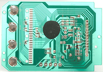
On the display side is the main processor, it is a COB (Chip on board), this means a chip bonded directly on the circuit board and then covered in some usual black stuff.
There is also the domes for the four buttons, with labels that do not match the actual functions.
Conclusion
For a cheap power meter this one is acceptable, but it is not good at low power and the voltage is a bit off (I will not recommend to trim it, the trimpot is directly connected to mains power).
The hot resistor is a bit problematic, it is not too hot for a resistor, but I believe it is used to measure the mains voltage and a hot resistor is not as stable as a cold resistor.
Notes
The error in readout will probably not be present on all devices, but shows that the calibration is not well done.