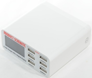
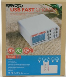
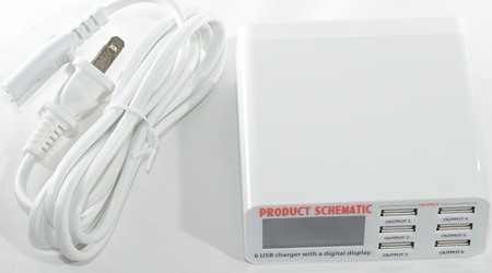
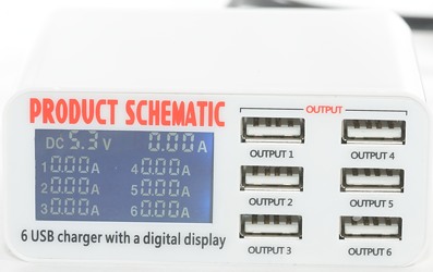
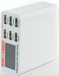
Usb fast charger 6 port WLX-899
Official specifications:
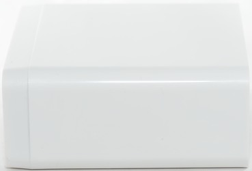
- Material: ABS
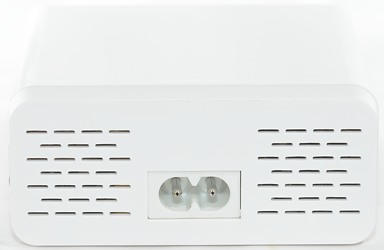
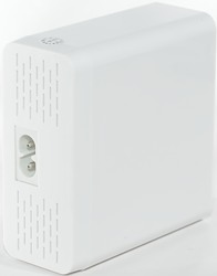
- Shade Of Color: White
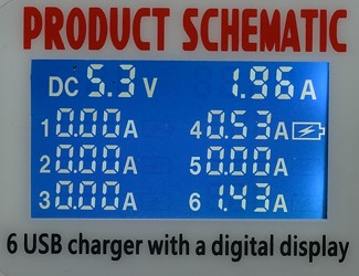
- Indicator Light: Yes
- Port Number: 6
- Current Output: 0.5~3.5A
- Total current output: 6A
- With Switch Control: Yes
- Interface: USB 2.0
- Dimensions: 3.46 in x 3.39 in x 1.50 in (8.8 cm x 8.6 cm x 3.8 cm)
- Weight: 8.61 oz (244 g)
I got it from: dx
Measurements
- Power consumption when idle is 0.72 watt
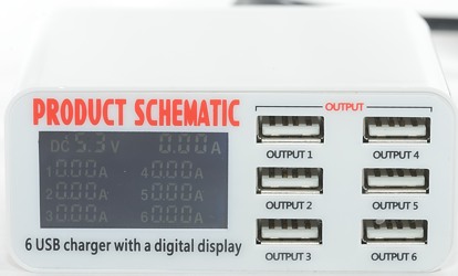
- The voltage readout on the display is fixed at 5.3V and will not show the real output voltage.
- All Usb output is coded as Apple 1A
- All outputs are in parallel, except for a 0.1ohm current sense resistor in 0V for each.
- Weight: 246g
- Size: 88.3x85.3x37.2mm
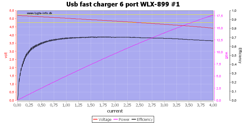
Each output is rated for 3.5A, it can deliver that and more, i.e. no individual port over load protection.
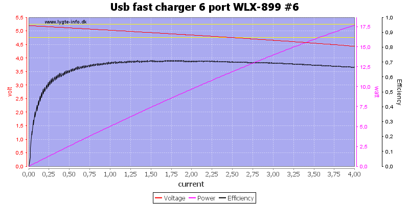
Another output looks exactly the same.
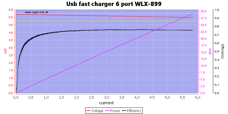
The total output is rated at 6A, there is some problems delivering that, it is more like 5.8A
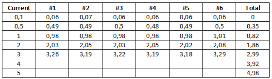
I tested the current readout, it is fairly precise from 0.5A up to 2A on a port, but at 3A it is not very precise.
The total output is done with all the port in parallel and then drawing the current. It looks like it sums the readings from the individual channels and because the channels it not very precise below 0.5A, the result first get precise when all channels is up to 0.5A, i.e. 3A total. If I had just loaded a few channels with more than 0.5A current it would also be precise.
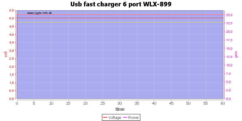
I did the one hour test at 5A and the charger could handle that.
The temperature photos below are taken between 30 minutes and 60 minutes into the one hour test.
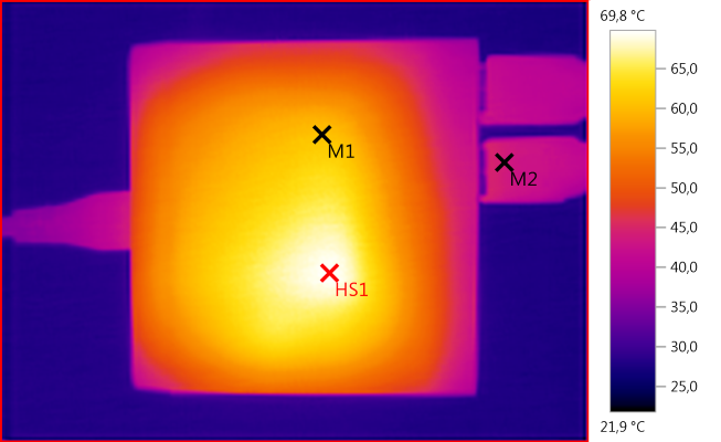
M1: 60,7°C, M2: 43,9°C, HS1: 69,8°C
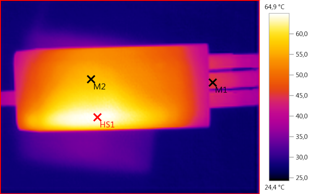
M1: 45,3°C, M2: 56,7°C, HS1: 64,9°C
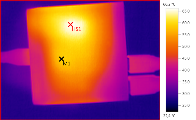
M1: 58,7°C, HS1: 66,2°C
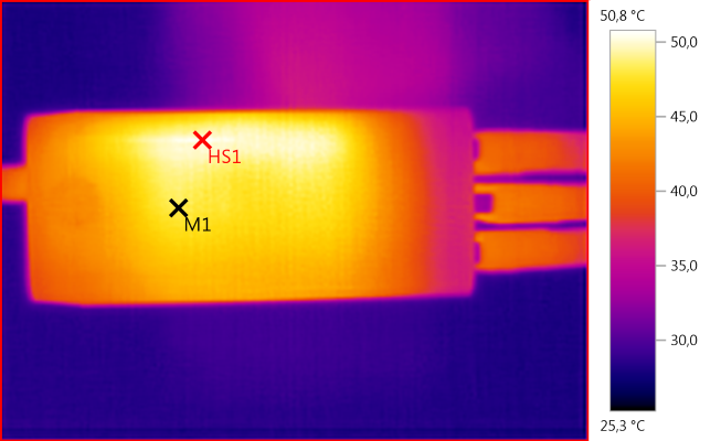
M1: 48,2°C, HS1: 50,8°C
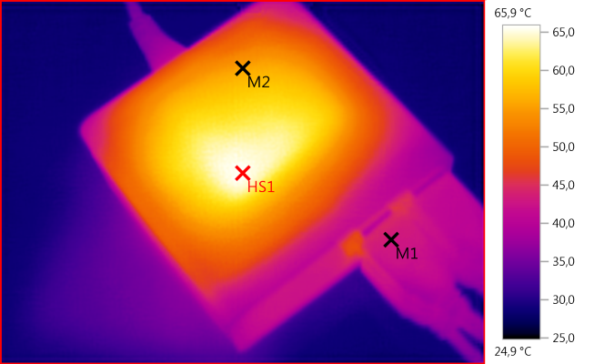
M1: 43,1°C, M2: 55,9°C, HS1: 65,9°C
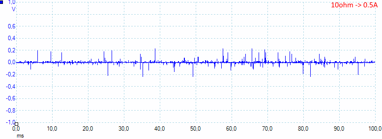
Noise at 0.5A load is: 17mV rms and 622mVpp.
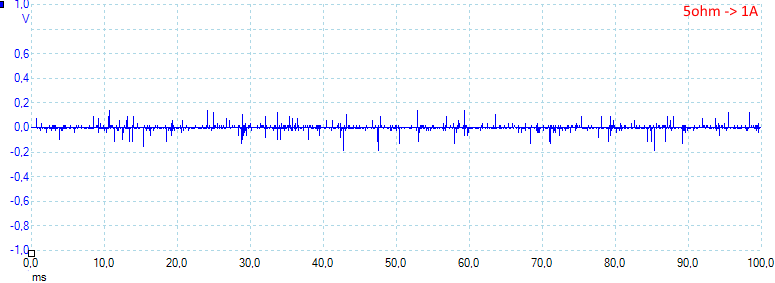
Noise at 1A load is: 14mV rms and 498mVpp.
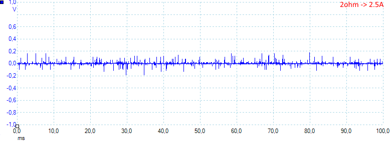
Noise at 2.5A load is: 17mV rms and 551mVpp.
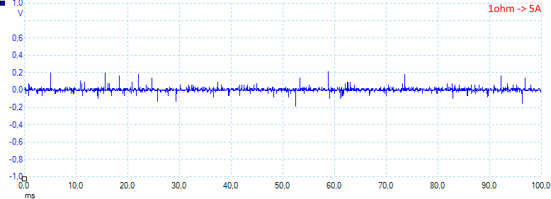
Noise at full load is: 15mV rms and 512mVpp.
Tear down
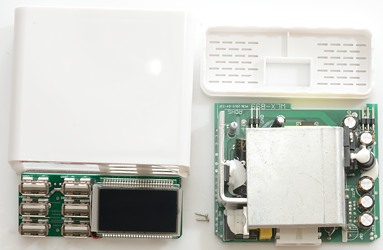
Mounting the back of the box in my vice I could easily break it off, the display and usb connectors required two screws inside the box.
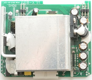
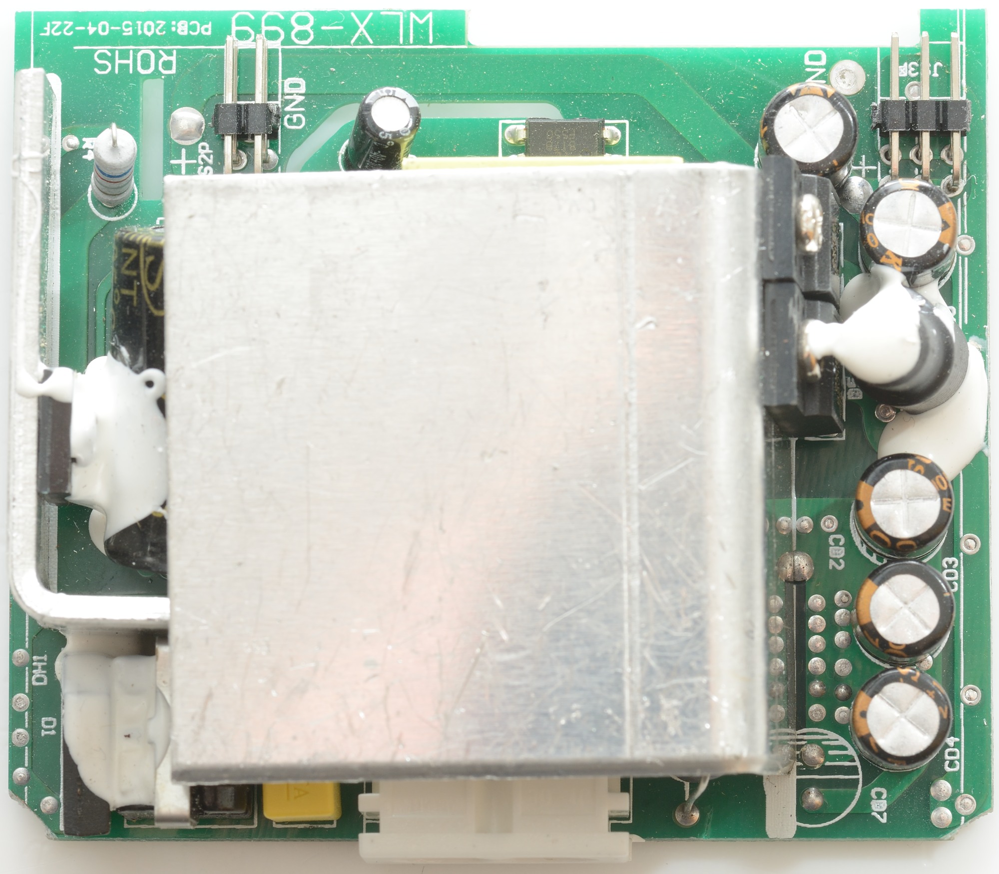
The circuit board has a large heatsink, it is used for the two rectifier diodes.
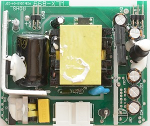
But lets look at the mains side, first there is a fuse and on the other side of the mains connectors is a common mode coil and the bridge rectifier. The small heatsink is for the mains switcher transistor.
On one side of the fairly large transformer is the opto feedback on the other side the safety capacitor. Between the 5 output capacitors is an inductor. The two connectors connect to the front panel, all signals are power: 5 gnd and 5 Vcc pins.

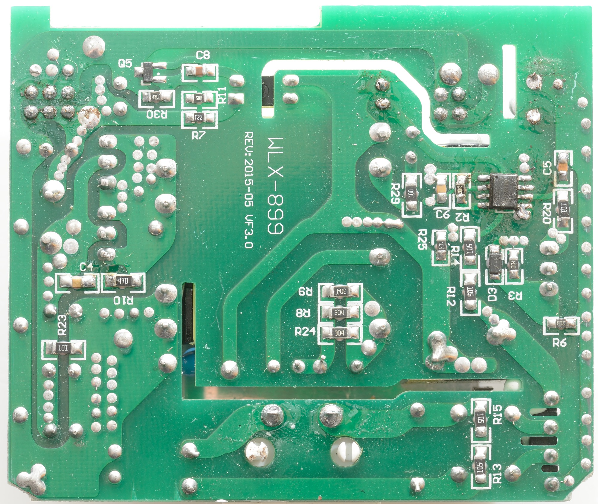
On this side of the circuit board is the mains switcher controller, the chip marked Q5 (marked 431) is the output voltage reference.

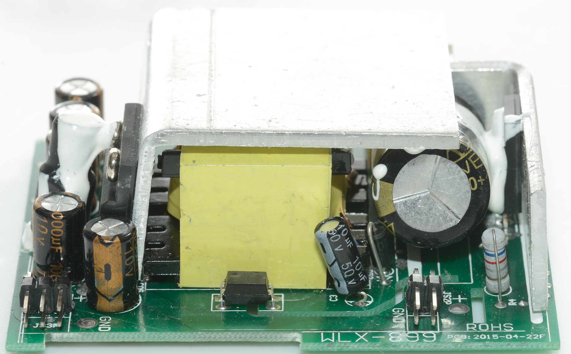
On the first picture the two rectifier diodes can be seen with an inductor in front, on the next picture the opto coupler can be seen in front of the transformer.
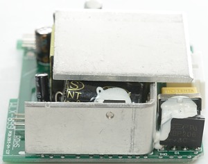
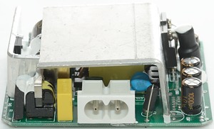
On the first picture the bridge rectifier can be seen beside the heatsink, on the second picture the common mode coil can be seen between the bridge rectifier and the yellow capacitor. The fuse is placed between the mains connector and the big heatsink.
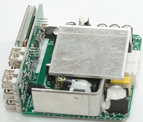
A view from above with the display/output connected to the power supply.

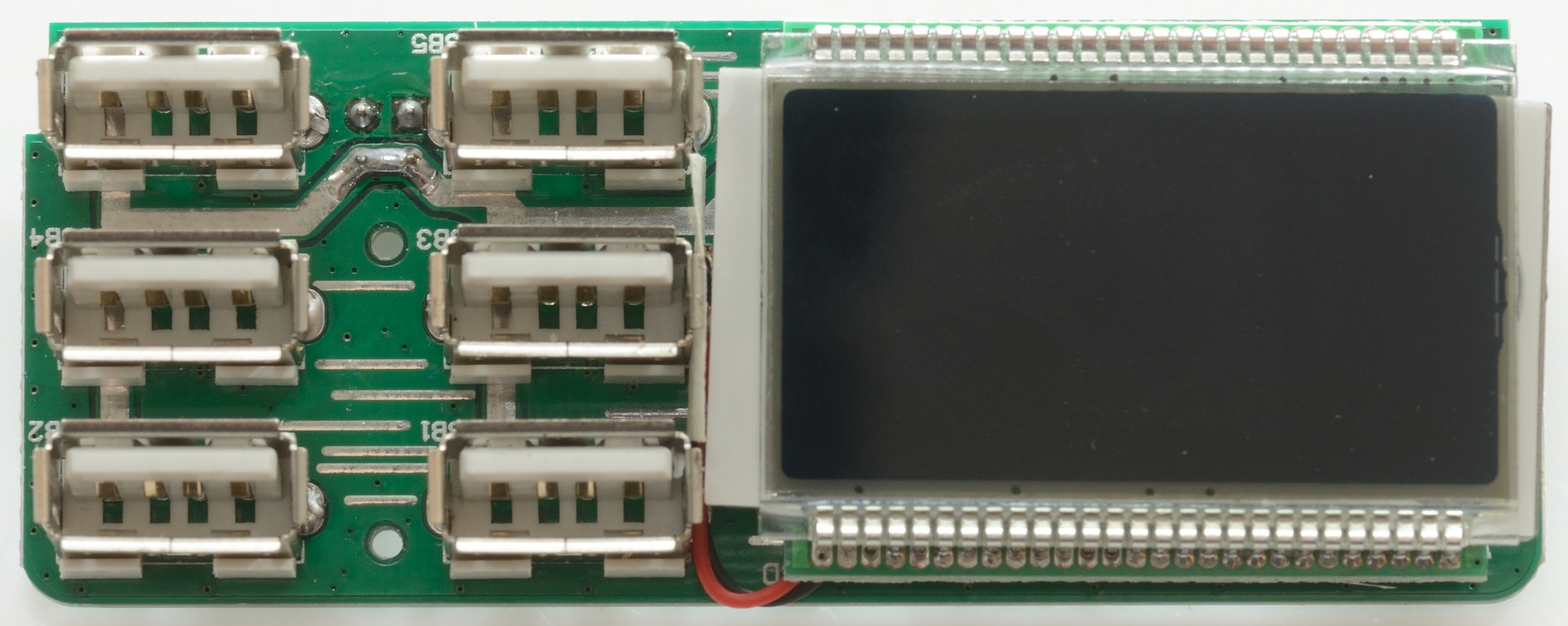
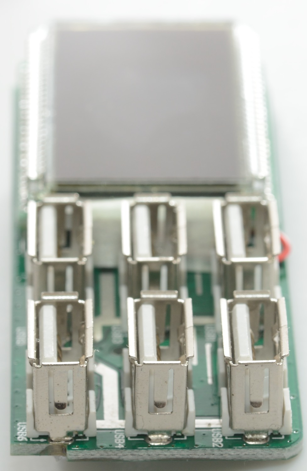
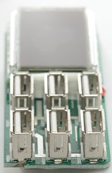
On the display/output circuit board the front has the usb connectors and the display.

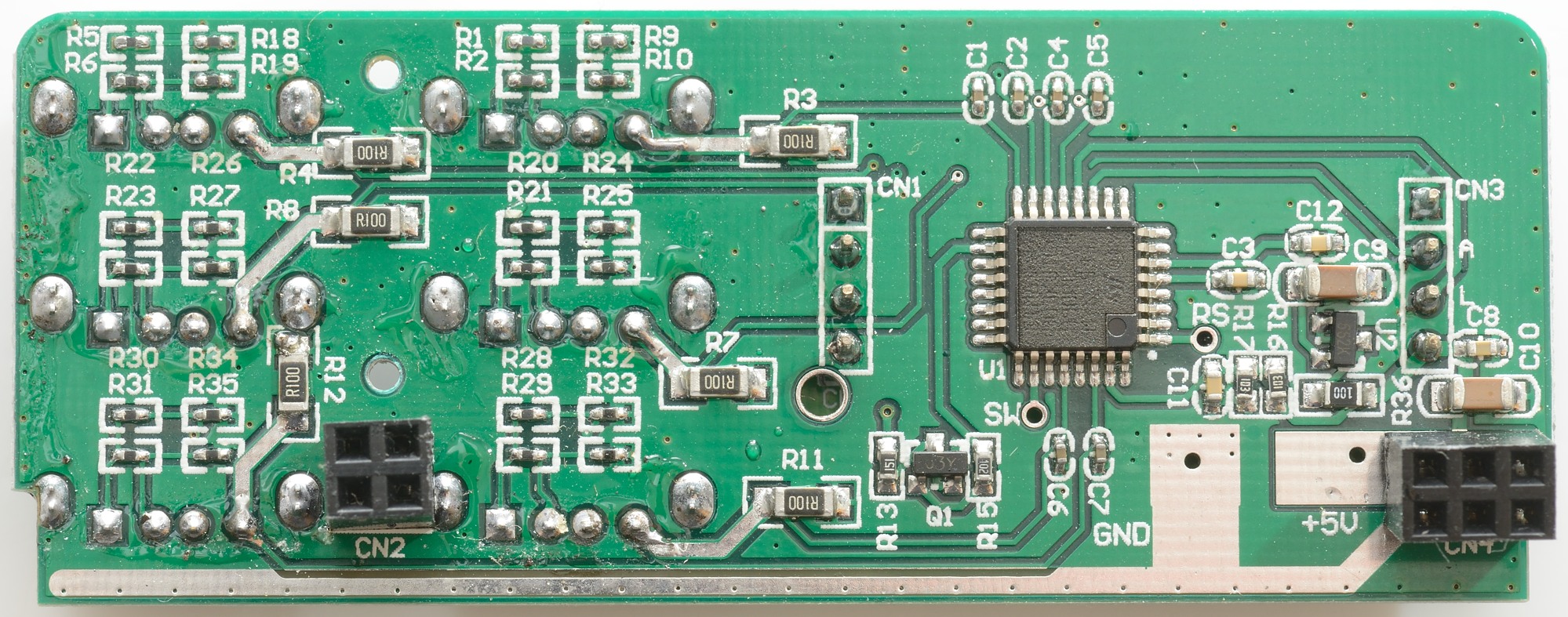
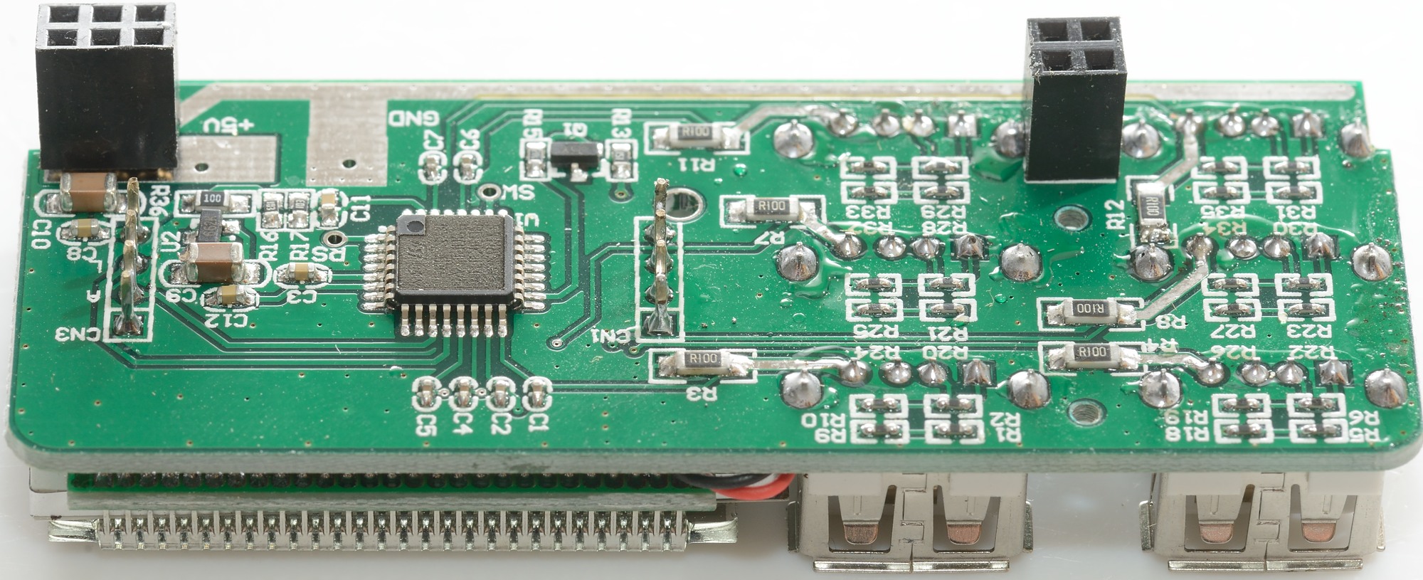
On the back is the coding for each connector, it is done with very small resistors. The 6 R100 resistors are used to measure current. The square chip do all the measuring and displays it. CN1 and CN3 is the connections to the display.
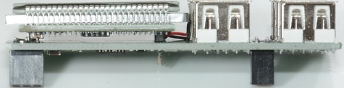
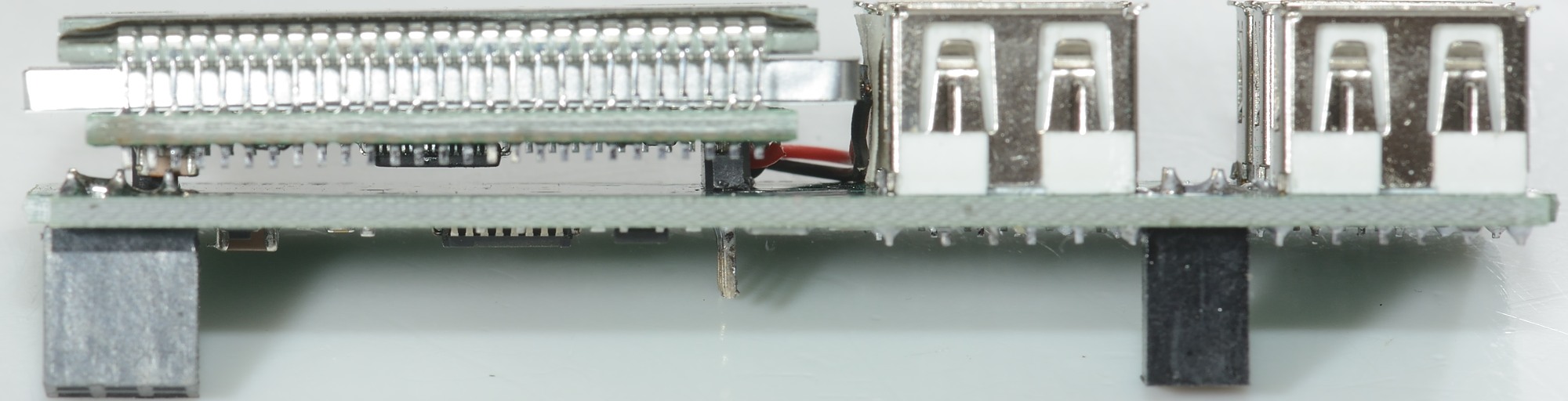
A look from the side, the display is mounted on another circuit board with a controller chip, i.e. the data from the measuring processor to the display controller is a serial bus that only requires a few pins

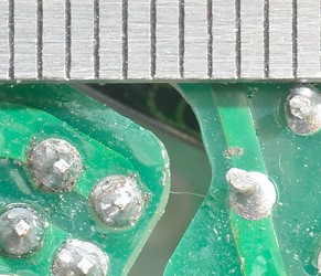
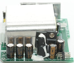
All of the above may look fine, but there is a problem with safety distances. When the board has a slot the required distance is only 4mm, here it is more like 3mm.
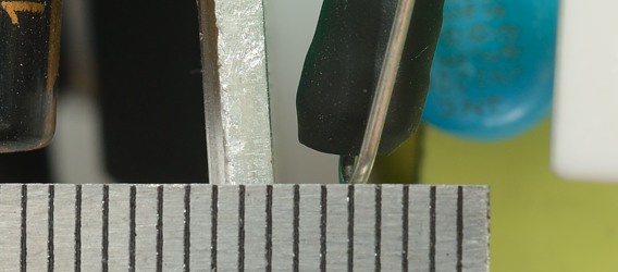
The required distance through air is also 4mm, but from the mains fuse to the rectifier heatsink there is only about 3mm and either may move if the charger is dropped.
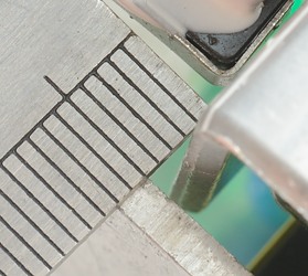
The distance between rectifier heatsink and switcher transistor heatsink is also about 3mm and again they may move if the charger is dropped.
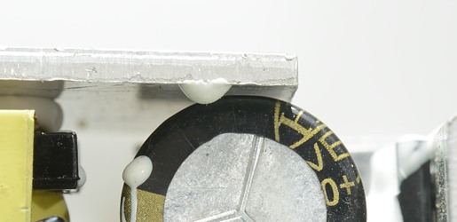
The isolation around a capacitor is not safety rated, but the input capacitor is just about touching the rectifier heatsink.
The charger passed the 2500 volt test, but failed the 5000 volt test
Conclusion
Power for a 6 port charge is a bit low, all output coded as Apple 1A is not very useful for a charger that is supposed to deliver up to 3.5A on one connector. The current measuring is a nice feature, but can be done with an external usb meter.
Generally the safety rather doubtful and I will not recommend using it in 230VAC countries.
Notes
Index of all tested USB power supplies/chargers
Read more about how I test USB power supplies/charger