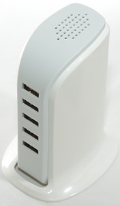
30W 5 port
Official specifications:
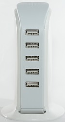
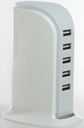
- 5 USB outputs
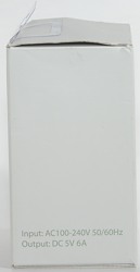
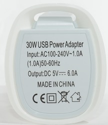
- Input: 100 - 240V 1.0A 50 - 60Hz
- Output: DC 5V 6A
- Transfer efficiency: More than 80 percent
- Cable length: 130cm
- Color: White
I got it from gearbest sku:130867901
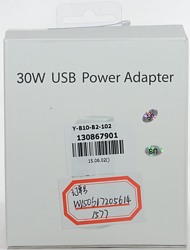
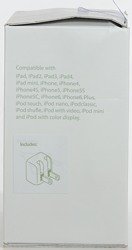
I got this charger in a cardboard box.
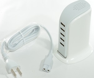
The box only included the charger and a main lead with US plug.
Measurements
- Power consumption when unloaded is 0.22 watt
- All outputs are in parallel.
- USB Output top is coded as USB charger (DCP)
- USB Output #2 is coded as USB charger (DCP)
- USB Output #3 is coded as Apple 0.5A
- USB Output #4 is coded as Samsung
- USB Output bottom is coded as Apple 2.1A
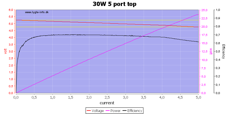
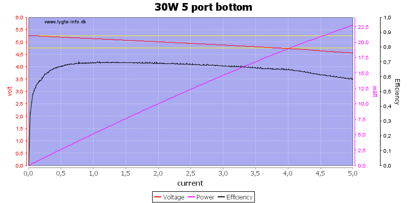
Output voltage is fine, but there is no individual port overload protection. The specification about 80% efficiency is rather optimistic, 70% would be more correct.
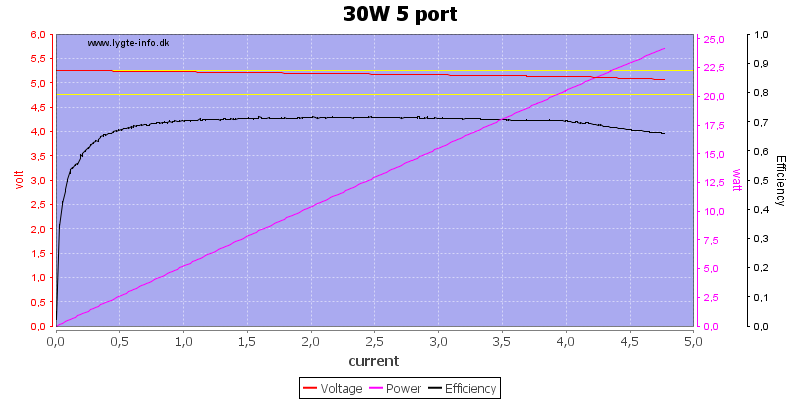
For some reason the overload protection tripped when I used all ports in parallel.
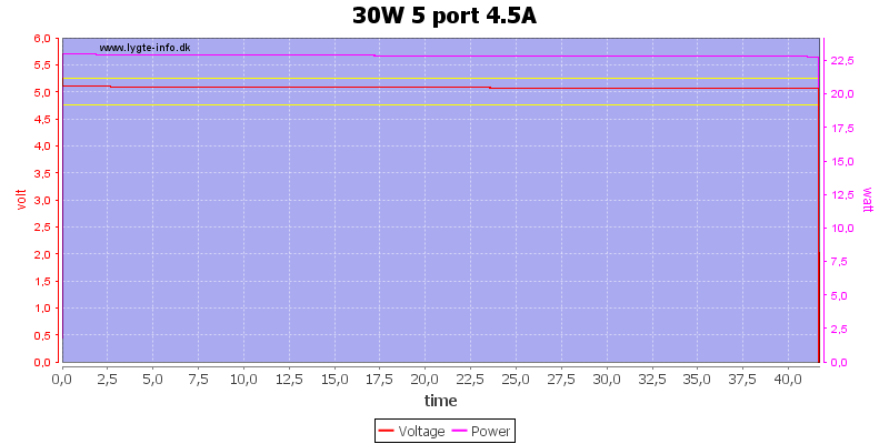
I decided to do a one hour run at 4.5A, but after about 45 minutes it quit.
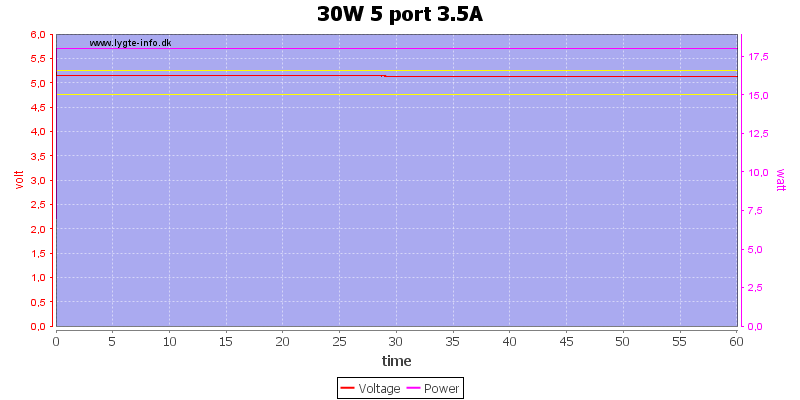
For some reason I could not get it to run at 4A, instead I did a 3.5A run and it worked for one hour.
The temperature photos below are taken between 30 minutes and 60 minutes into the one hour test at 3.5A.
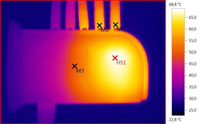
M1: 60,9°C, M2: 61,0°C, M3: 50,7°C, HS1: 68,8°C
HS1 must be the single rectifier diode.
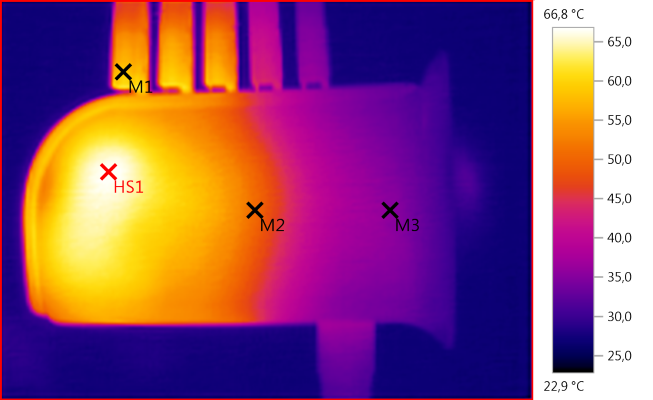
M1: 58,7°C, M2: 50,7°C, M3: 35,3°C, HS1: 66,8°C
Again HS1 must be the single rectifier diode.
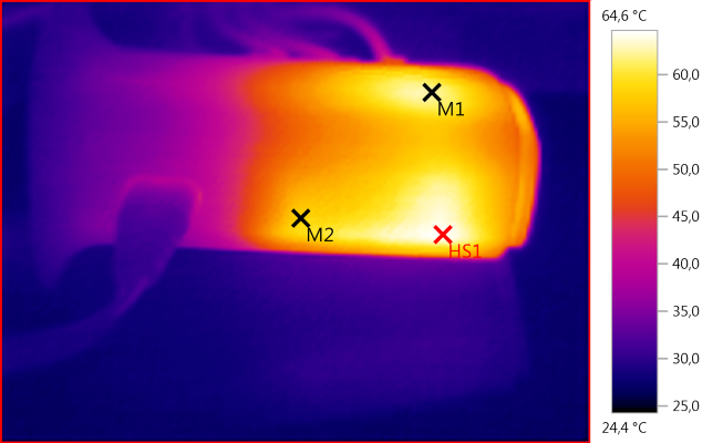
M1: 62,5°C, M2: 58,2°C, HS1: 64,6°C
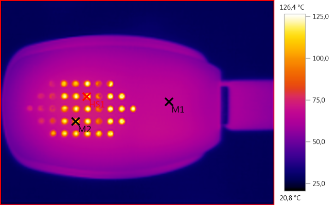
M1: 66,9°C, M2: 119,8°C, HS1: 126,4°C
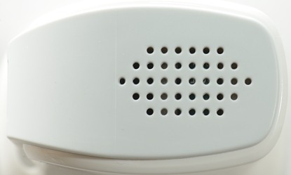
The outside temperature is acceptable at 3.5A, but when looking through the cooling holes some very hot parts can be detected. This is the heatsink for the rectifier diode, the diode will be even hotter. This high temperature is bad for the capacitors mounted just besides the heatsink.
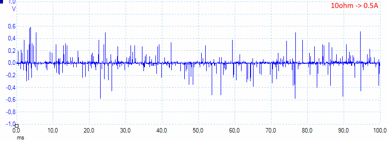
At 0.5A the noise is 41mV rms and 1350mVpp, that is a lot of peak noise.
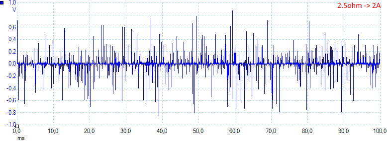
At 2.5A the noise is 80mV rms and 2000mVpp
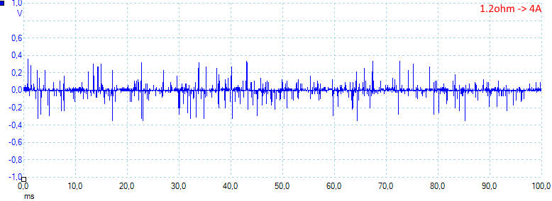
At 4A the noise is 40mV rms and 980mVpp, at full load the noise is a bit lower.
Tear down
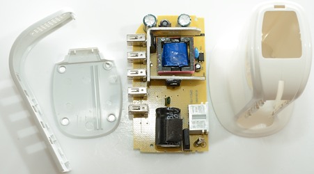
It was fairly easy to open in my vice, but it had been even easier if I had removed the screws under the label!
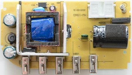
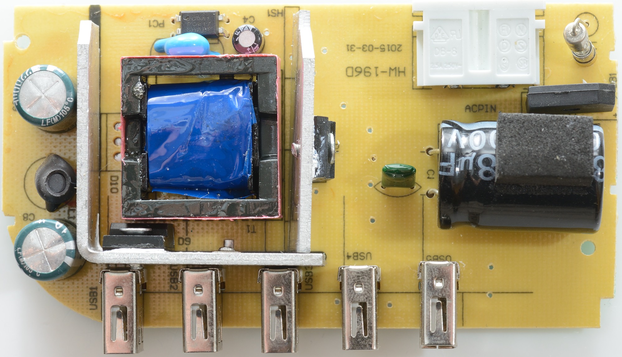
It looks fairly simple, on the mains side there is a fuse, a bridge rectifier and a mains switcher transistor that is sharing heatsink with the rectifier diode. There is also an empty space for one more rectifier diode. It has an inductor on the low voltage side and opto feedback and a safety capacitor.
I do not like the shared heatsink!
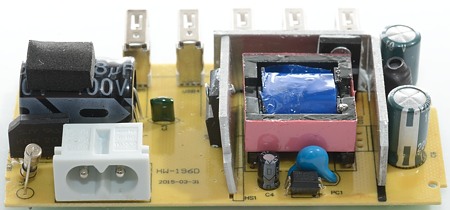
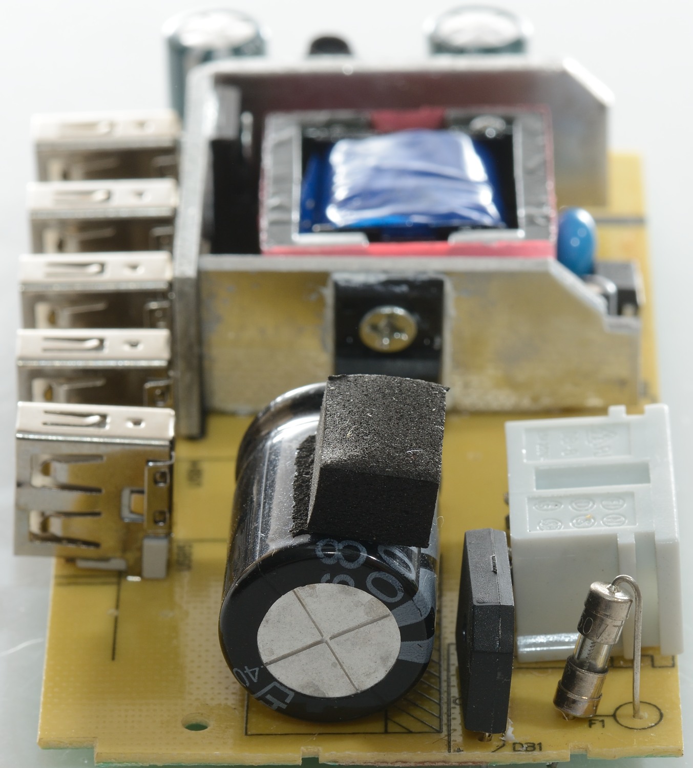
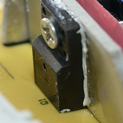
Here is a better view of the fuse, the opto feedback and the safety capacitor.

Between the two capacitors the inductors can be seen. From the mains side the fuse and the bridge rectifier can be seen.
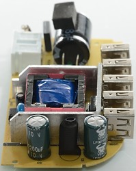
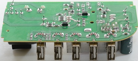
This side only has the USB connectors.
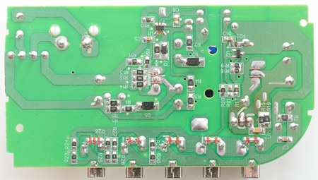
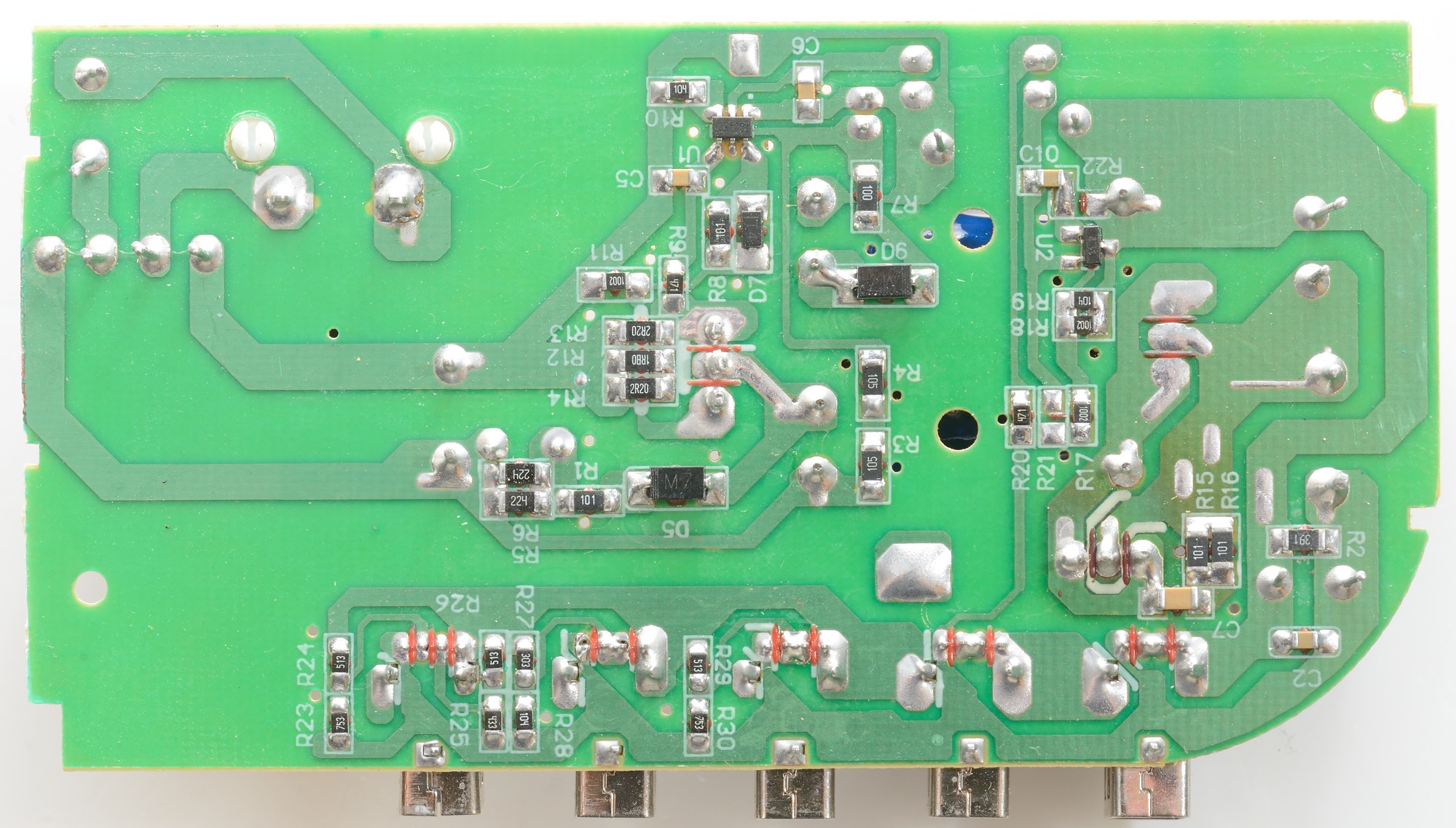
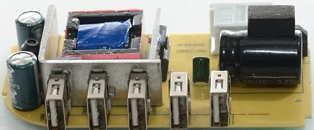
From this side the mains switcher (U1) and the feed back controller (U2) can be seen. Between the usb connectors are some resistors for coding.
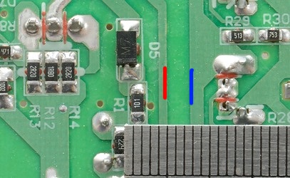
The distance between mains and low volt side is about 2.5mm on the circuit board. From the legs of the mains switch transistor to the heatsink is minimum 2.55mm (Datasheet value). Both values are way below the required distance for 230VAC and CE marking.
The charger passed an isolation test with 2500 volt, but failed a 5000 volt test, this makes the charger acceptable for 120VAC usage, but doubtful for 230VAC usage.
Conclusion
The output power is not the rated 6A, but more like 4A and only for a short time. It gets very hot and output has a lot of electric noise.
For US/120VAC it might work, but it is marked 240VAC and that is NOT safe.
Notes
The usb power supply was supplied by gearbest for a review.
Index of all tested USB power supplies/chargers
Read more about how I test USB power supplies/charger