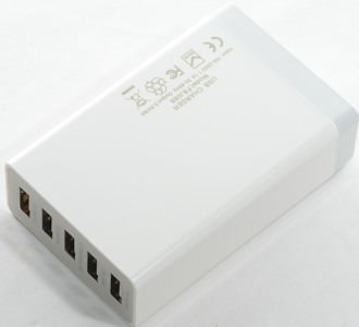
USBpower 40W 5V 8A 5 Port F8J088
Official specifications:
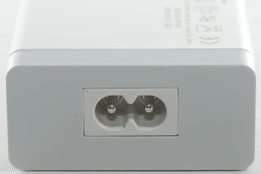
- Input: AC100-240V
- Total Maximum Output: 5V/8A
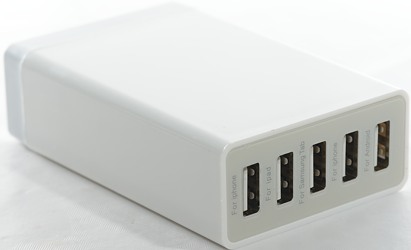
- Quantities of the charging port: 5-ports
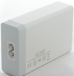
- Dimension: 91*58*26mm
- Weight: 110g
I got it from ebay dealer gocisco
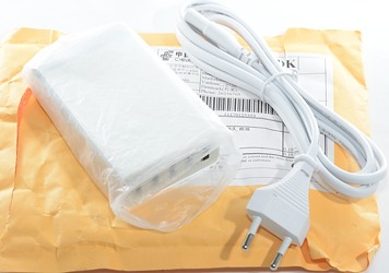
Being from ebay I got it in a envelope.
Measurements
- Unloaded power consumption is 0.2 watt
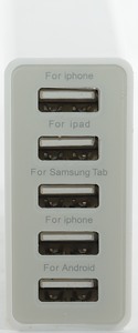
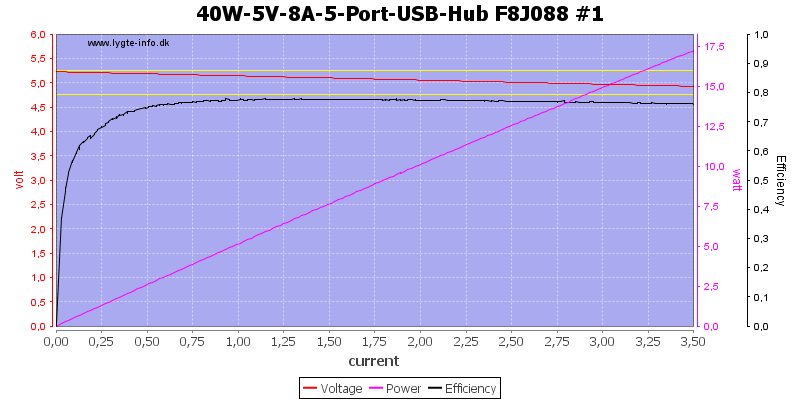
- Usb output #1 is coded as Apple 1A
- Usb output #2 is coded as Apple 2.1A
- Usb output #3 is coded as Samsung
- Usb output #4 is coded as USB charger (DCP)
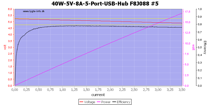
- Usb output #5 is coded as USB charger (DCP)
The ports looks the same and without individual overload protection.
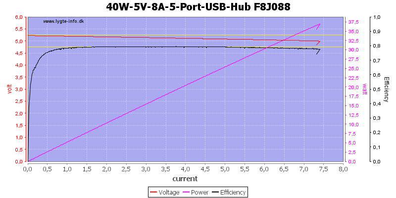
Running all ports together shows that there is a common overload protection at about 7.5A.
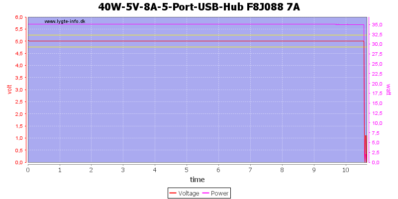
The charger is rated for 8A, but with overload protection at 7.5A that is impossible. I did first test at 7A and the charger could only maintain output for about 10 minutes before it shut down.
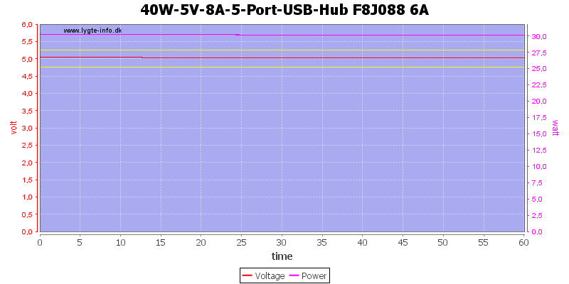
Reducing the load to 6A made it possible to run for 1 hour.
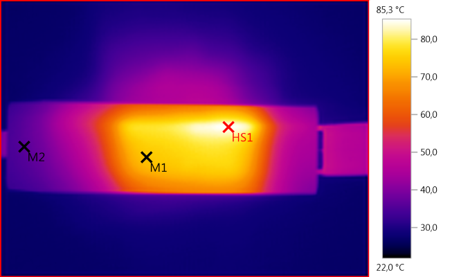
The temperature photos below are taken between 30 minutes and 60 minutes into the one hour test.
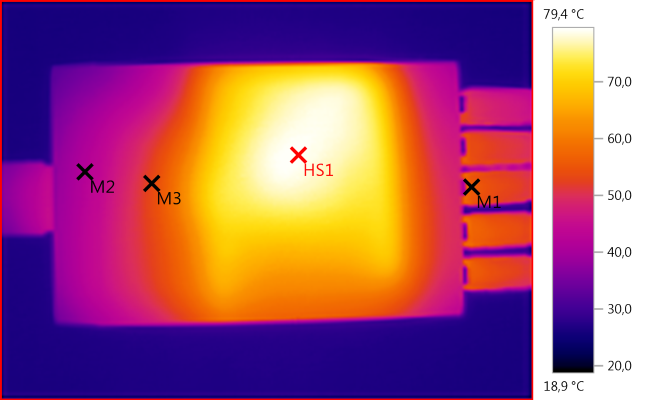
M1: 55,6°C, M2: 41,9°C, M3: 53,2°C, HS1: 79,4°C
HS1 is the transformer and the heat around it is from the heatsinks.
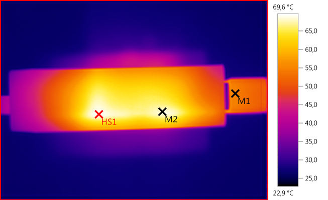
M1: 54,8°C, M2: 68,5°C, HS1: 69,6°C
HS1 and M2 is the end of the heatsinks.
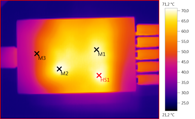
M1: 69,5°C, M2: 70,9°C, M3: 49,2°C, HS1: 71,2°C
M1: 74,0°C, M2: 36,0°C, HS1: 85,3°C
HS1 is the from the the rectifier diode.
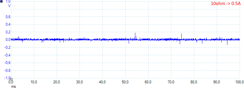
There noise is acceptable with 12mV rms and 380mVpp.
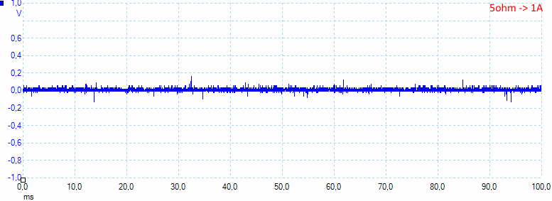
Increasing the current to 1A do increase the noise a bit 32mV rms and 450mVpp.
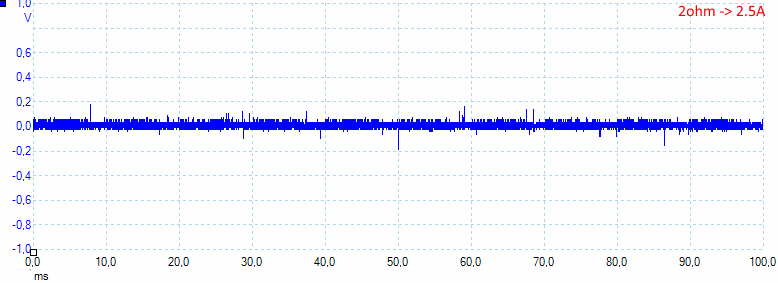
At 2.5A the noise is at the same level 28mV rms and 450mVpp.
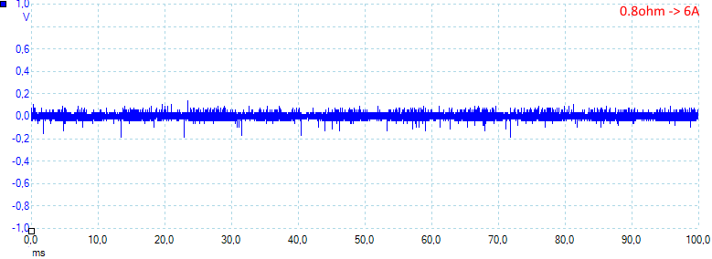
And also at near maximum load: 33mV rms and 445mVpp.
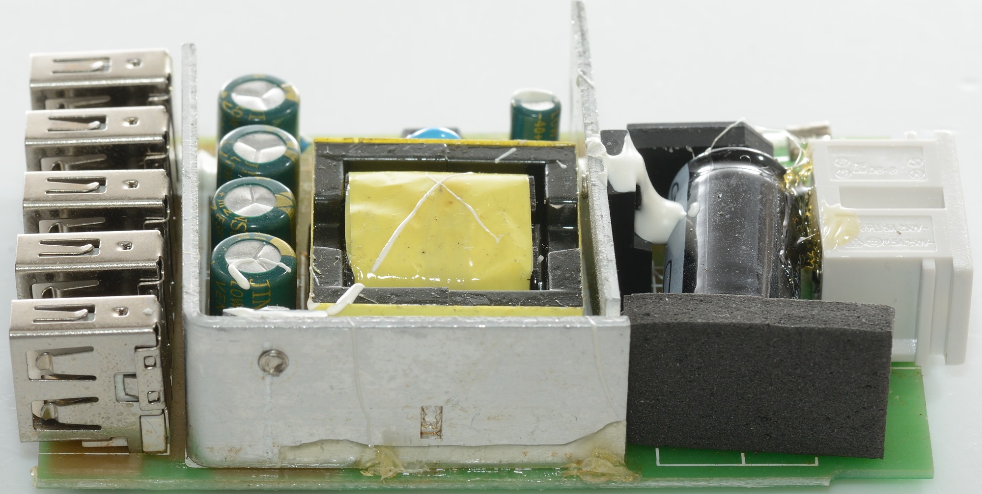
Tear down
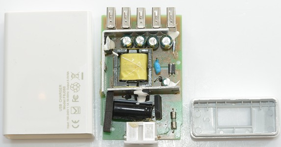
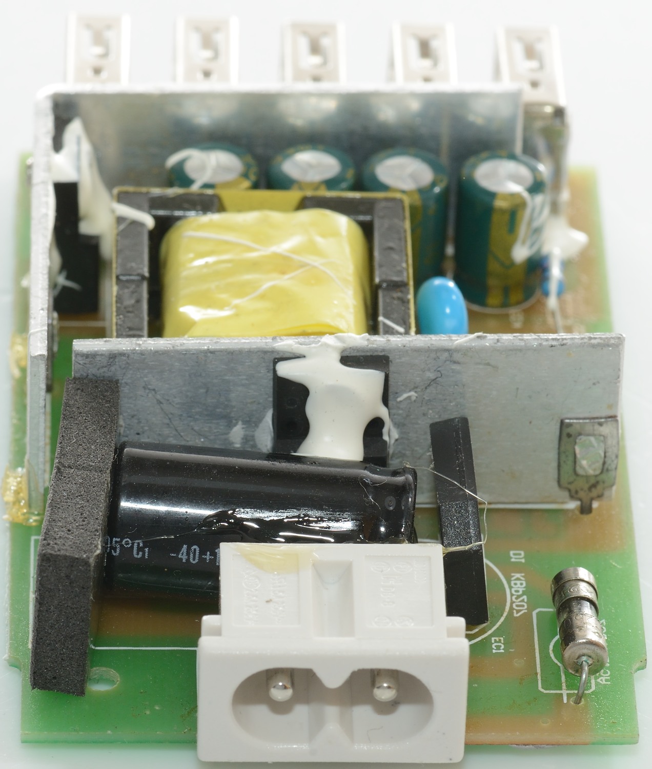
Mounting the dark part in my vice and hitting the white part with a mallet did open it without any damage.

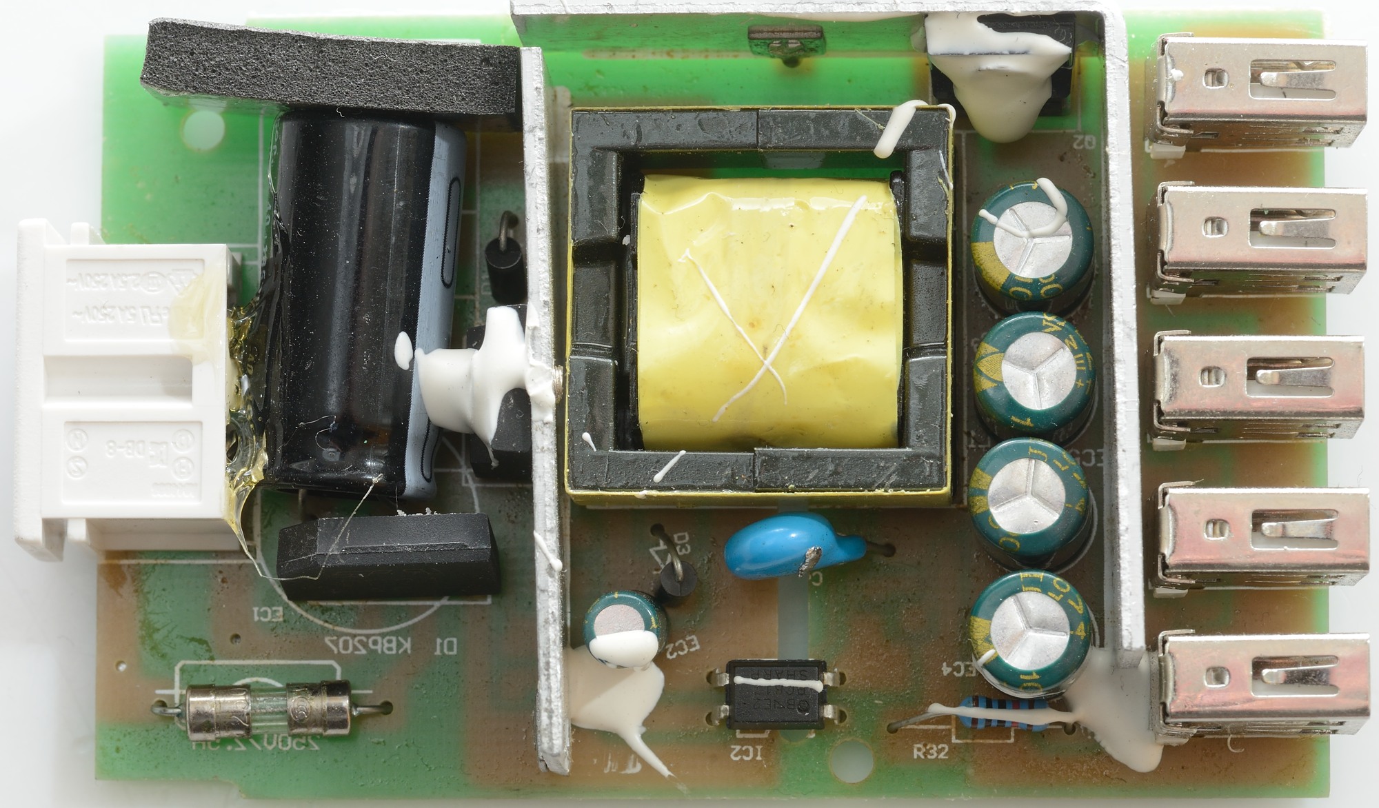
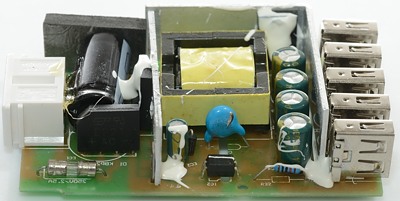
On this side of the circuit board is mains input fuse and a bridge rectifier. The mains switcher transistor is moundted on a heatsink.
There is a opto coupler and a safety capacitor between the mains and the low volt side.
On the low volt side there is a rectifier diode with a large heatsink.
But there is no noise filtering neither on the mains input or on the usb outputs (No common mode coils or inductors).

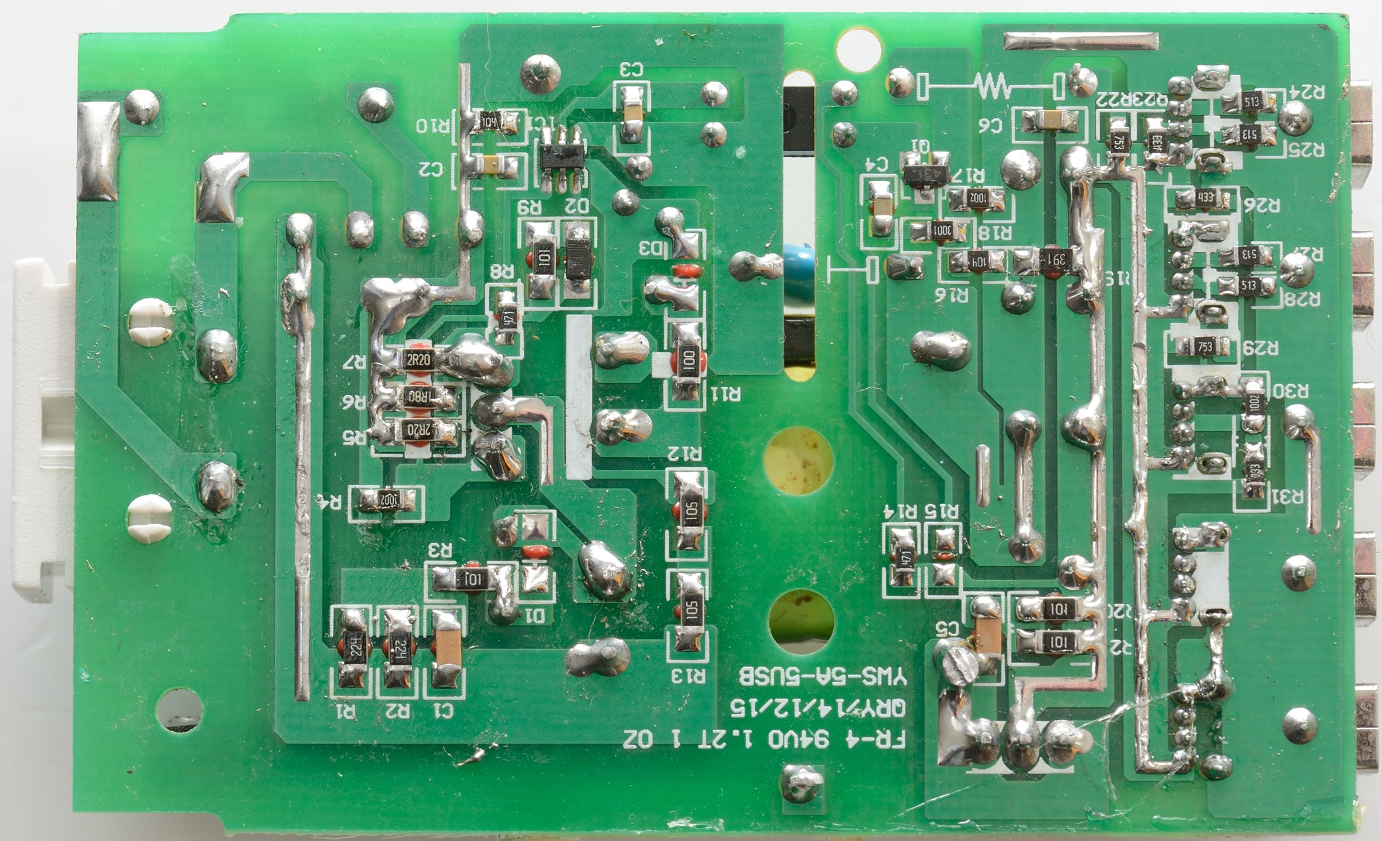
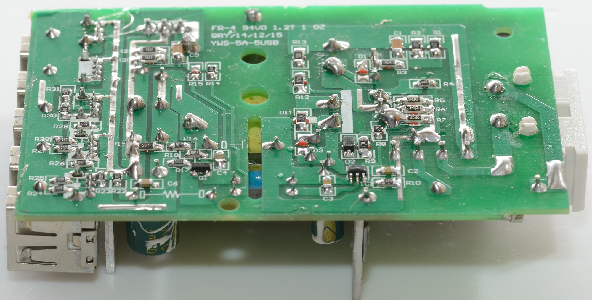
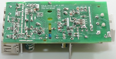
On the bottowm the mains switcher controller can be found (IC1). The usb ports has a couple of coding resistors.
The feedback circuit do not use a IC, but only a transistor (Q1).
Somebody left a solder blob on the safety capacitor..

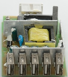

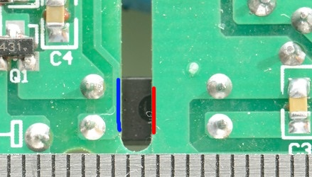
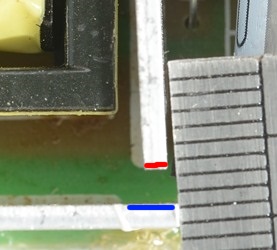
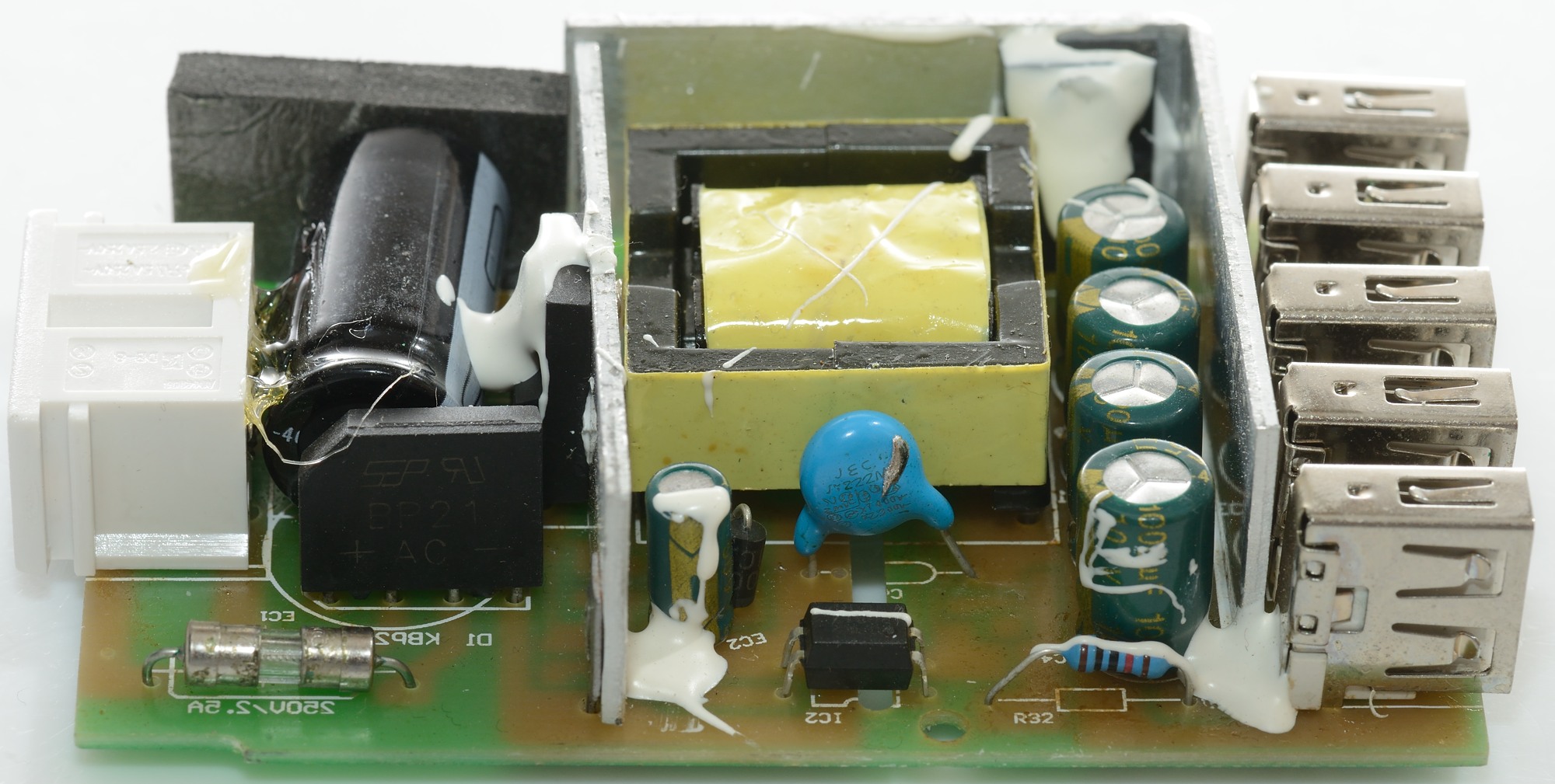
When there is a air-gab the distance between mains and low volt side can be down to 4mm, here it is 2mm and a spark jumped accross it when I tested with 5000 volt. The two heatsinks are also too close.
The charger passed an isolation test with 2500 volt, but failed a 5000 volt test, this makes the charger acceptable for 120VAC usage, but doubtful for 230VAC usage.
Conclusion
At first glance this charger may look like many other 5 ports chargers, but this one is not nearly as good. Only fixed codings on the output, cannot deliver full current and worst of all it is not safe.
Notes
Index of all tested USB power supplies/chargers
Read more about how I test USB power supplies/charger