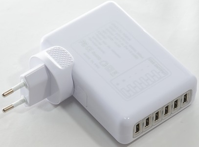
6 port 4A
Official specifications:
- Plugs: AU/EU/UK/US plug
- Input Voltage: AC 100-240V, 50/60Hz
- Output Voltage: 5.25V ± 0.25V
- Input Current: ?64mA @ 220V AC with full load
- Load regulation: -0.5%(Max)
- USB1.2.3.4: FOR IPHONE, IPAD
- USB5.6: FOR SAMSUNG
- Output current: 4A 20W
- Output Ripple:<600mV p-p
- Efficiency:>70%@220V AC
- Output plug: USB TYPE A x 6
- Over power protection: 12.50W@ 220V AC
- Short protection: Auto Recovery
- Dimension: 76.5 x 55.1 x 29.4(mm)
I got it from Ebay dealer fzeroinestore

I got this charger in a plastic bag.
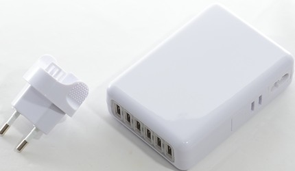
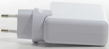
The power plug is seperate from the charger and it is possible to order it with different plugs, but not with all plugs for travel usage.

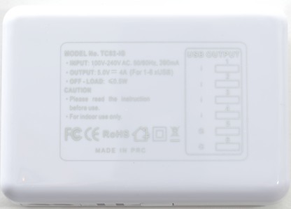
The printing is in silver and shows what the specifications, including coding of ports.
It does also say I must read the (not included) instructions.
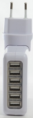
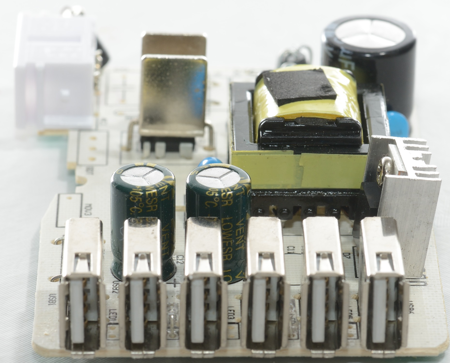
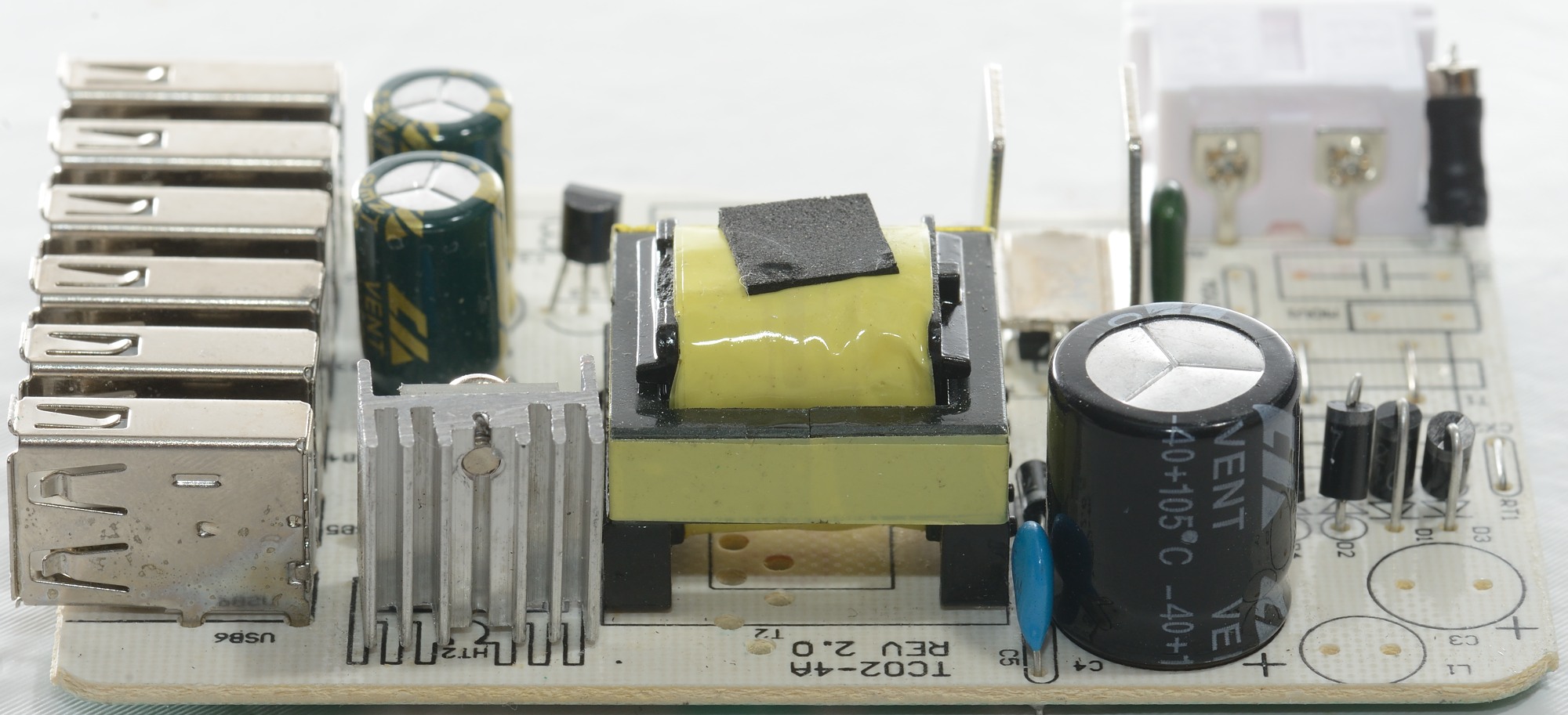
There is 6 usb outputs in one long row with blue leds between 2&3 and 4&5.
Measurements
- Power consumption when unloaded: 0.25 watt
- Usb output is coded as Apple 2.1A and Samsung tablet
- All usb outputs are in parallel.

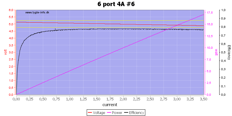
There is not much different between usb port #1 and #6, except #6 is slightly higher in voltage.
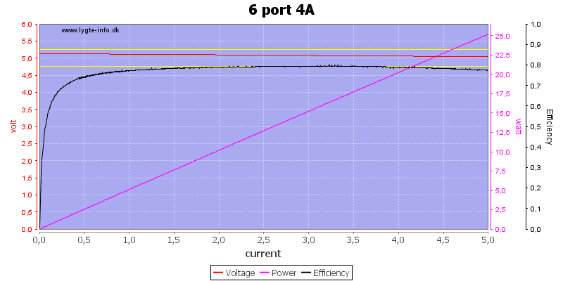
Running all outputs in parallel up to 5A works fine, but I would have liked a overload protection kicking in (I did a fast test up to 8A without seeing any protection).
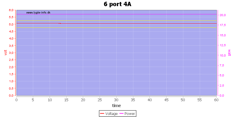
No problem running at 4A for one hour.
The temperature photos below are taken between 30 minutes and 60 minutes into the one hour test.
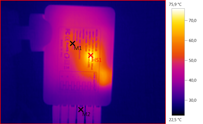
M1: 51,8°C, M2: 38,0°C, HS1: 75,9°C
HS1 is probably the transformer and the temperature is acceptable for a transformer.
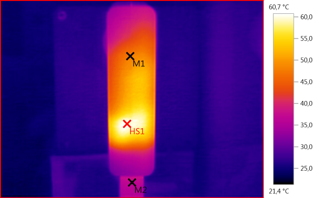
M1: 47,4°C, M2: 36,9°C, HS1: 60,7°C
HS1 must be the rectifier diode.
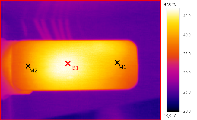
M1: 40,5°C, M2: 39,3°C, HS1: 47,0°C
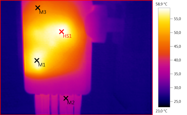
M1: 57,9°C, M2: 38,0°C, M3: 46,1°C, HS1: 58,9°C
HS1 must be the mains switcher and M1 must be the rectifier diode.
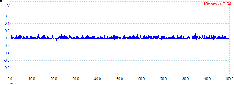
At 0.5A the noise is 19mV rms and 400mVpp. The rms noise is fairly low, but there is some spikes that gives a high peak noise.
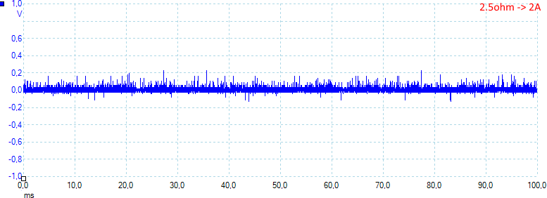
At 2A the noise is 33mV rms and 480mVpp
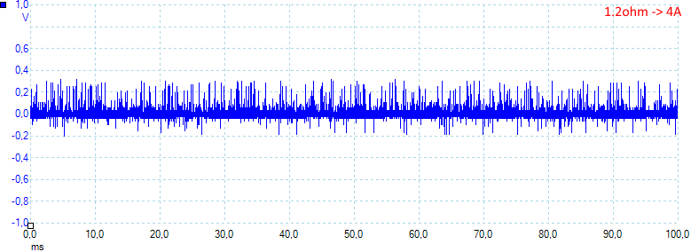
At 4A the noise is 52mV rms and 510mVpp
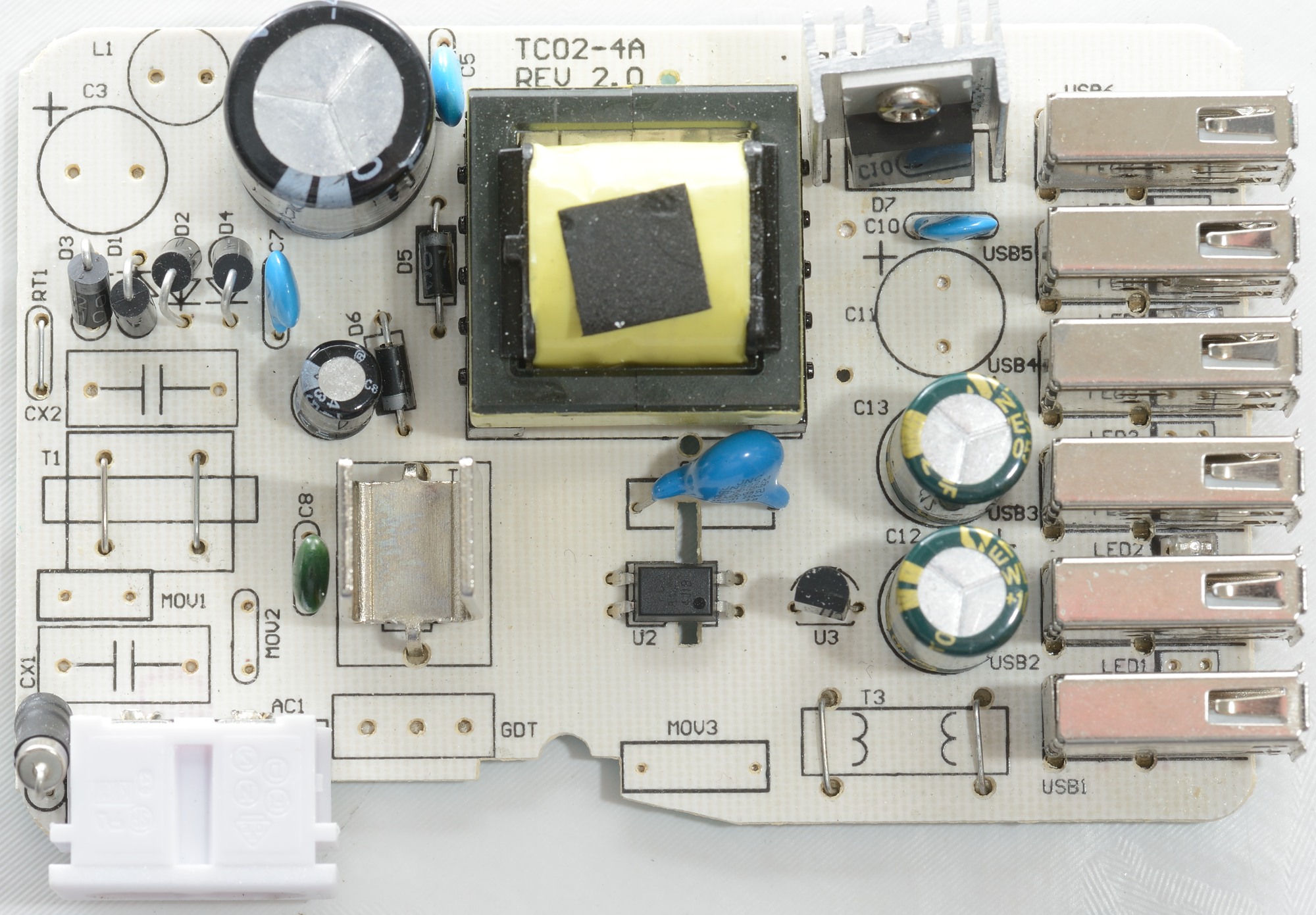
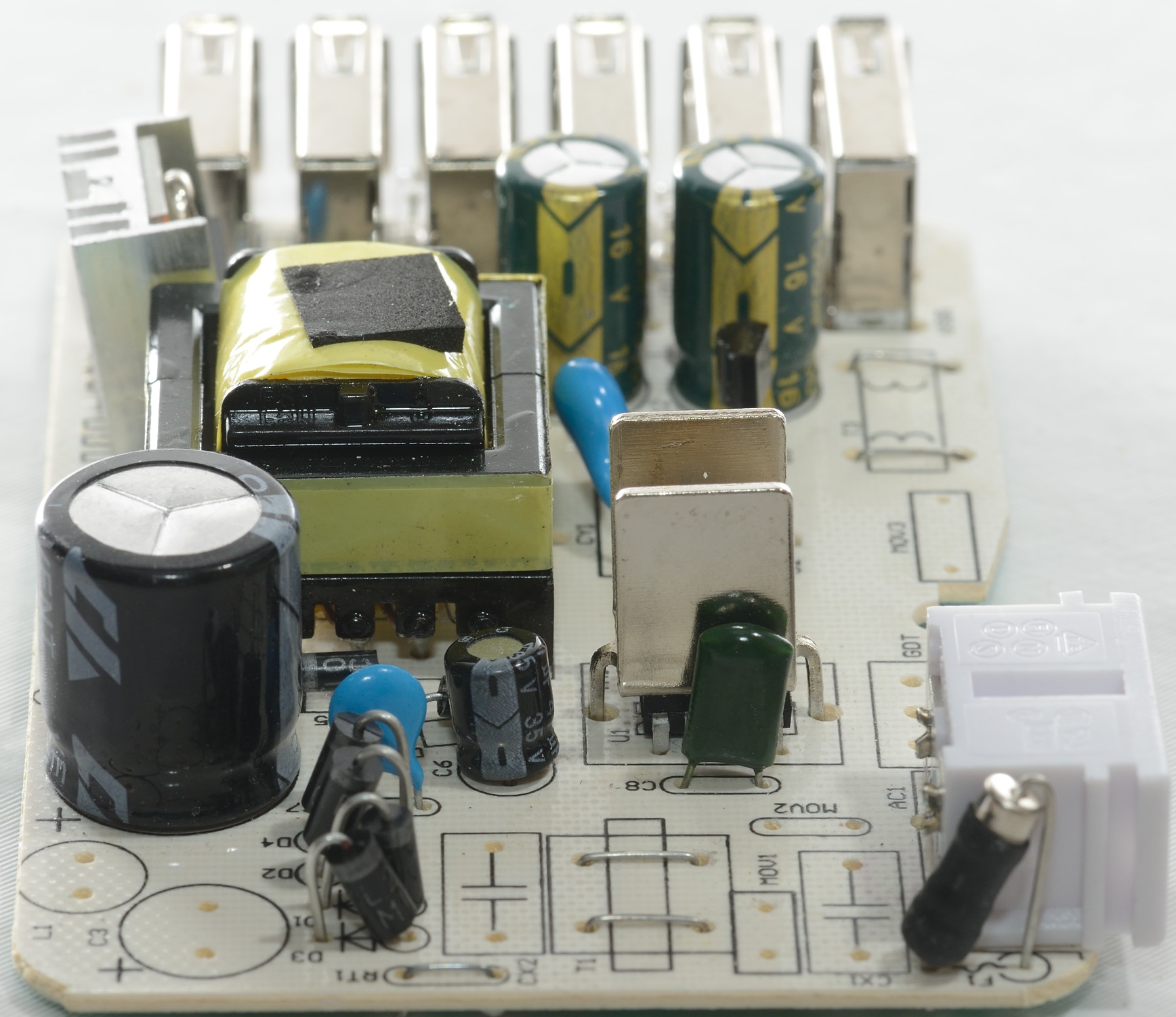
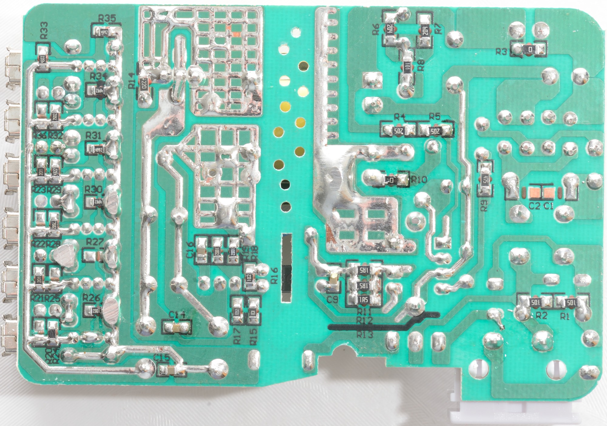
Tear down
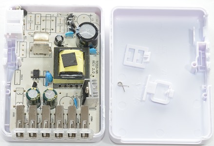

It looks like a lot of parts has been removed from the design. Most of the missing parts are designed to reduce EMC and make it less sensitive for spikes on the main.
The MOV3 part is not legal to mount, it would directly transfer spikes from the mains to the low volt side.
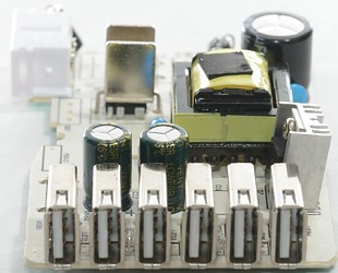
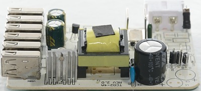
The input side has a fuse, bridge rectifier (4 diodes), capacitor and a switcher IC (Below a heatsink).
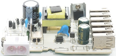
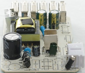
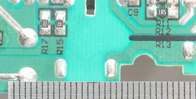
Between the usb connectors is is possible to see the leds, there is holes and print for 5 leds, but only two are mounted.
There is also missing a few parts on this side.
The power starts at usb port #6 and usb port #1 has the longest traces on the circuit board, that is the reason for the small performance difference between them.
Note: The port numbers I am using is the ones on the box, not the ones on the circuit board that are reversed.
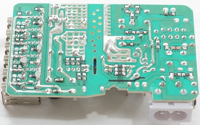
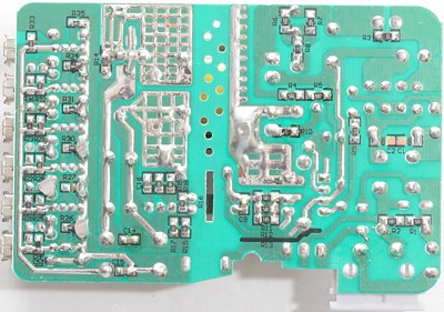
There is no issues with the isolation distance, it is fine.
Testing with 2500 volt and 5000 volt between mains and low volt side, did not show any safety problems.
Conclusion
This charger might have been a fairly good charger, before all the parts where removed from the design, without these parts I doubt it will pass the EMC part of the CE test.
The safety looks good, except the missing overload protection, both for each usb port and for the full device.
Notes
Read more about how I test USB power supplies/charger