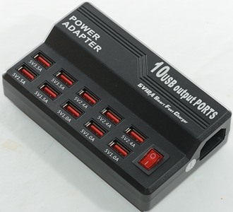
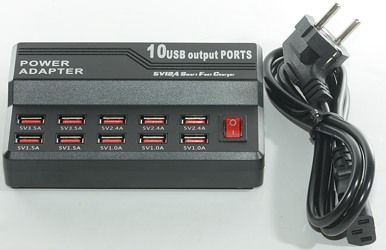
60W 10 port usb charger W-838
Official specifications:
- Plug: US/EU standard
- Support: For iPhone, for iPad, for Samsung, for BlackBerry, for Android phone
- Material: ABS
- Color: Black
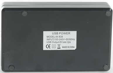
- Output: 12A
- Max Power: 60 Watts
- Input: AC 100V-240V
- Plug: EU/US/UK Supply
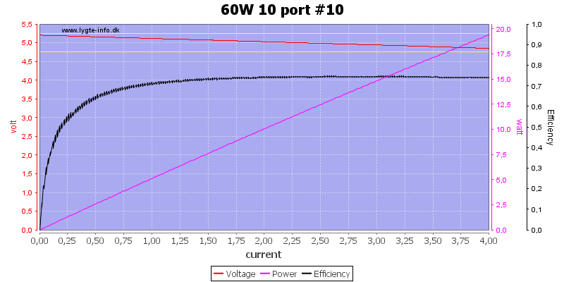
- Max output for single USB port: 5V / 3.5A
- Item size: 13.9 x 8.5 x 4.0cm / 5.5 x 3.3 x 1.6in (LxW x H)
- Item weight (cable not included): 212.0g / 7.5oz
I got it from ebay dealer: uit-tek
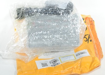
Being from ebay the shipment did not include any box.
And accessories was only a mains cable.
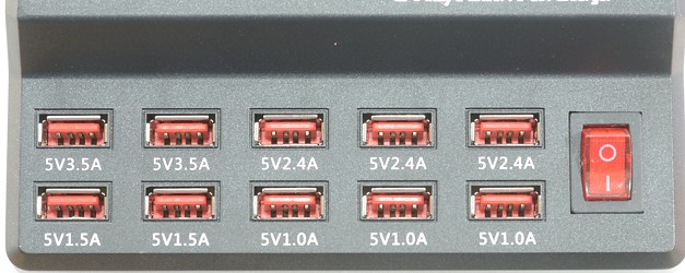
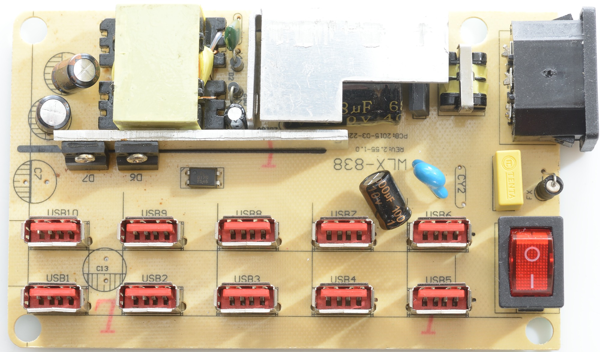
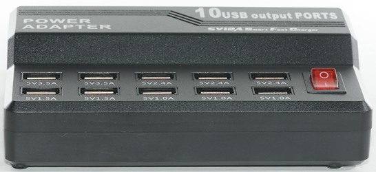
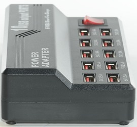
A lot of current markings on the ports, these markings are bogus and only works as decorations. All ports are exactly the same.
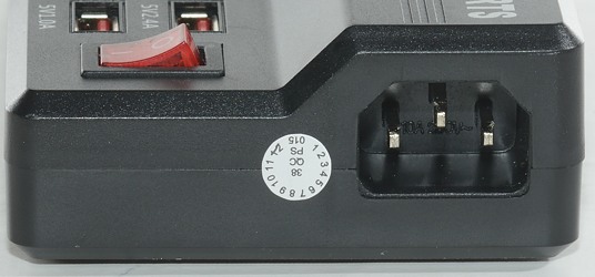
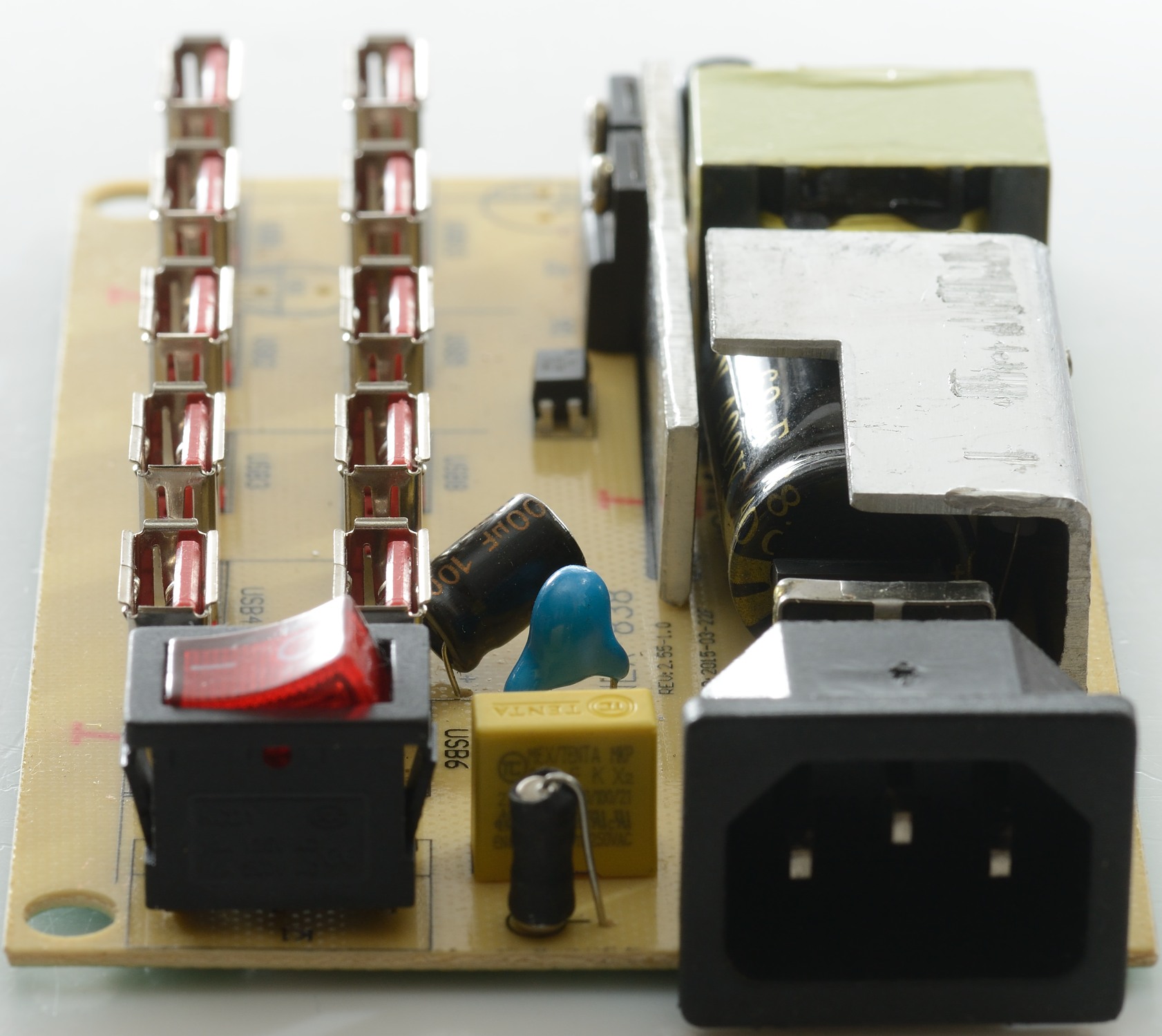
The connector for the mains lead includes a unused earth connection.
Measurements
- Power consumption when idle is 0.8 watt
- All ports are coded as Apple 2.1A
- All port are in parallel.


All port looks the same and there is no individual over current protection.
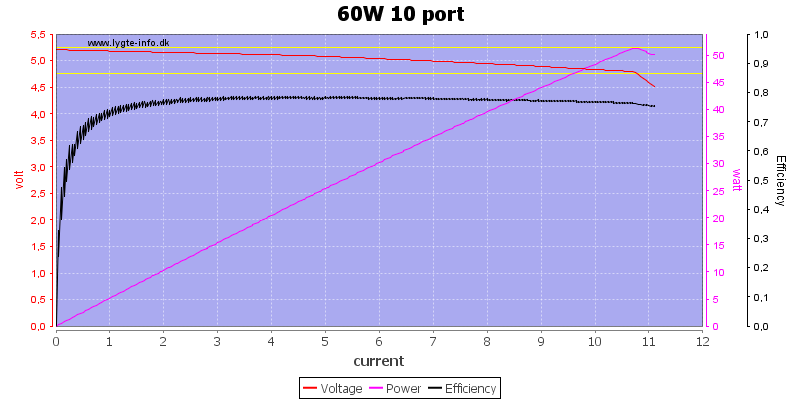
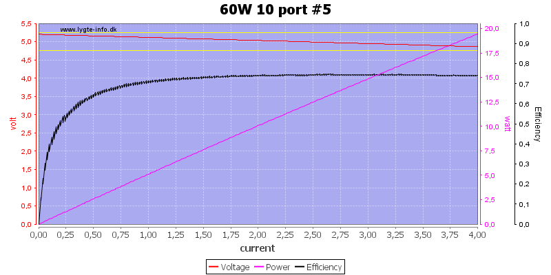
Running all port in parallel I can draw 11A, not the rated 12A, but at least it has a total over current protection.
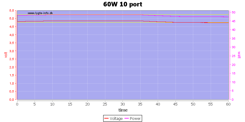
I decided to run the one hour load test at 10A and it could handle that, but I am a bit worried because the output voltage is slowly dropping.
The temperature photos below are taken between 30 minutes and 60 minutes into the one hour test.
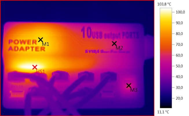
M1: 92,0°C, M2: 57,9°C, M3: 59,1°C, HS1: 103,8°C
HS1 is the two rectifier diodes and M1 is the mains transformer.
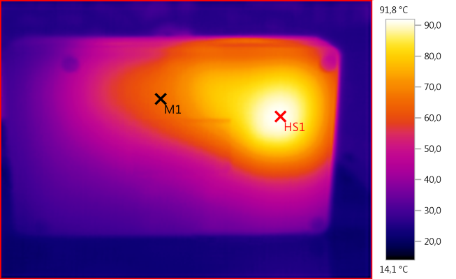
M1: 65,1°C, HS1: 91,8°C
HS1 is again the two rectifier diodes.
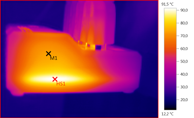
M1: 73,0°C, HS1: 91,5°C
HS1 is again the two rectifier diodes.
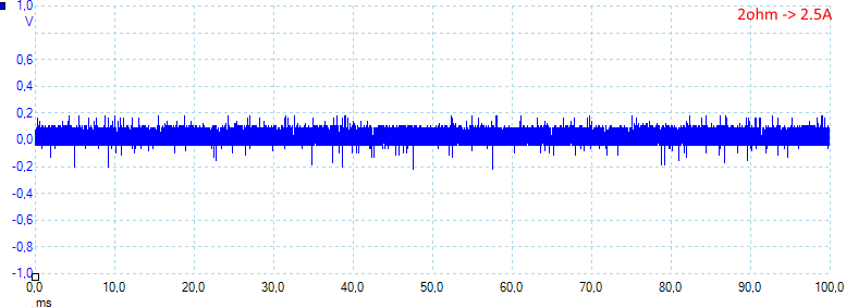
The charger has a lot of peak noise, even at low load: 26mV rms and 420mVpp
The noise increase with load: 36mV rms and 440mVpp
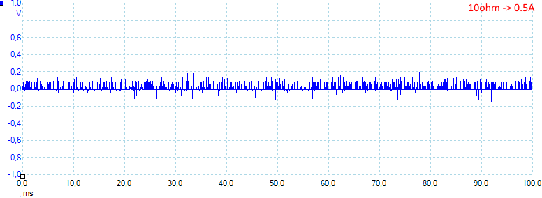
More noise: 55mV rms and 510mVpp
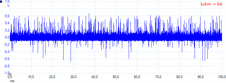
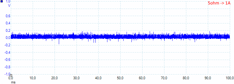
At 5A the noise is getting very bad: 115mV rms and 1380mVpp
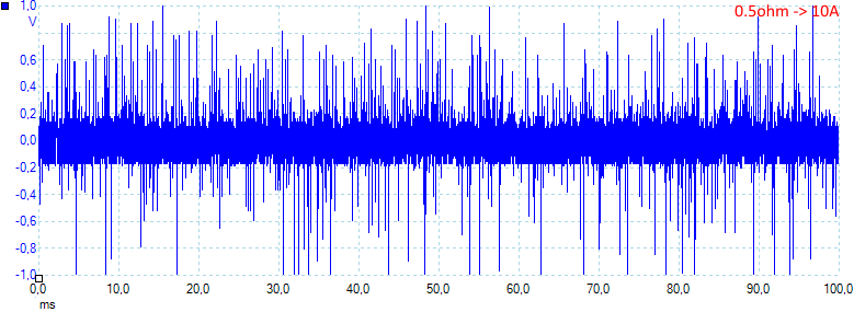
And 10A is even worse: 180mV rms and 2460mVpp
Tear down
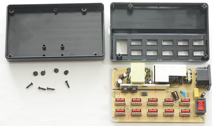
I only had to removing the four screws under the rubber feets and it was open.

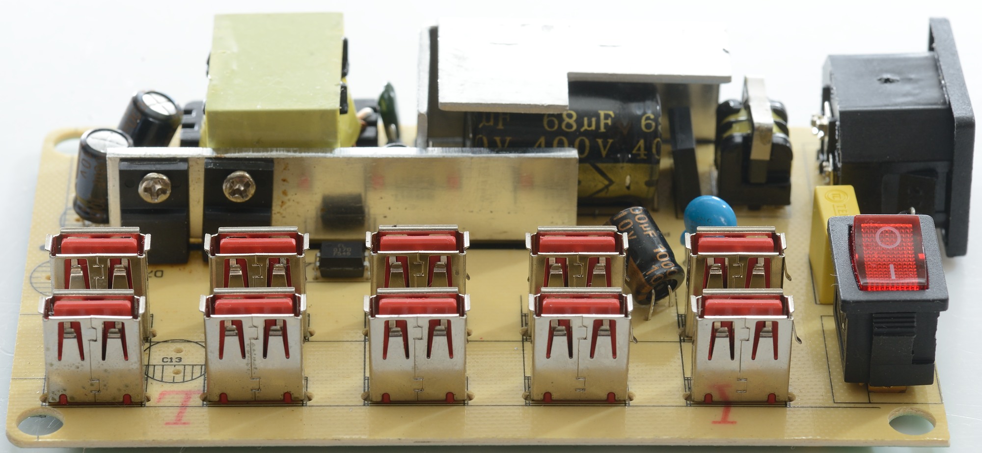
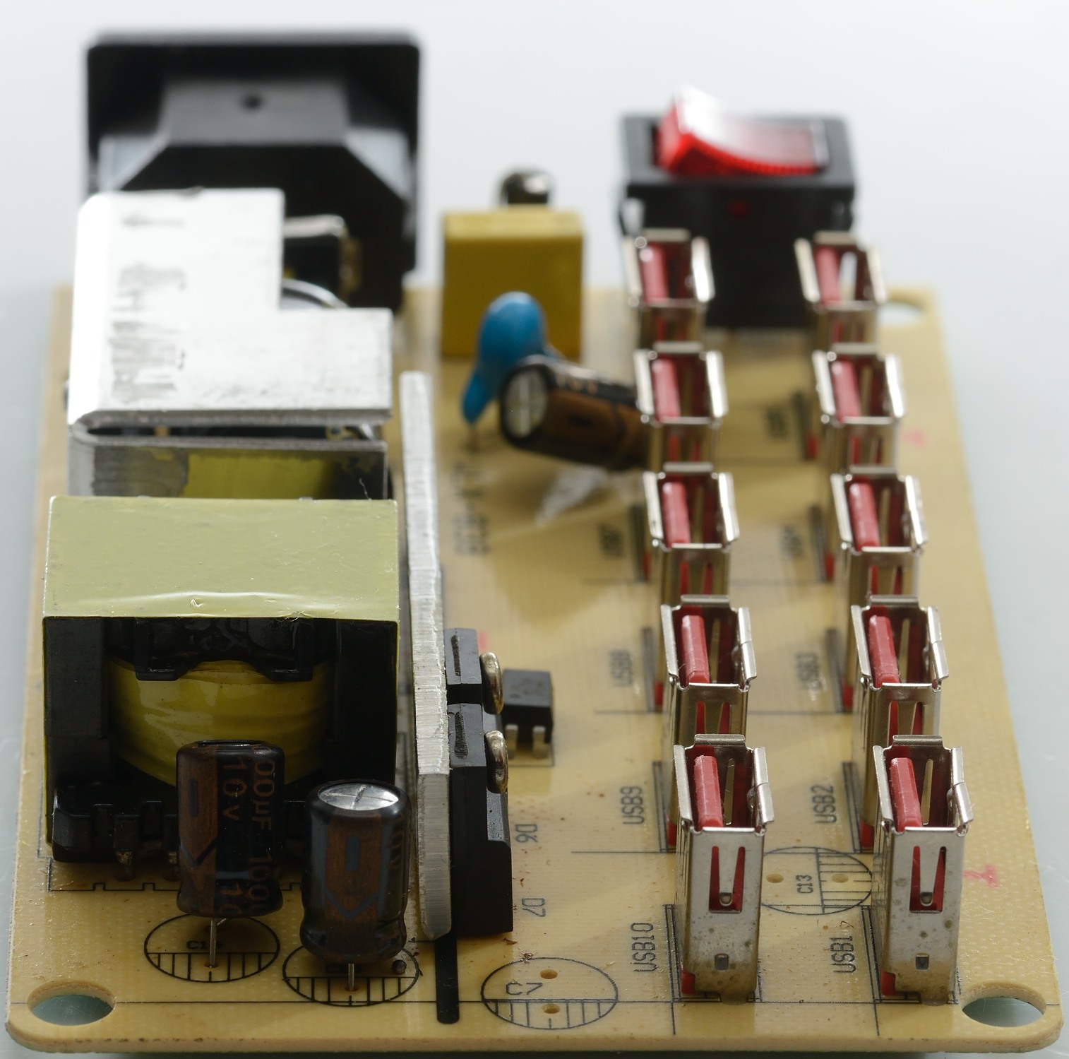
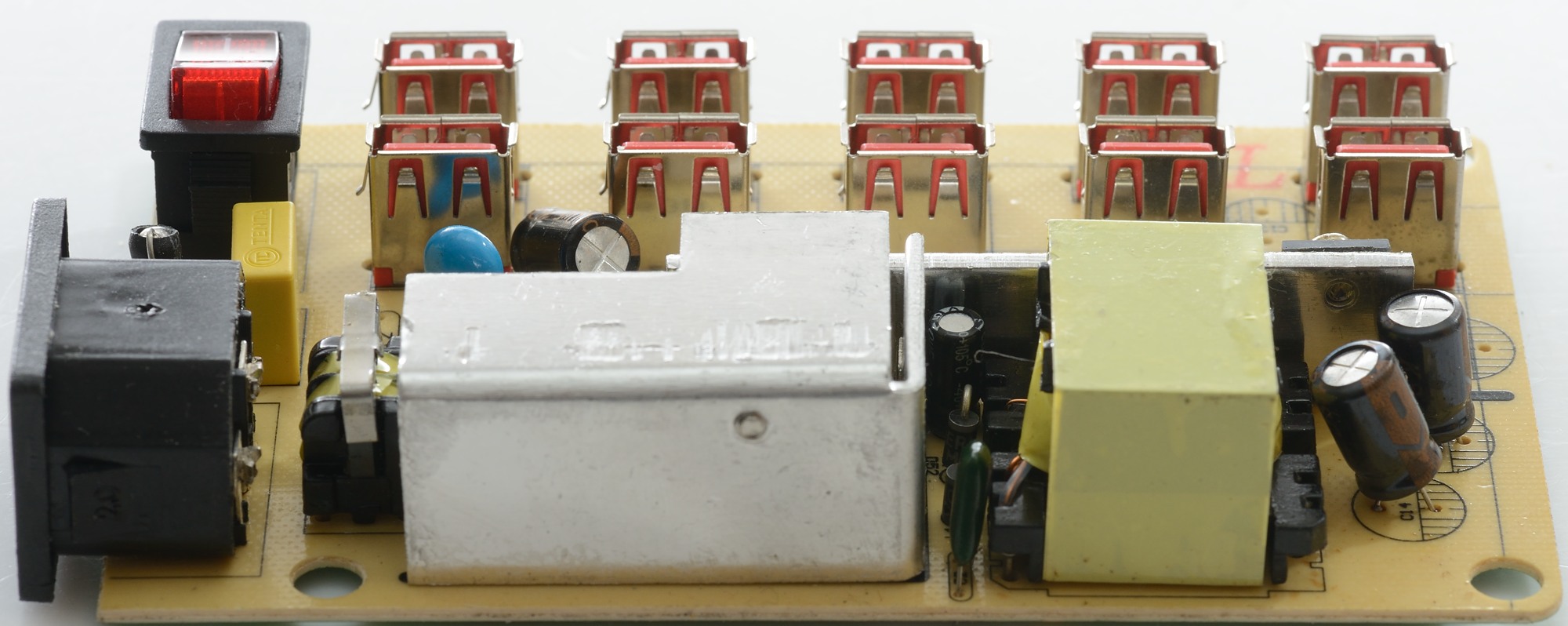
There is enough space to make a fairly clean layout. Between the mains input and the switch is placed a fuse. Behind the mains input us a common mode coil and a bridge rectifier. The heatsink that covers the input capacitor is used for the mains switcher transistor. There is mounted a single safety capacitor.
The two rectifier diodes are mounted on the other heatsink, looking at the thermo photos this heatsink is way too small. There is also a optical feedback.
If the two missing capacitors had been mounted the output would have looked better.

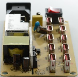

The screw for the switcher transistor can be seen on the heatsink, this transistor must be mounted on the heatsink before the transistor and heatsink is mounted on the circuit board.
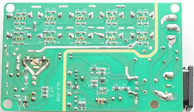
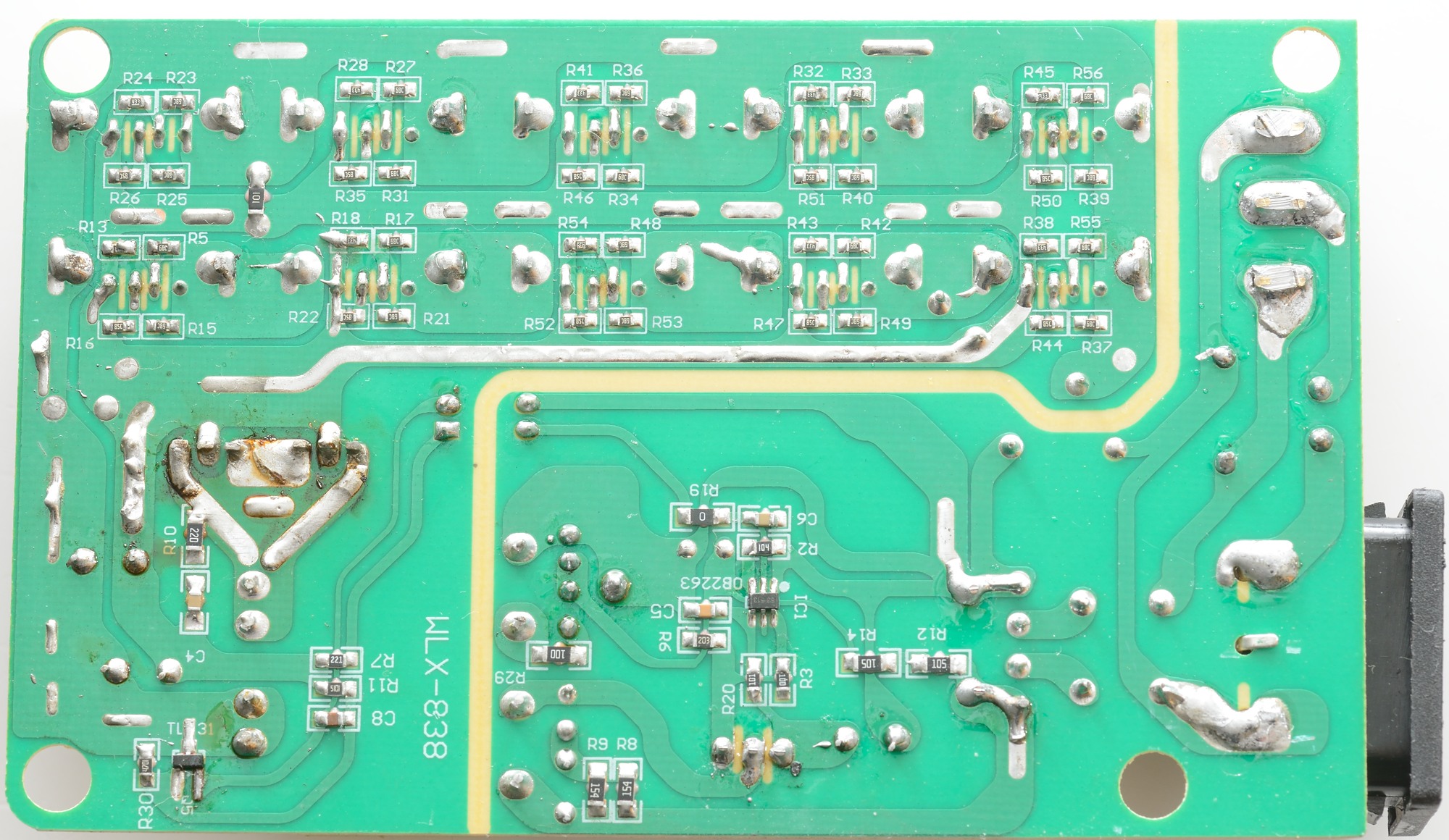
There is not much to see on the bottom side. The mains switcher controller (IC1). Each usb port has its own coding resistors, i.e. it would have been easy to code them individually. It looks like the usb connectors are used as jumpers to transfer power around the board. The earth pin on the mains input is not connected.
Around the two rectifier diodes it looks like the circuit board has been rather hot, I suspect it is from my 1 hour test.
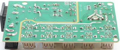
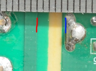
There is a nice isolation barrier on the circuit board, but it not wide enough. It must be over 6mm, but is close to 4mm in some places.
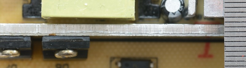
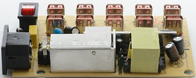
On the topside it also looks bad, the heatsink for the two rectifier diodes are very close to the mains heatsink. Probably for that reason the diodes used are in a isolated package, but because the heatsink goes down to the circuit board there is very little distance from the pins on the diodes (That are low voltage side) to the heatsink (That can be connected to mains if you drop the charger).
The charger passed an isolation test with 2500 volt, but failed a 5000 volt test.
Conclusion
I like the idea with a small charger with many outputs and ability to charge any usb device, but this charger do not fulfil this, it gets too hot, cannot handle all devices with optimal current and is also unsafe.
Notes
Index of all tested USB power supplies/chargers
Read more about how I test USB power supplies/charger