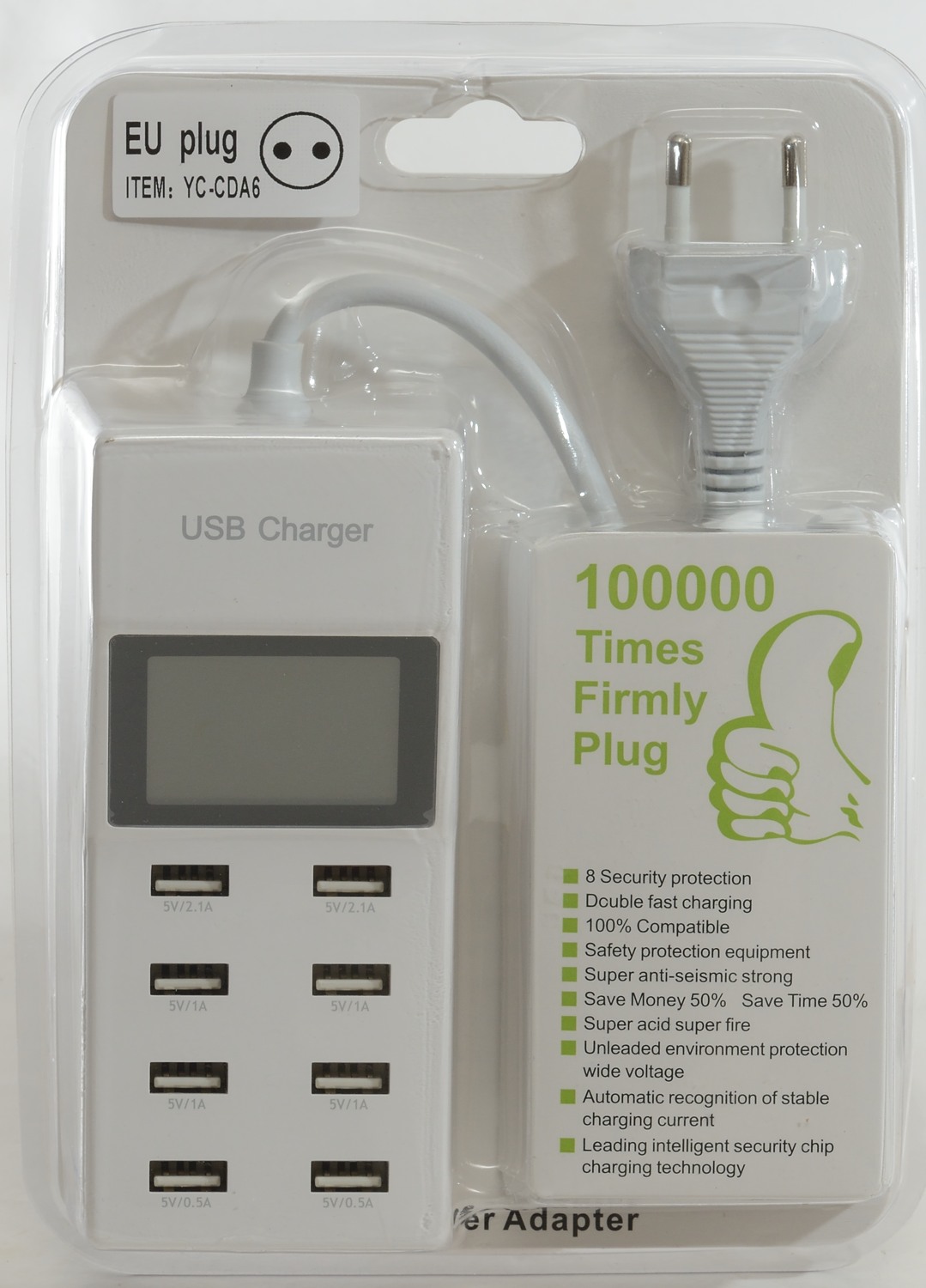
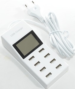
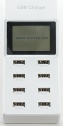
8 port usb charger YC-CDA6
Official specifications:
- 8 USB ports with various output capacity to meet your needs
- Compatible with all smartphone and tablet PC Camera MP3 MP4 Player with USB port
- Charge up to 8 devices at the same time.
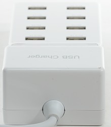
- 1.5M wire
- Comes with display screen to show charging status clearly,comes with a smart LED screen to check the status
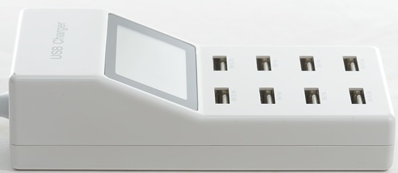
- Compact design,small size and light weight
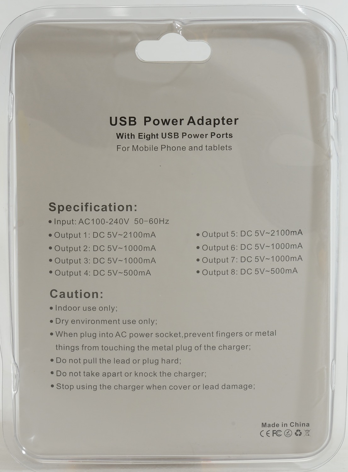
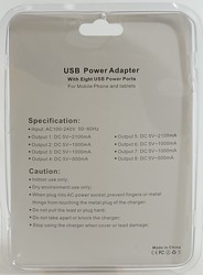
- USB output: DC 5.0V ~ 2.1A (for port 1 & 5) DC 5.0V ~ 1A (for port 2 3 6 7) DC 5.0V~0.5A (for port 4 & 8)
- Input Voltage: AC 100-240V 50-60 HZ
- Socket size: 13.5 x 6 x 2 cm (L x W x H)
- Color: White
- Plug standard: UK plug,US plug,EU Plug(optional)
I got it at aliexpress: SZ HUIBANG TRADING

I got it in a retail package without any accesories.
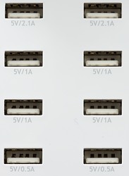
The current marking on the ports are not related to the output capability, but some of them match the coding.
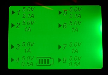
The display shows voltage, current rating and a animated icon for all ports with loads on. The display may look technical, but it is not, except the animated icons, everything else is just fixed text.
Measurements
- Power consumption when idle is 0.15 watt.
- 2.1A ports are coded as Apple 2.1A
- 1A ports are coded as USB charger (DCP)
- 0.5A ports are coded as Apple 2.1A (Oops)
- All outputs are in parallel.
- Display will turn on if any port is loaded with more than 53mA


All ports looks the same and there is no individual over current protection.
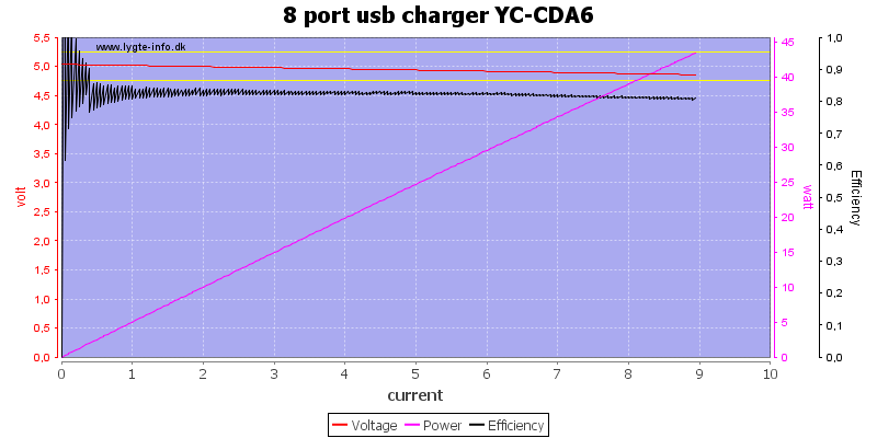
Running all port in parallel I can draw nearly 9A, this is very close to the rated 9.2A.
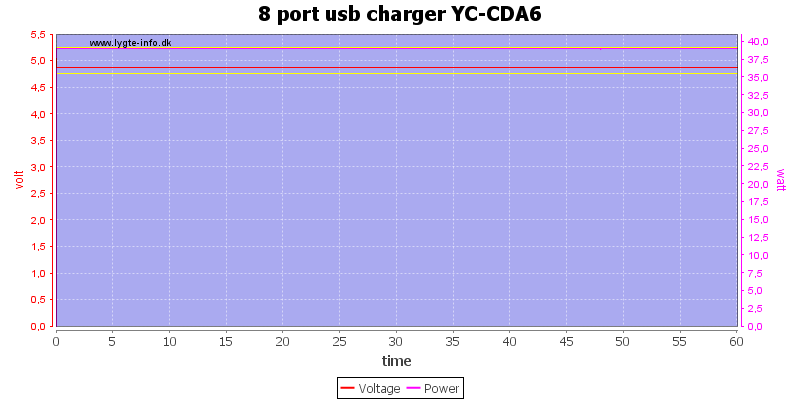
I decided to run the one hour load test at 8A and it could handle that.
The temperature photos below are taken between 30 minutes and 60 minutes into the one hour test.
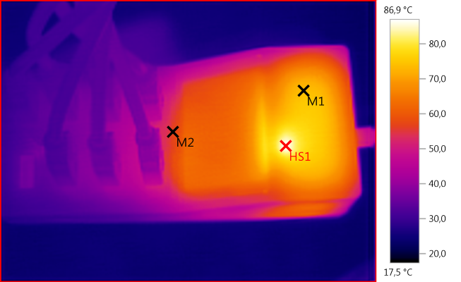
M1: 73,7°C, M2: 56,6°C, HS1: 86,9°C
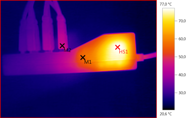
M1: 56,0°C, M2: 45,5°C, HS1: 77,0°C
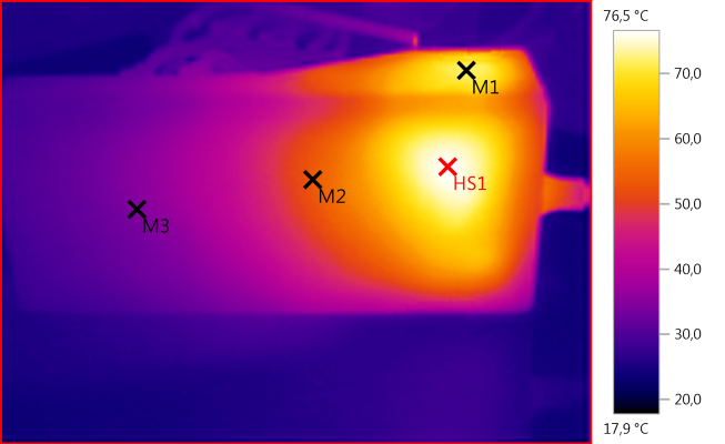
M1: 71,8°C, M2: 53,5°C, M3: 34,4°C, HS1: 76,5°C
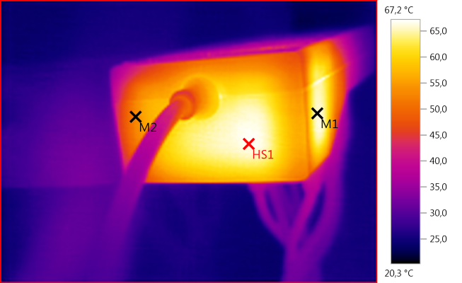
M1: 65,8°C, M2: 53,0°C, HS1: 67,2°C
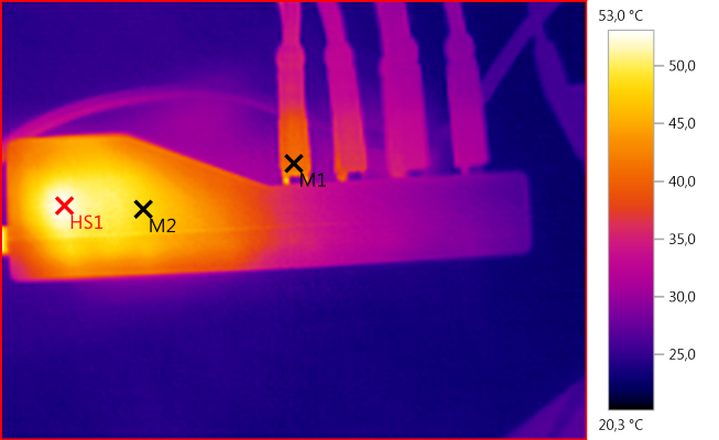
M1: 41,2°C, M2: 48,4°C, HS1: 53,0°C
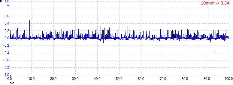
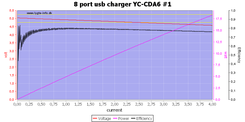
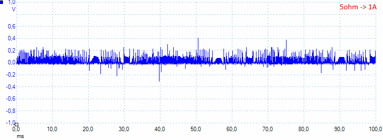
The charger has a lot of peak noise at low load: 37mV rms and 1000mVpp
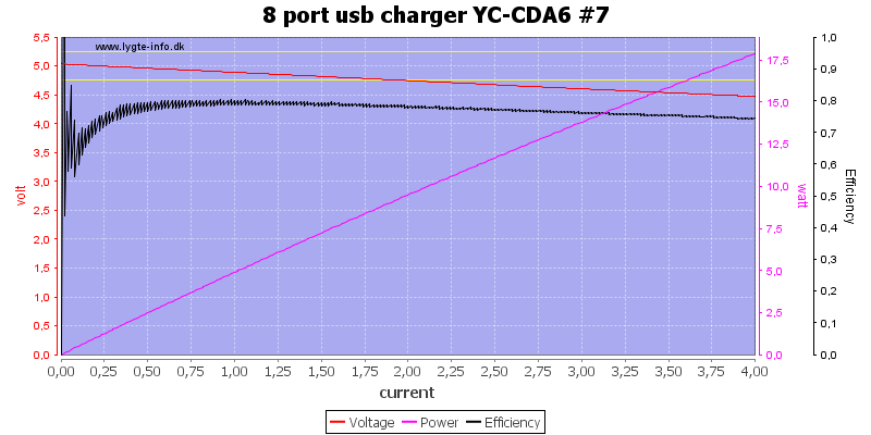
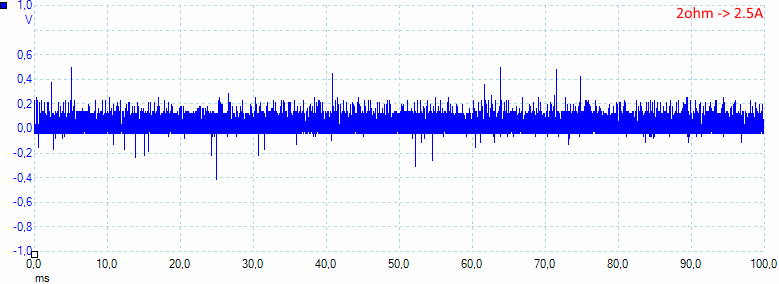
The rms noise increase with load: 44mV rms and 953Vpp
More noise: 68mV rms and 1200mVpp
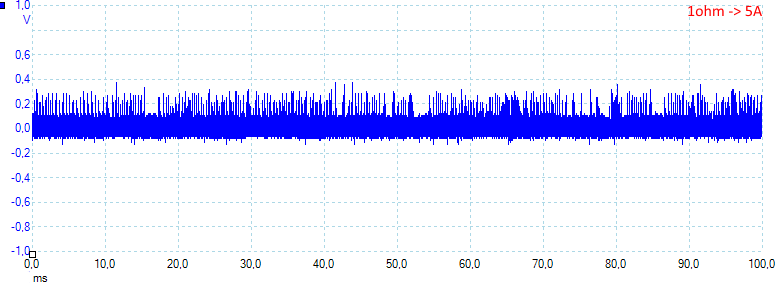
At 5A the peak noise is not that bad anymore: 88mV rms and 580mVpp
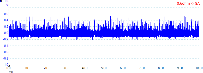
At 10A it increases again: 107mV rms and 800mVpp
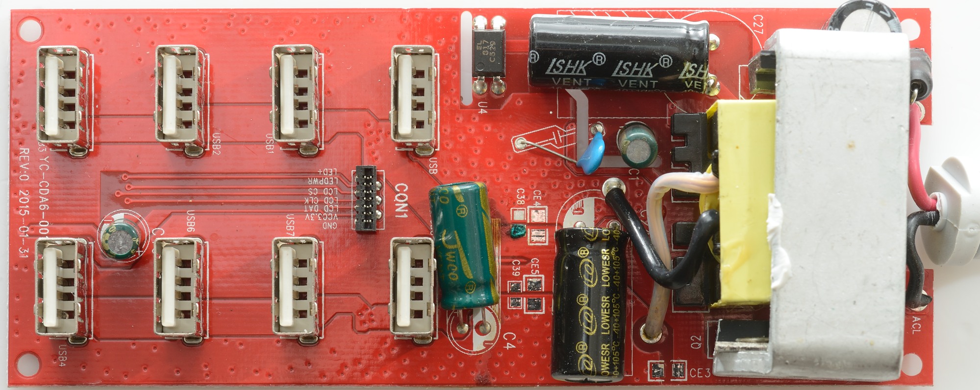
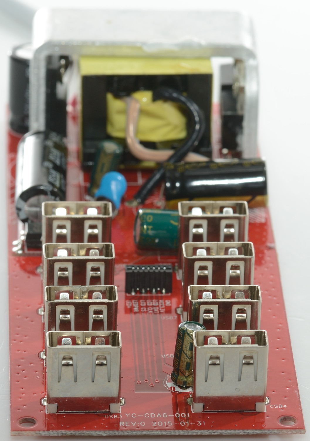
Tear down
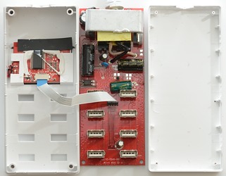
This was closed with a couple of plastic snaplocks, no glue or screws.
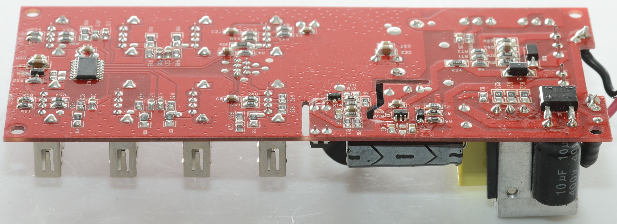
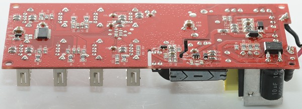
At the input is a fuse. Above the transformer is a heatsink, it has the mains switcher mounted on one side and two rectifier diodes on the other side. There is a safety capacitor and a opto feedback chip (U4).
The connector for the LCD display is marked with the signals and it can be seen that it is a serial databus and some power connections.
There is no EMC parts (Like a common mode coil), this means it will not pass a EMC test.
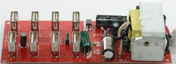
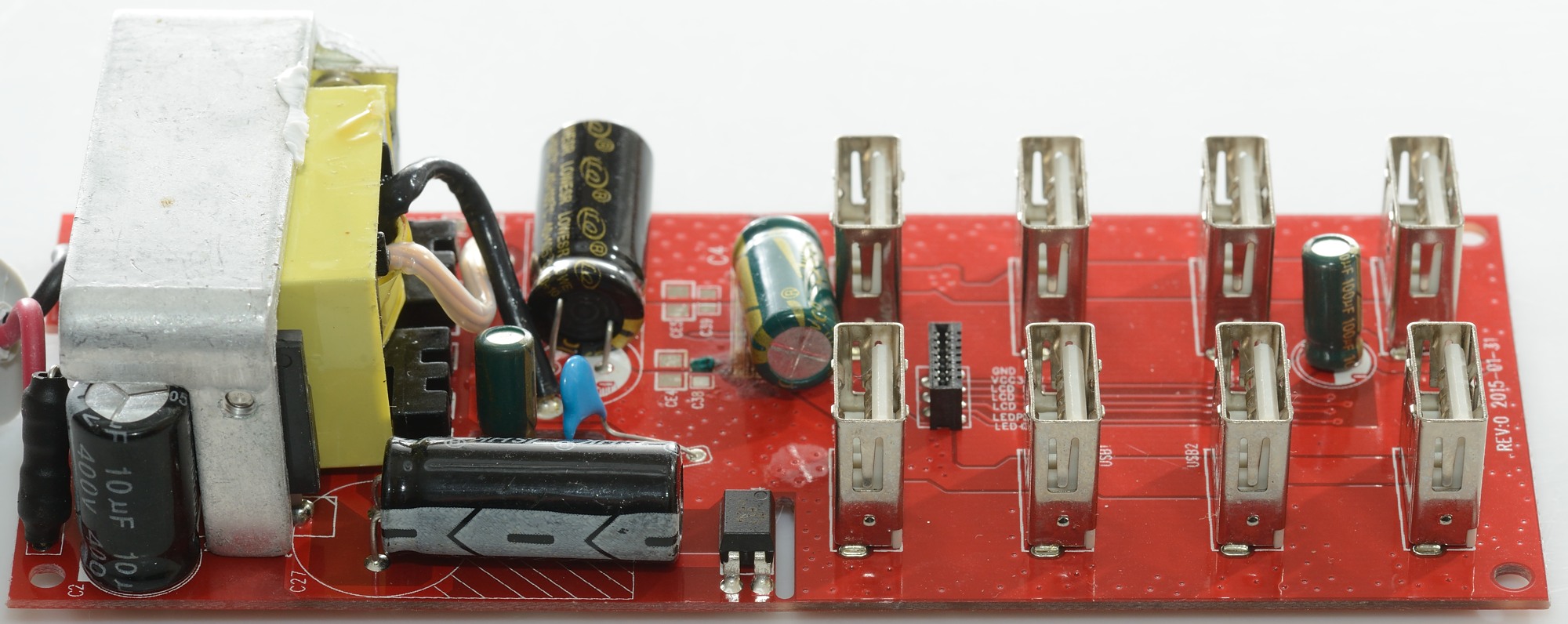
A small part of the one rectifier diodes can be seen on the heatsink, screws for both the rectifier diodes can be seen.

The fuse and the opto coupler is mounted close to this side. The switcher transistor can be seen on the heatsink.

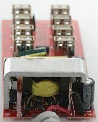
The fuse can easily be seen here.

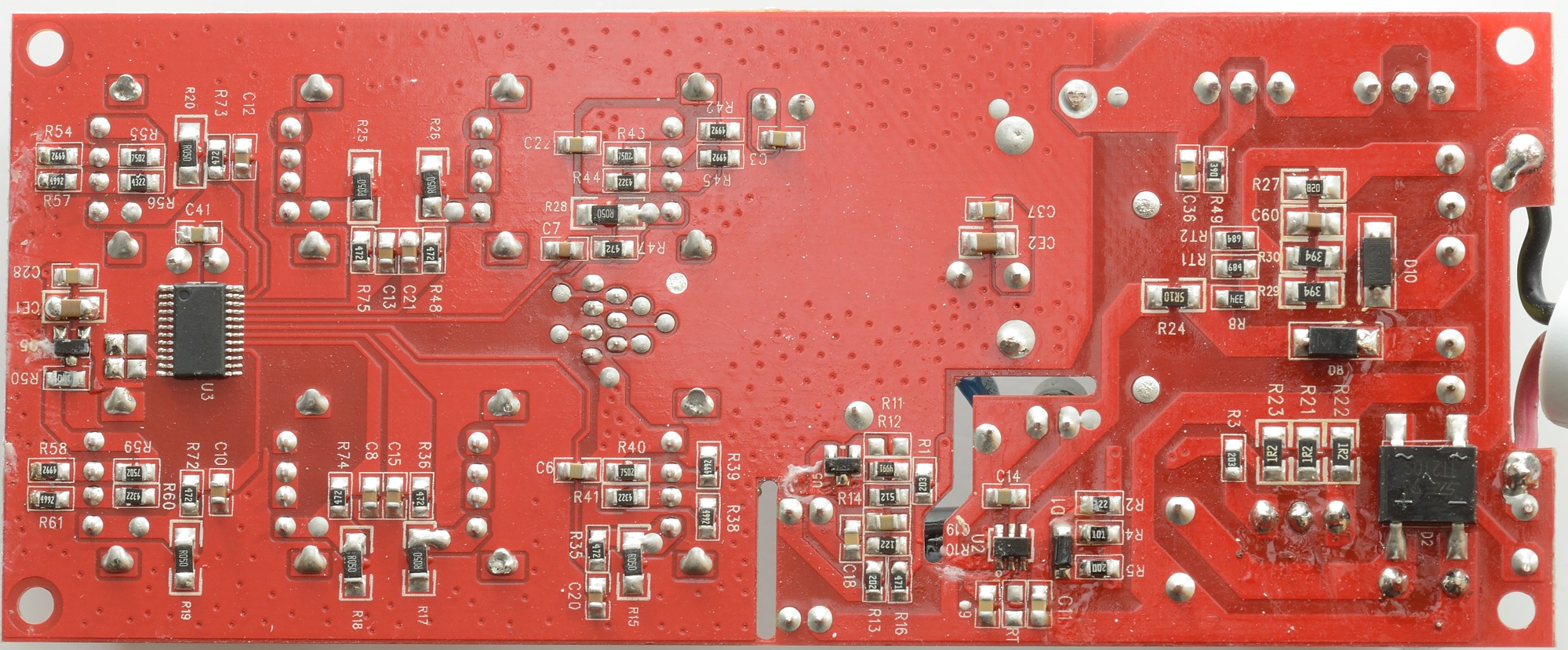
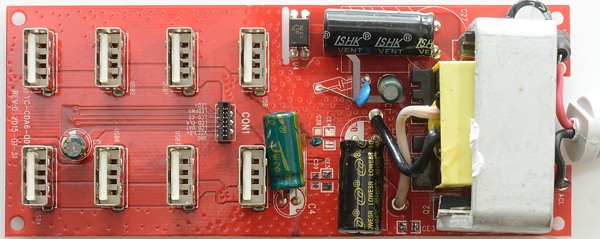
On this side of the circuit board is the bridge rectifier (D2), the switcher controller (U2) and the chip that check if any usb output is using power (U3). There is no marking on it, but it must be a microcontroller with analog to digital converters. All outputs has a R050 resistor for checking on current consupmtion.
Four usb output has resistors for coding and four has the data pins shorted.
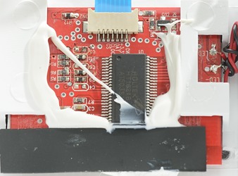
There is a Holtek chip to control the display (HT1621B), it can control 128 elements on the display.
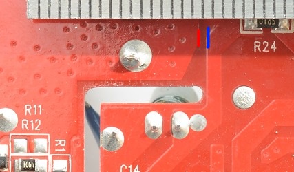
There is virtually no isolation distance, but because the circuit board is coated it can handle the 5000 volt.
Testing with 2500 volt and 5000 volt between mains and low volt side, did not show any safety problems.
Conclusion
This charger has a fancy display, but it is not very useful. The noise is on the high side and individual port protection is missing, there is also a total lack of any EMC handling. I do not like the safety on the charger.
Notes
Index of all tested USB power supplies/chargers
Read more about how I test USB power supplies/charger