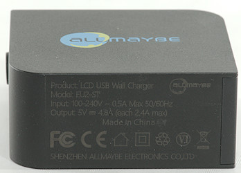
Allmaybe LCD USB Wall charger EU2-ST
Official specifications:
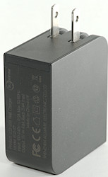
- Power: 24W
- Input: 100-240V 50/60Hz
- Operating temperature: 0°C ~ 45°C
- DC Output: 5V 4.8A (Each 2.4A max)
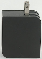
- Size: 65.5 * 55 * 28.3mm
- Weight: 95g
I got it directly from Allmaybe


I got it in a white cardboard box.
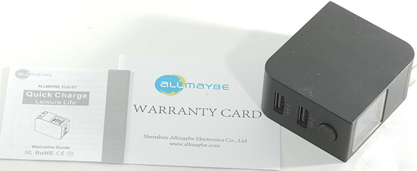
The box contained the charger, a warranty card and a instruction sheet.
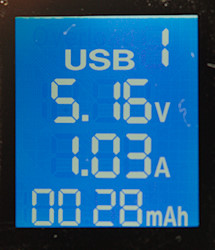
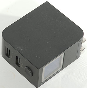
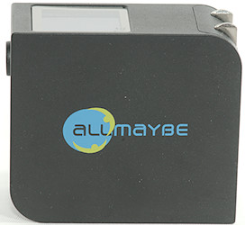
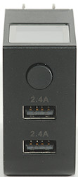
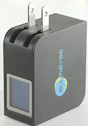
This charger has a display that shows volt, current and charged capacity.
The button is used to select between usb 1 and usb 2 and to reset the mAh counter, removing power will also reset the mAh counter.
Measurements
- Power consumption when idle is 0.18 watt
- All usb output is coded as auto coding with Apple 2.4A as maximum.
- Positive usb outputs are in parallel, negative has the protection.
- Weight is 85.2 grams.
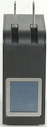
- Size is 63.5 x 56 x 28.3mm with folded plug
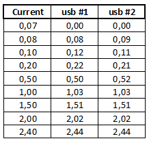
The display will first show current when it is above about 80mA and as can be seen from the table precision is about 0.04mA.
Voltage is correct when unloaded, when loaded there will always be some voltage drop in the connector and cable the readout cannot include.
Usb #1 can deliver 2.7A before overload protection trips.
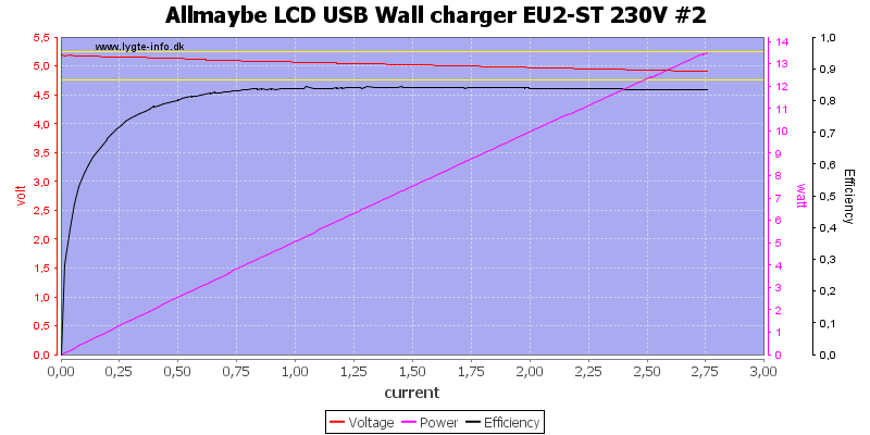
Same with usb #2.
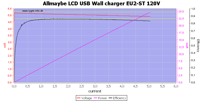
But together I could draw 5A, i.e. there are individual port protection, HERE AT 120vac.

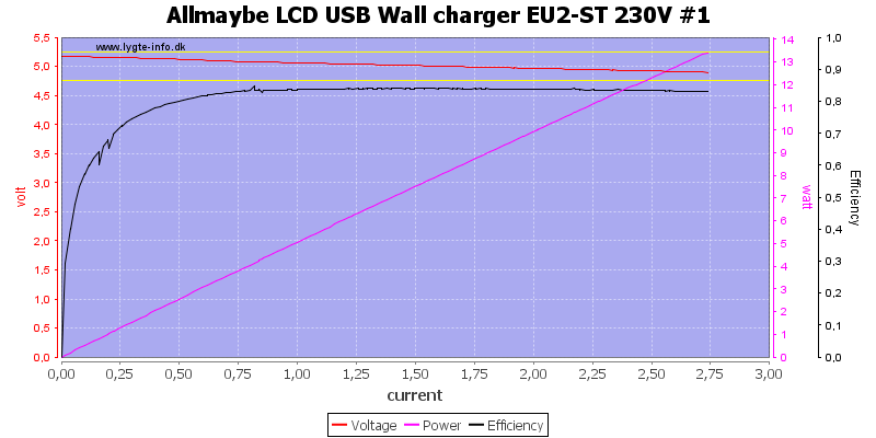
And here at 230VAC
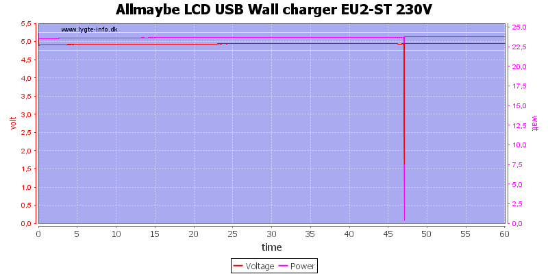
And the charger can deliver 4.8A for one hour. The tick at 47 minutes is because I am handling it to get the IR photos below.
The temperature photos below are taken between 30 minutes and 60 minutes into the one hour test.
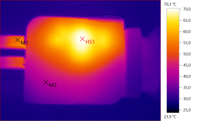
M1: 53,4°C, M2: 40,9°C, HS1: 70,3°C
HS1 is the transformer.
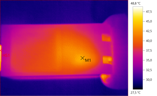
M1: 43,0°C, HS1: 48,8°C
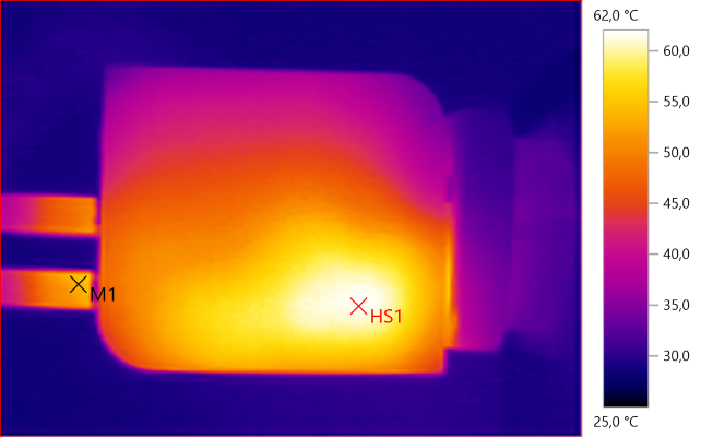
M1: 53,9°C, HS1: 62,0°C
Again HS1 is the transformer.
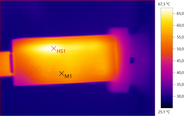
M1: 56,2°C, HS1: 67,3°C
Here HS1 is probably due to the rectifier.

HS1: 69,6°C
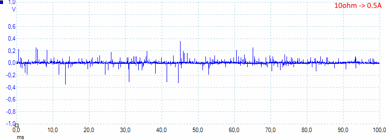
At 0.5A the noise is 24mV rms and 800mVpp.
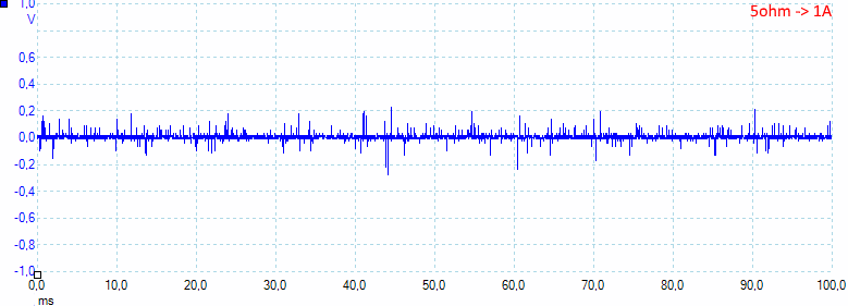
At 1A the noise is 18mV rms and 552mVpp.
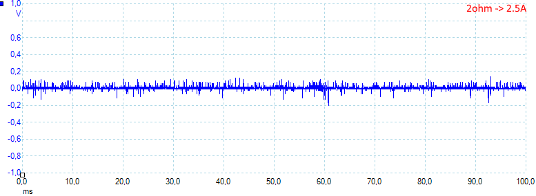
At 2.5A the noise is 25mV rms and 578mVpp
At 5A the noise is 28mV rms and 576mVpp
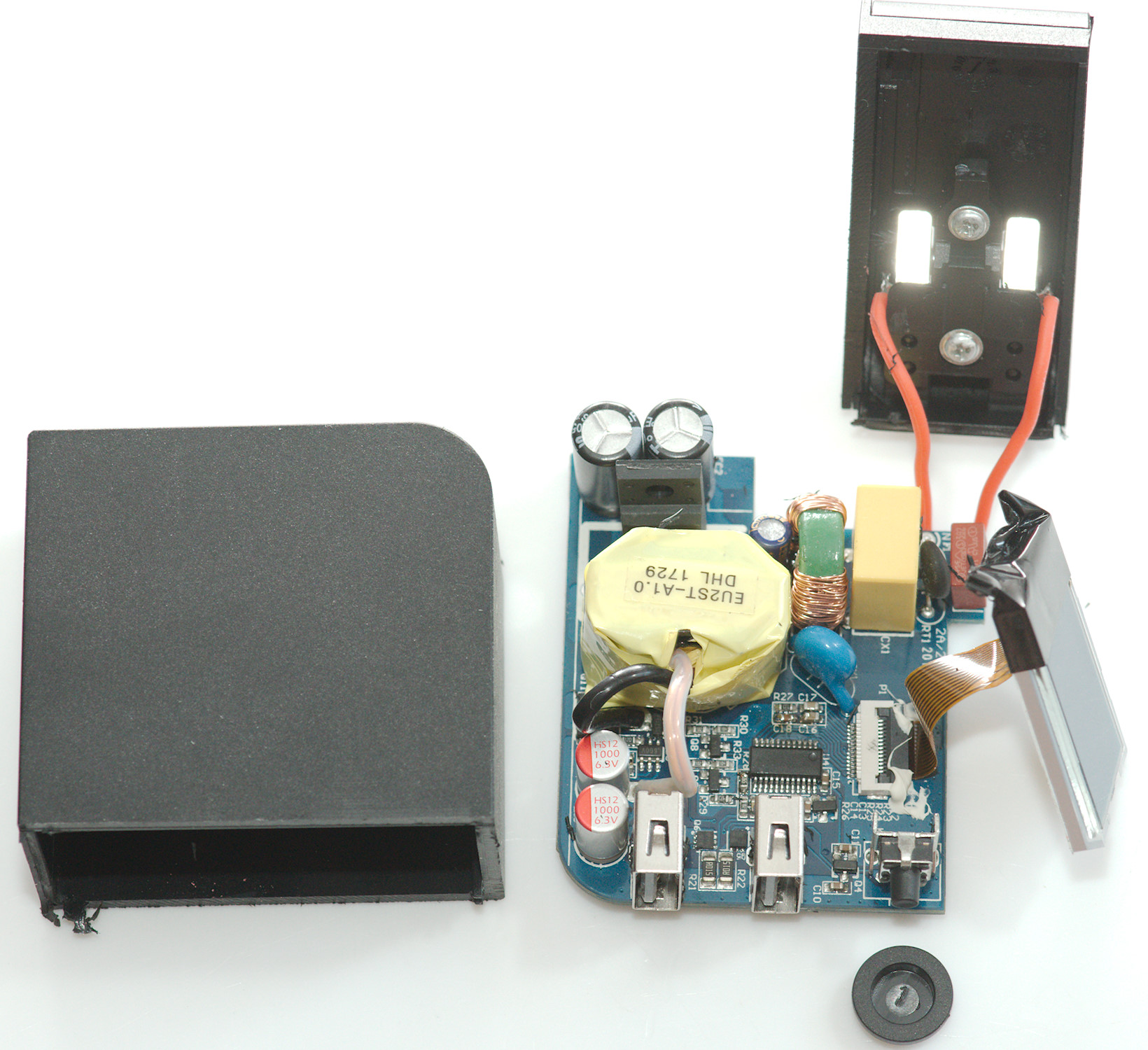
Tear down
I could not see a good place to squeeze or hit this charger (I would prefer to keep display intact), I went directly to cutting.
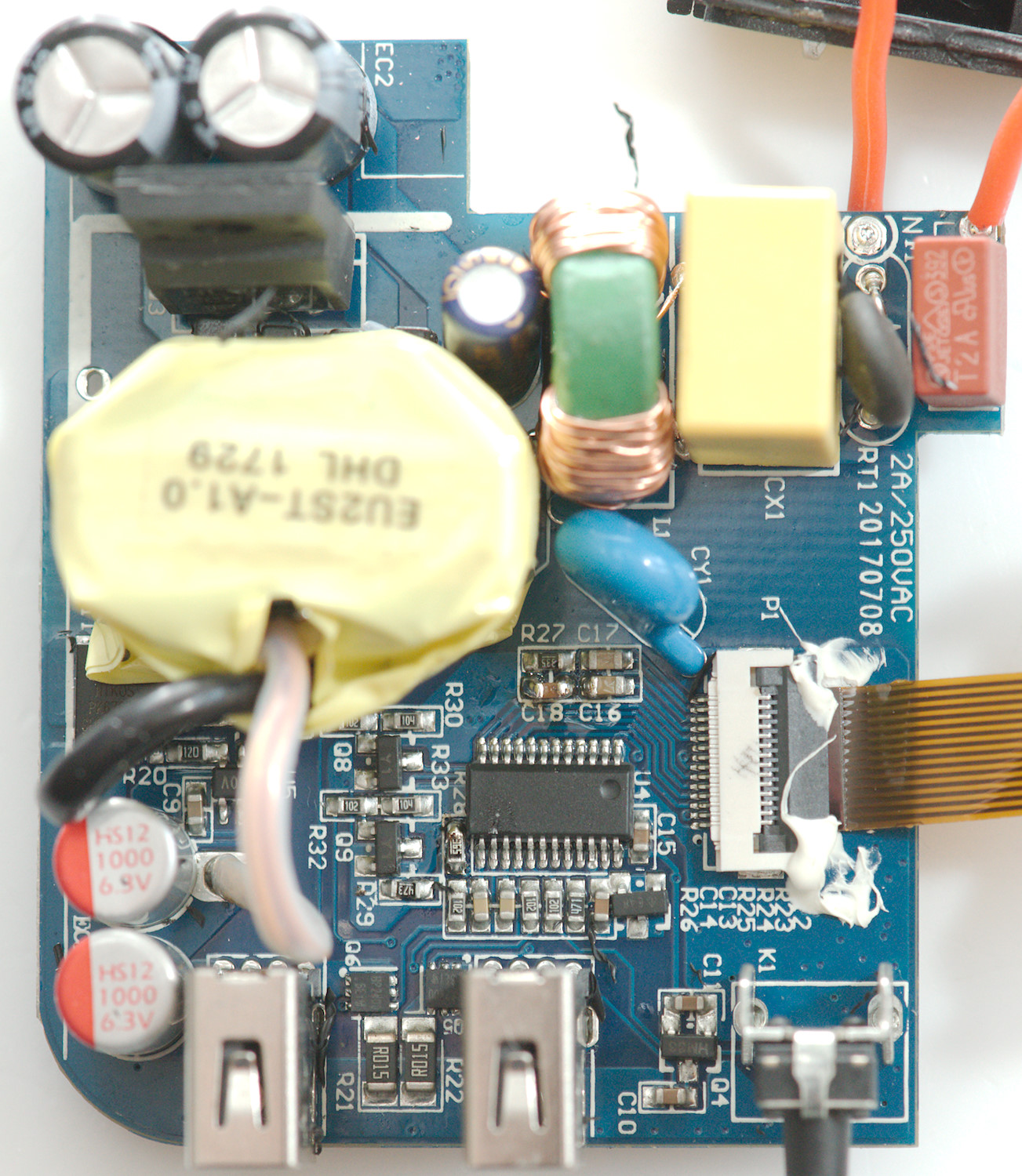
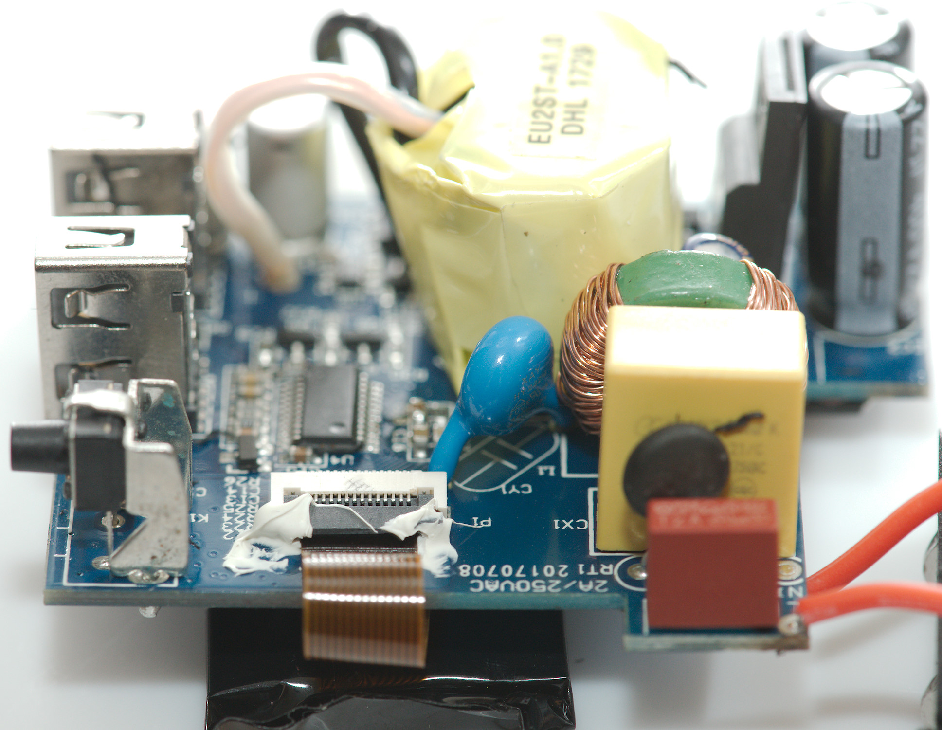
At the mains input is a fuse (F1) and a inrush current limiter (RT1) followed by a X capacitor and a common mode coil (L1) with the safety capacitor (CY1) next to it. There is also a mains switcher transistor (Q3).
On the low volt side is a synchronous rectifier (U5 & Q11). The microcontroller (U4) with a connector to the display.
Between the two usb connectors is two power mos transistors (Q5 & Q6) to turn output on/off and some 0.015ohm resistors (R21 & R22) to measure the current across.
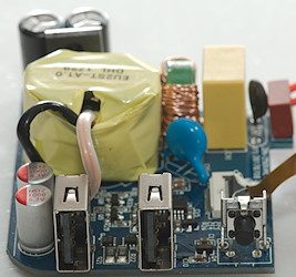
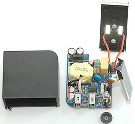
On the first photo the usb connectors with the current sense resistors between are in front, together with the switch.
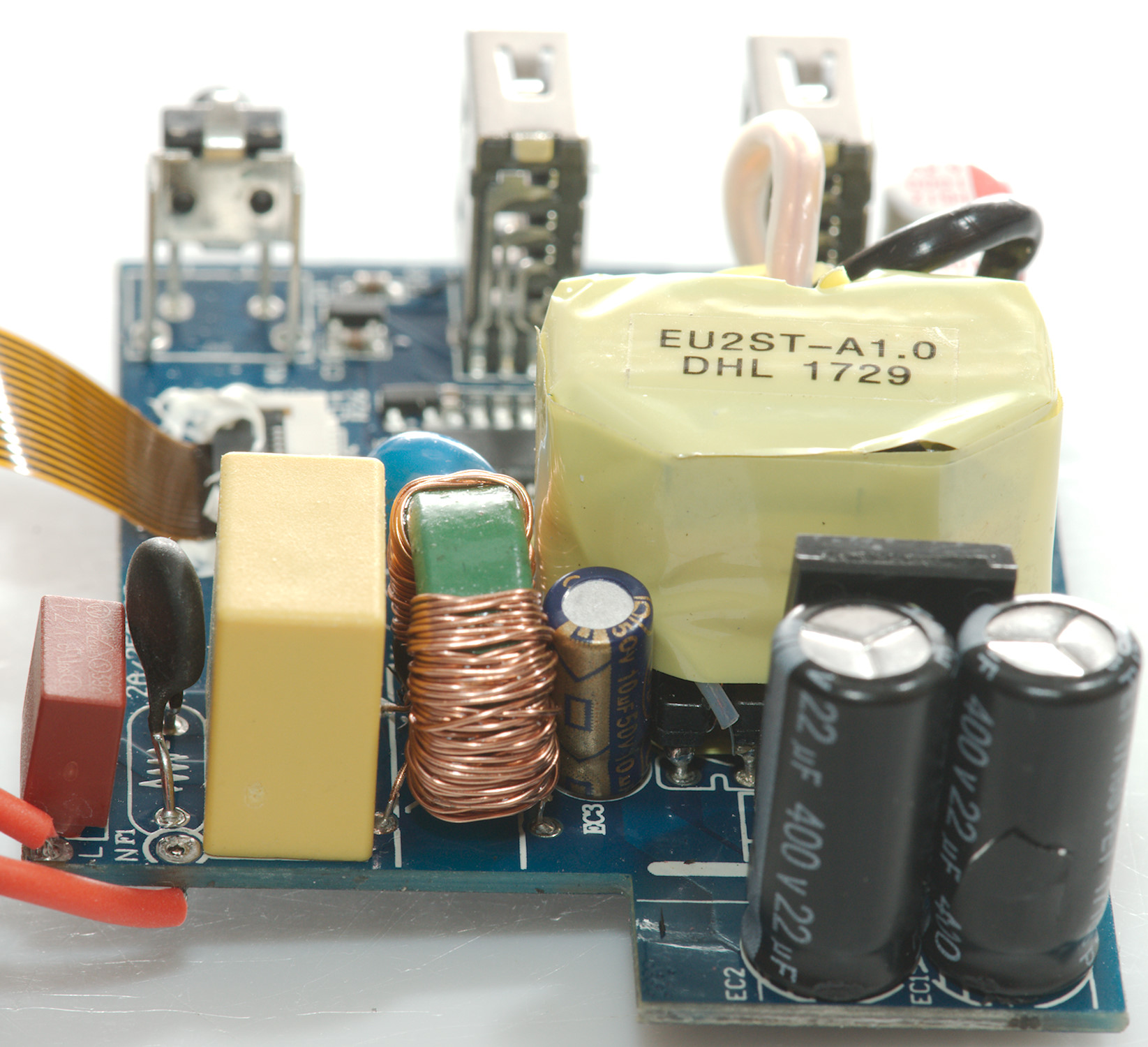
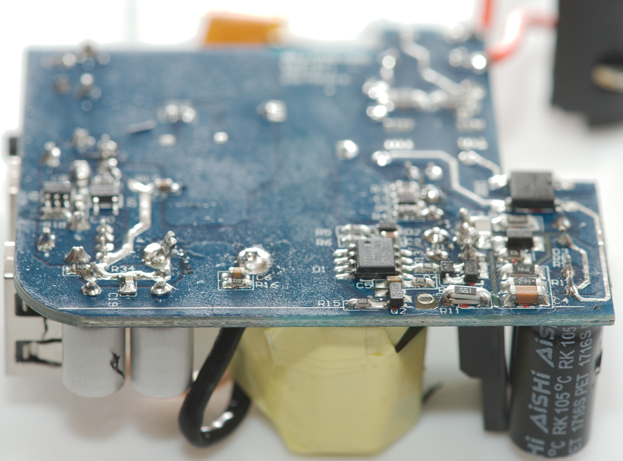
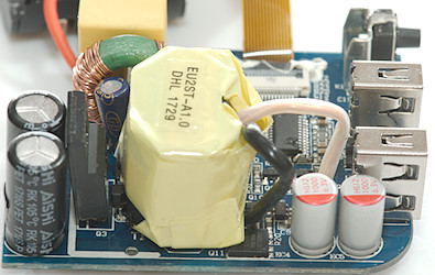
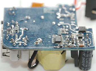
On the second photo the rectifier transistor (Q11) can be seen under the transformer and mains switcher (Q3).
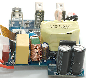
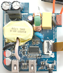
On the first picture the common mode coil is in front.
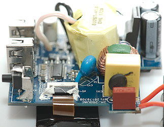
The second picture shows the connector for the display with the plug glued in (In a sealed box that is a good idea).
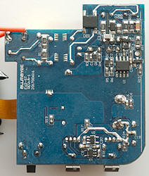
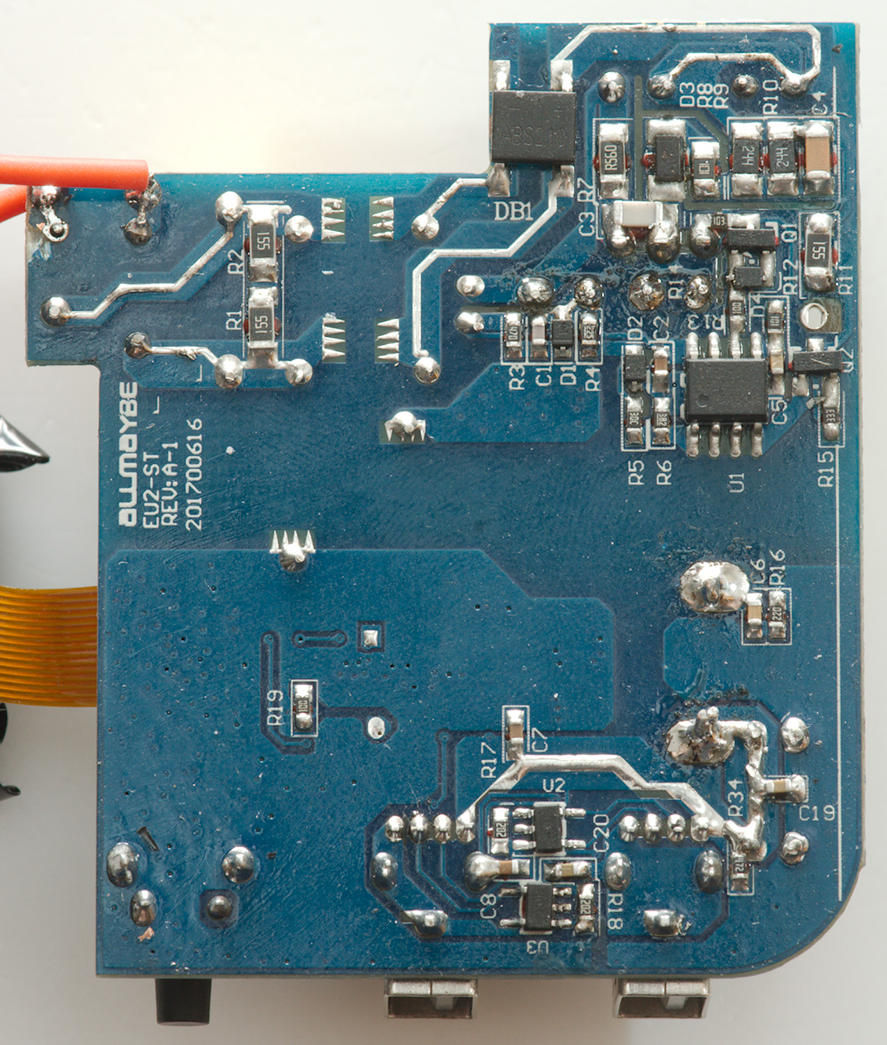
On this side of the circuit board is the bridge rectifier (DB1) and the mains switcher controller (U1).
Below the usb connectors are the auto coding chips (U2 & U3).
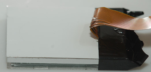
The display includes a backlight, the flat flex cable is also secured here.
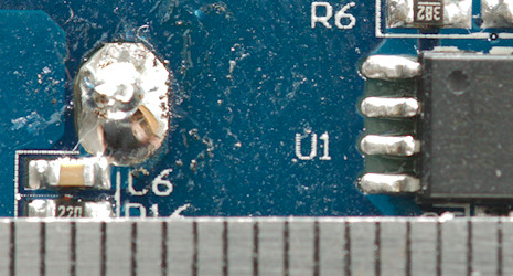
Safety distance looks fine.
Testing with 2830 volt and 4242 volt between mains and low volt side, did not show any safety problems.
Conclusion
This is a powerful two port charger with auto coding and display of current and capacity for each port. The charger also looks safe.
Notes
The usb charger was supplied by Allmaybe for a review.
Read more about how I test USB power supplies/charger