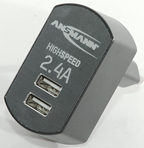
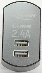
Ansmann 2.4A High Speed USB charger ANB0114
Official specifications:
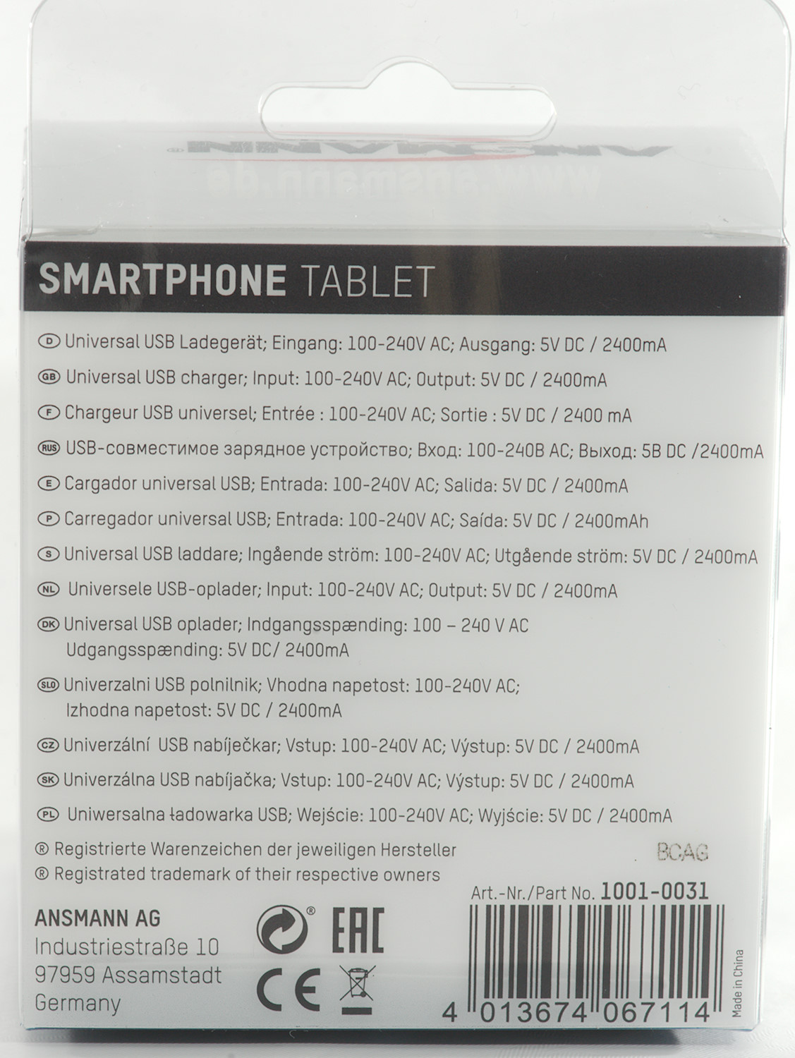
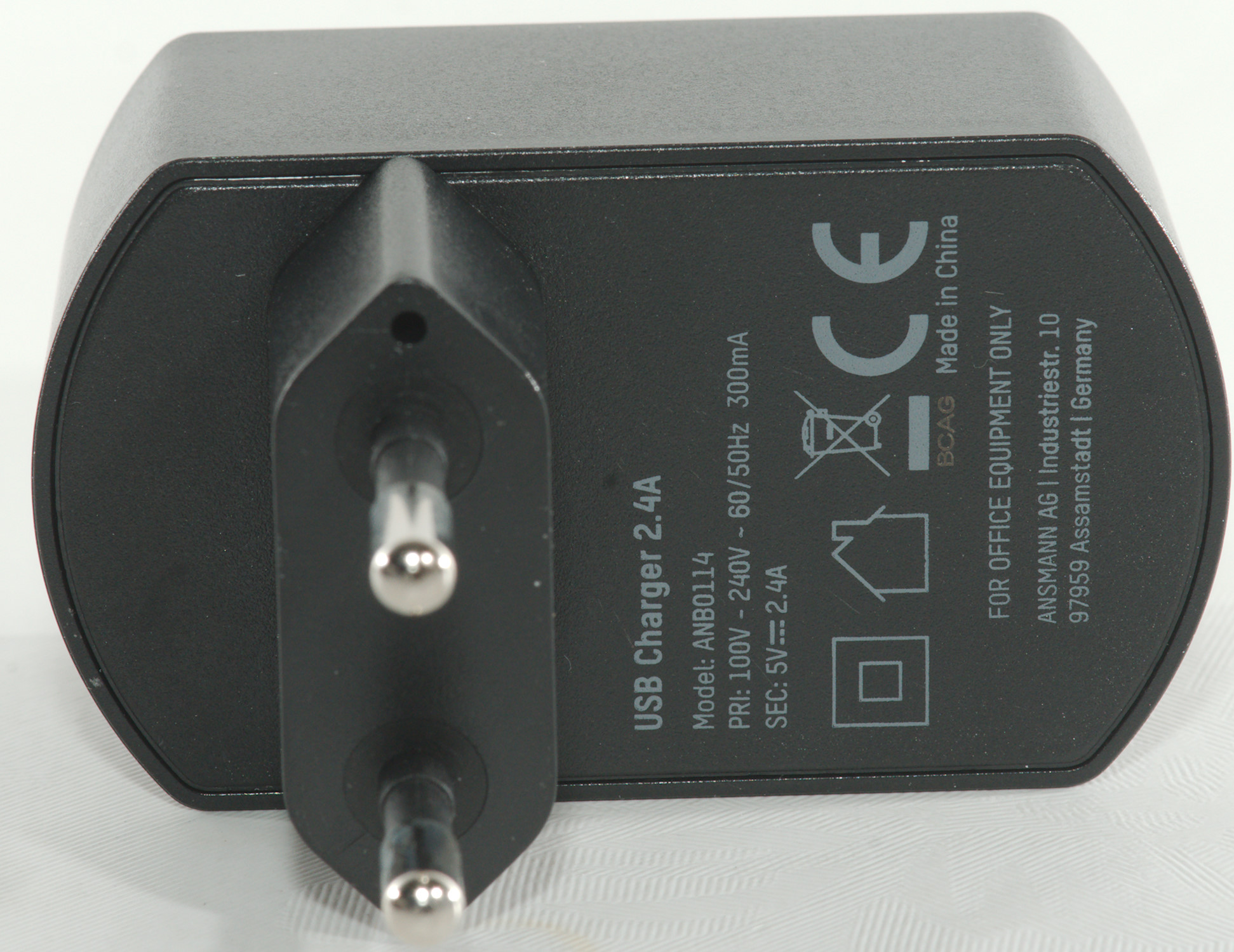
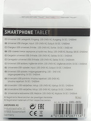
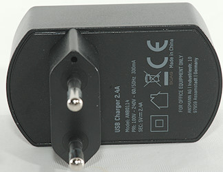
- Input: 100-240V 50/60Hz
- DC Output: 5V 2.4A
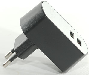
- Size: 60 × 34 × 61 mm
- Weight: 58g
I got it from Ansmann
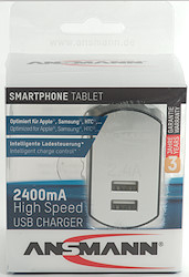
I got it in a plastic box.
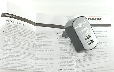
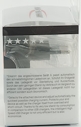
The box contained the charger and some safety instructions.
Measurements
- Power consumption when idle is 0.01 watt
- Usb outputs is coded as auto with Apple 2.4A as max.
- Usb outputs are in parallel.
- Weight is 57.1 grams.
- Size is 62.3 x 62.2 x 35.3mm
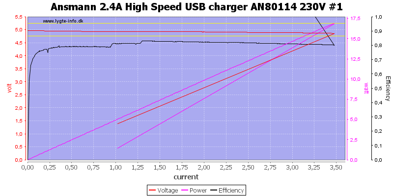
The first output can deliver 3.5A before overload protection kicks in.
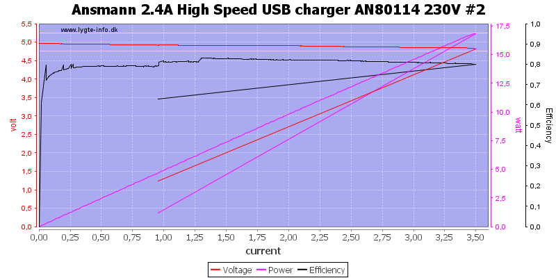
And the second output is the same.
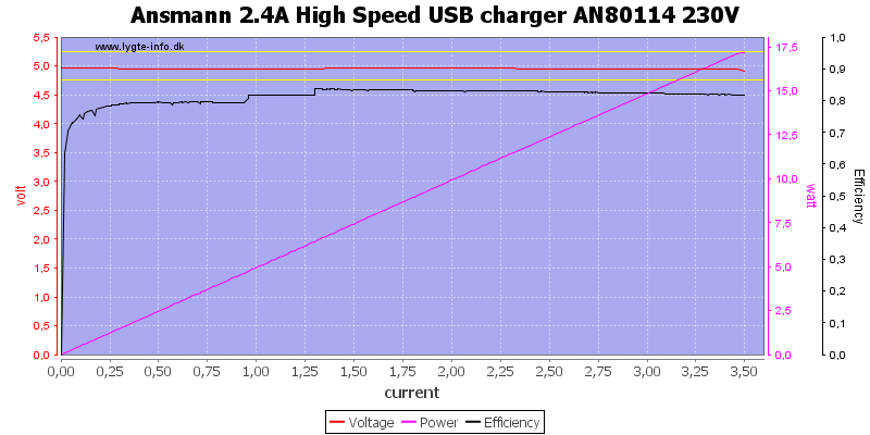
And both at the same time is exactly the same, they are in parallel.
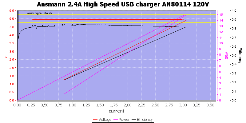
At 120VAC the maximum current is reduced a bit, but still well above the rated 2.4A
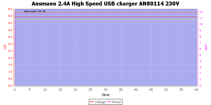
And the charger can deliver 2.4A for one hour.
The temperature photos below are taken between 30 minutes and 60 minutes into the one hour test.
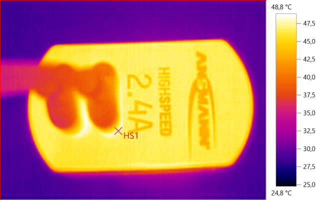
HS1: 48,8°C
The aluminium frontplate secures a mostly uniform temperature on the front.
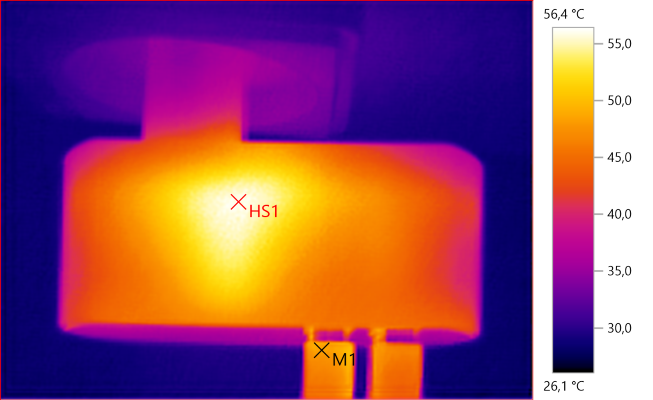
M1: 48,2°C, HS1: 56,4°C
HS1 is the transformer.
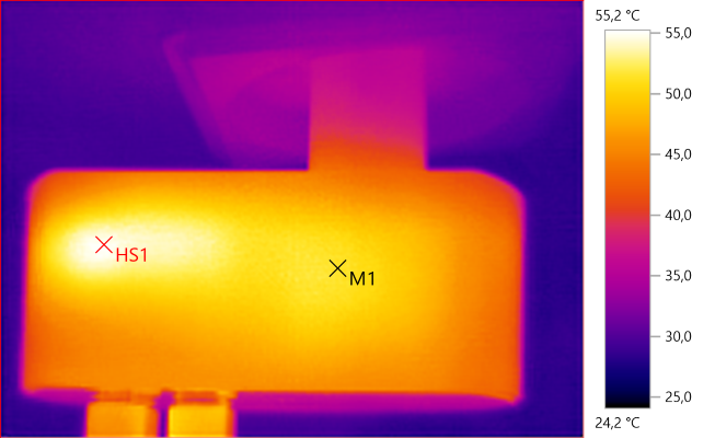
M1: 51,6°C, HS1: 55,2°C
HS1 is the rectifier transistor.
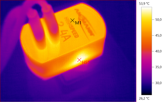
M1: 47,9°C, HS1: 53,9°C
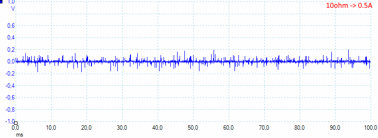
At 0.5A the noise is 19mV rms and 454mVpp.
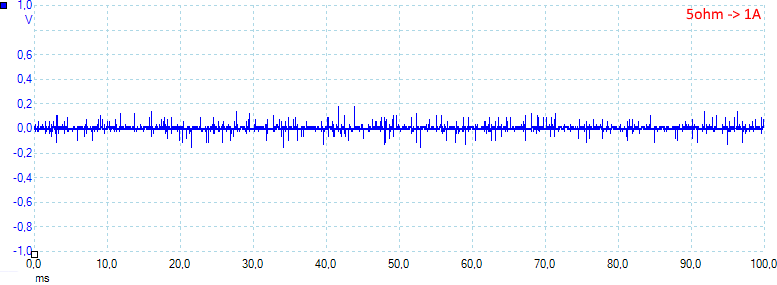
At 1A the noise is 18mV rms and 402mVpp.
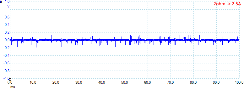
At 2.5A the noise is 25mV rms and 415mVpp.
Tear down
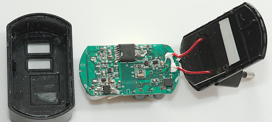
A squeeze with my vice and I could break it open.
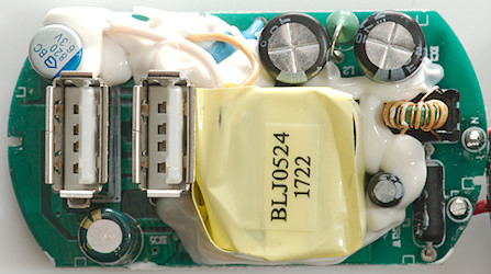
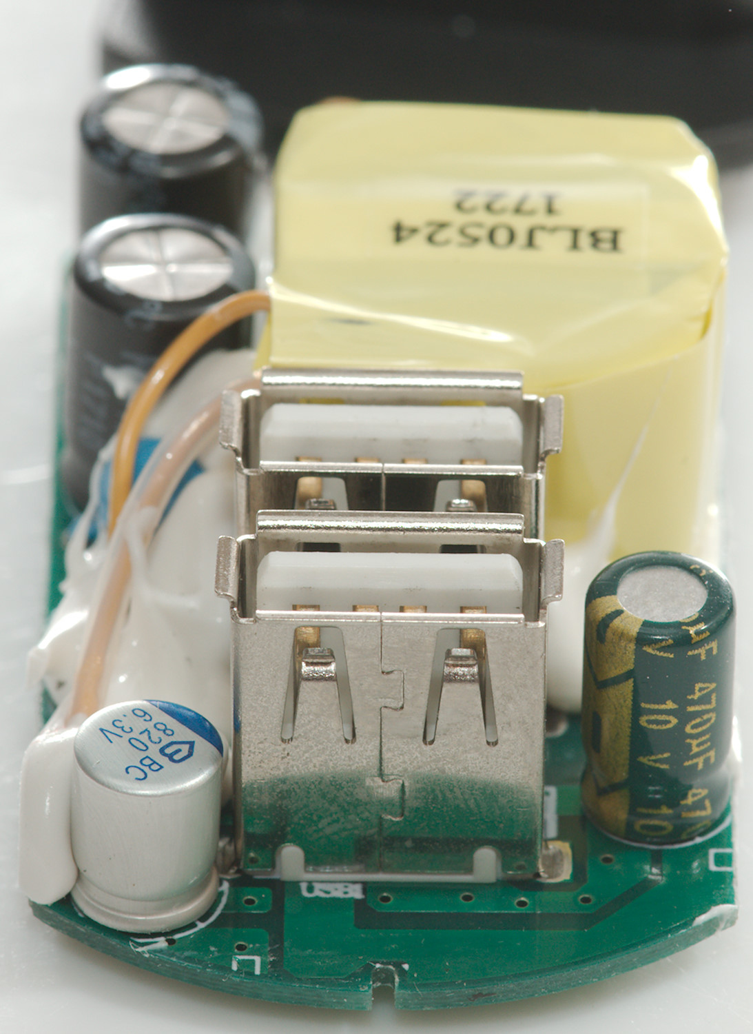
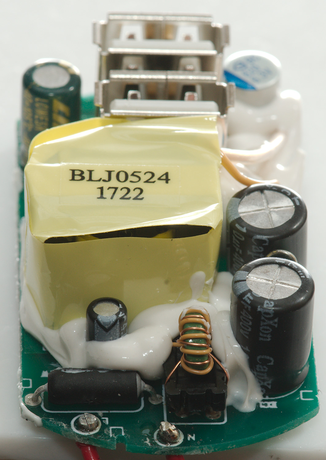
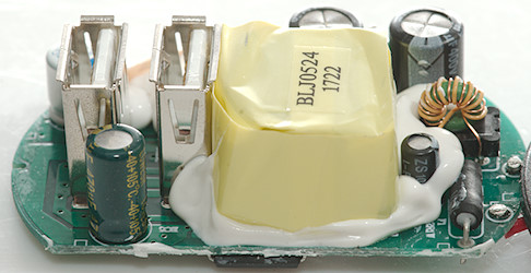
At the mains input is a fuse (F1) followed by a common mode coil. There is an inductor between the two large mains smoothing capacitors.
The inductor between the two smoothing capacitors and the safety capacitors can be seen here. The transformer uses flying wires for the low voltage output to increase safety distance. There is also a lot of yellow tape around it, because it is placed very close to the usb connector.
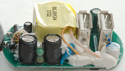
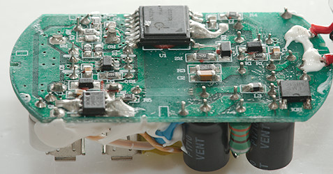
On the second picture the fuse and common mode coil is in front.
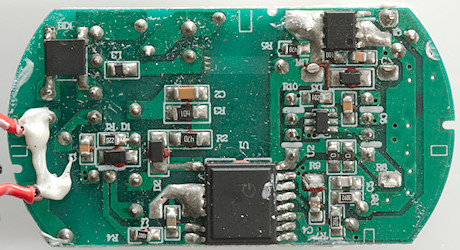
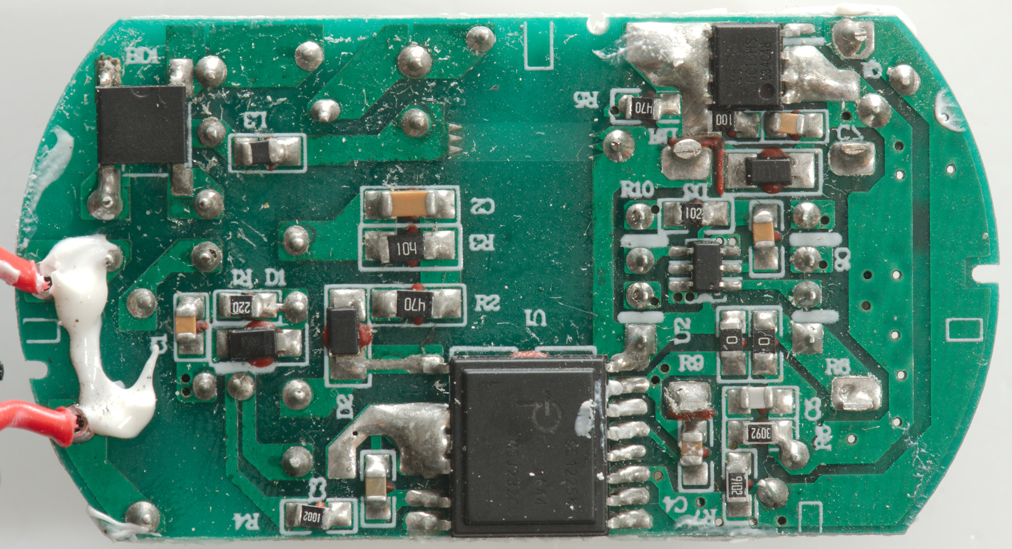
At the input is a bridge rectifier (BD1), most of the other stuff is handled by the main chip (U1: SC1225K), it also controls the synchronous rectifier transistor (Q1:VS6016HS). A auto coding chip (U2: Marked 2634) is placed between the two usb connectors.
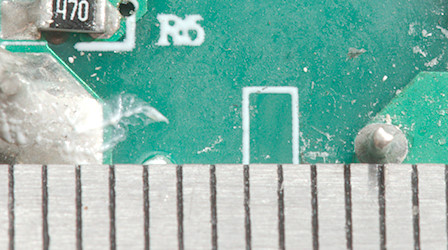
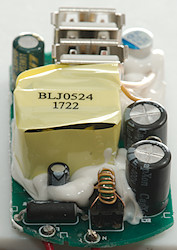
Creepage distance is around 7mm, very good.
Testing with 2830 volt and 4242 volt between mains and low volt side, did not show any safety problems.
Conclusion
For a two port charger the output current is on the low side, except for that it looks fine with auto coding and good safety.
Notes
The usb charger was supplied by Ansmann for a review.
Read more about how I test USB power supplies/charger