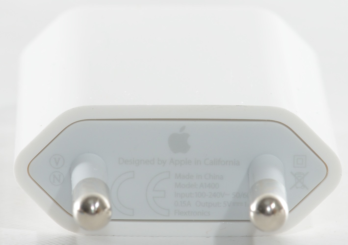
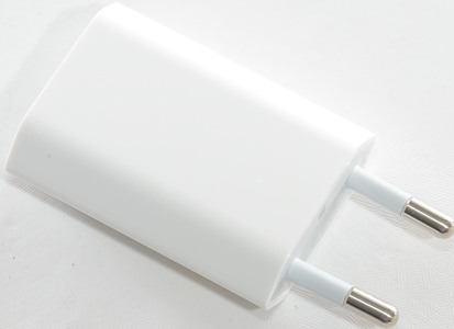
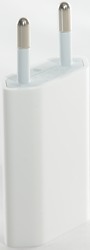
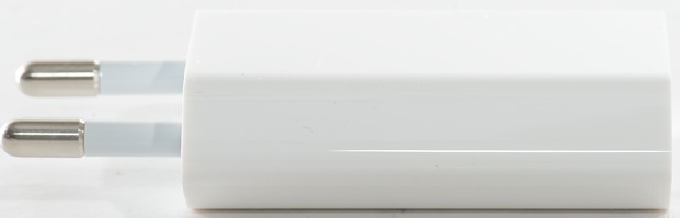
Apple USB power adapter model A1400
Official specifications:
- 5 watt USB power adapter
- Compatible with iPhone and iPod
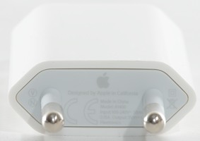
- Output: DC 5V, 1A
- Input: AC 100-240V 50/60Hz
I bought this in the Apple webshop, this way I know it is not a fake.
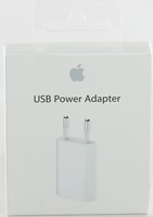
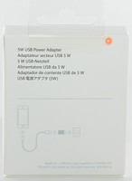
I got this charger in a cardboard box with a picture of the charger on the outside.
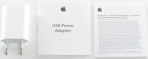
The box contained the charger, manual and warranty card.
Measurements
- Standby power: 0.02 watt
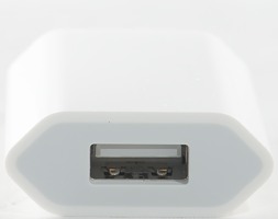
- Output is coded as usb charger (DCP)
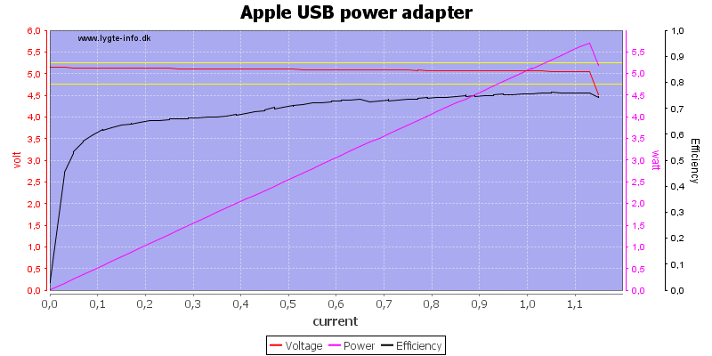
The charger can deliver 1.1A before it shuts down due to overload (Very good).
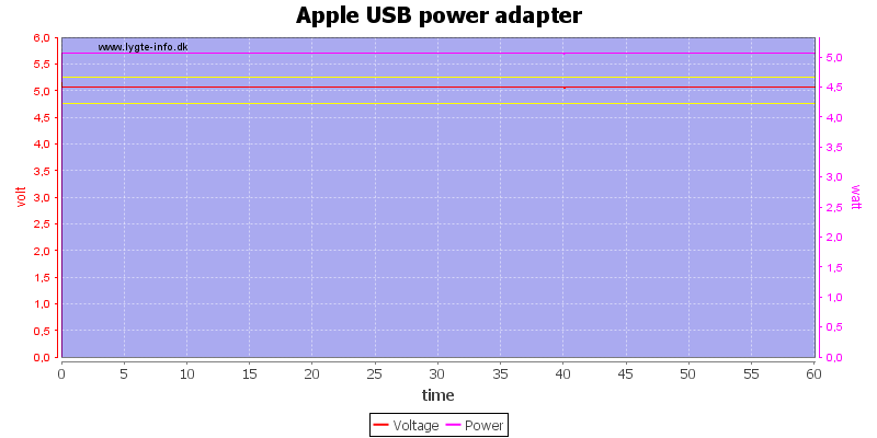
No problem running at 1A for one hour.
The temperature photos below are taken between 30 minutes and 60 minutes into the 1 hour test.
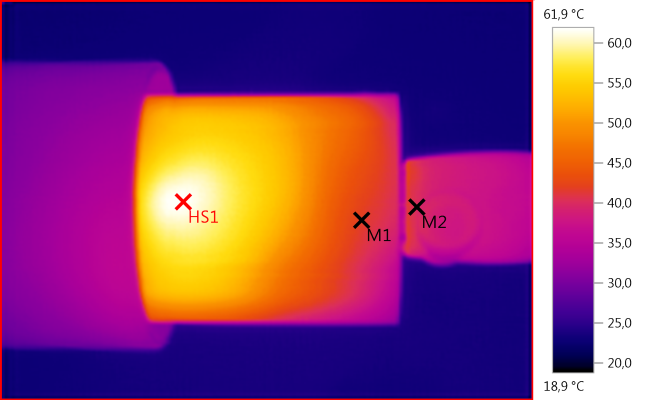
M1: 41,8°C, M2: 40,1°C, HS1: 61,9°C
My guess is that the hot spot is the main controller is.
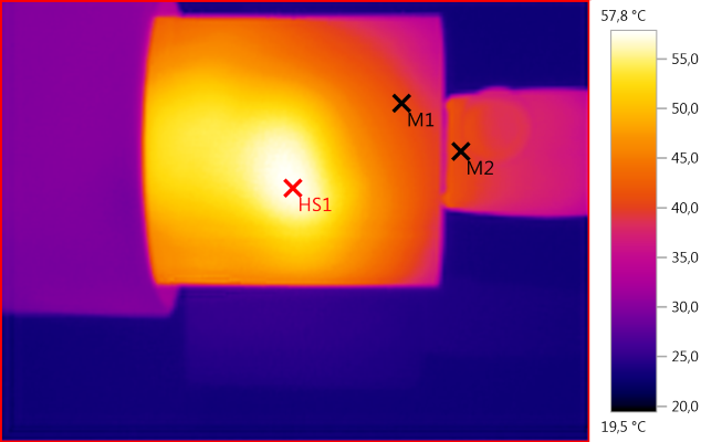
M1: 41,0°C, M2: 40,8°C, HS1: 57,8°C
This hot spot must be the transformer.
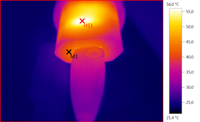
M1: 42,4°C, HS1: 56,0°C
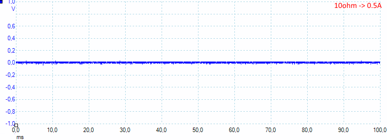
There is not much noise at 0,5A with 8mV rms and 81mVpp
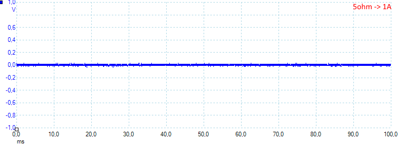
At 1A there is a little bit more noise with 12mV rms and 88mVpp
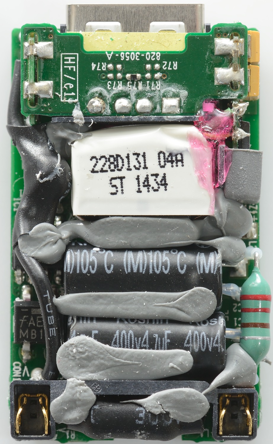
Tear down
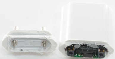
This charger was rather difficult to open, even with the end cut off I could not pull the circuit board out.
This is a very good construction.
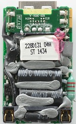
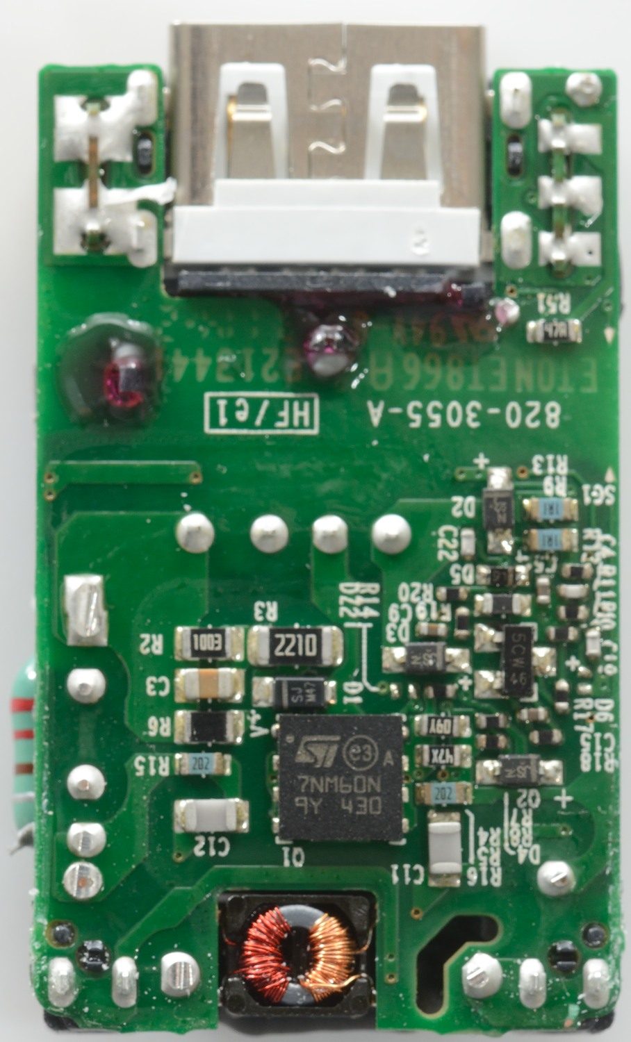
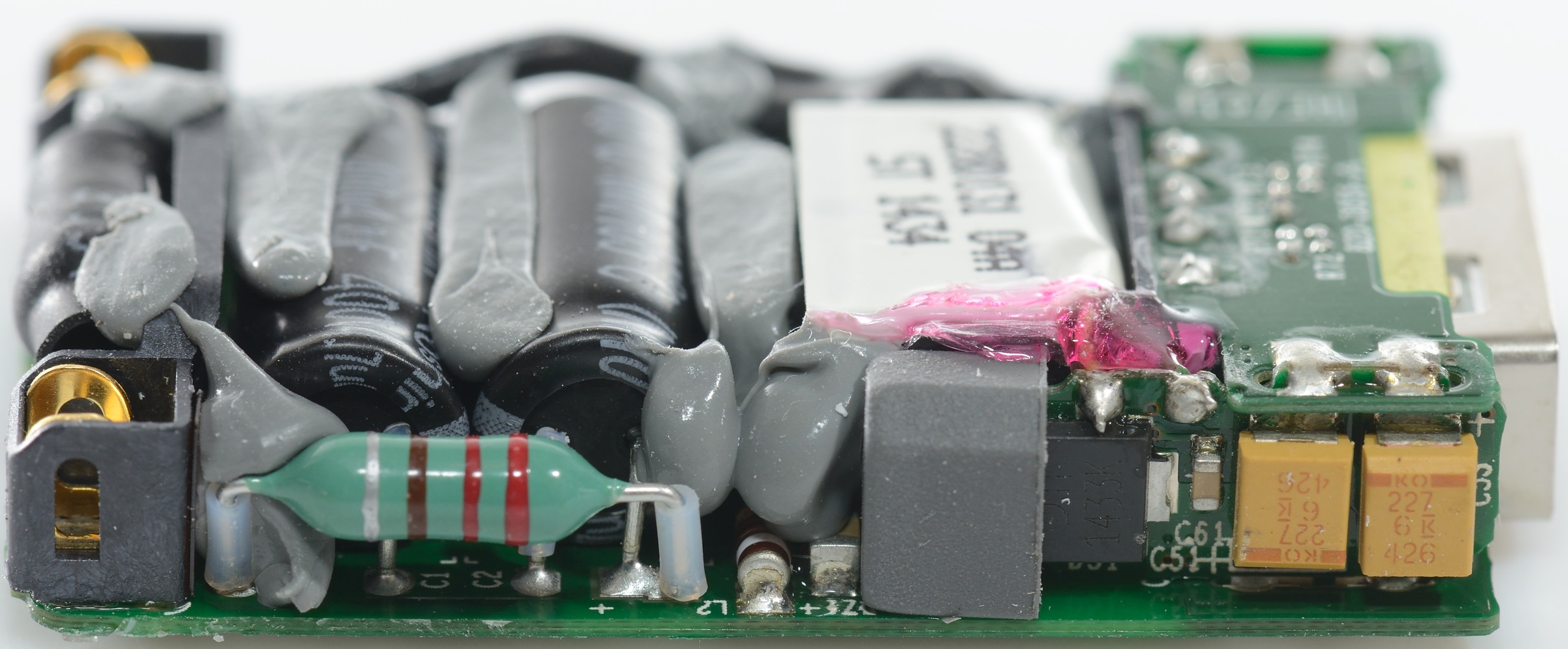
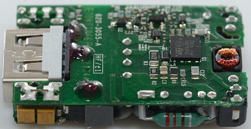
The circuit board is very compact. There is a fuse, common mode inductor, bridge rectifier 105°C capacitors and a chip to control it.

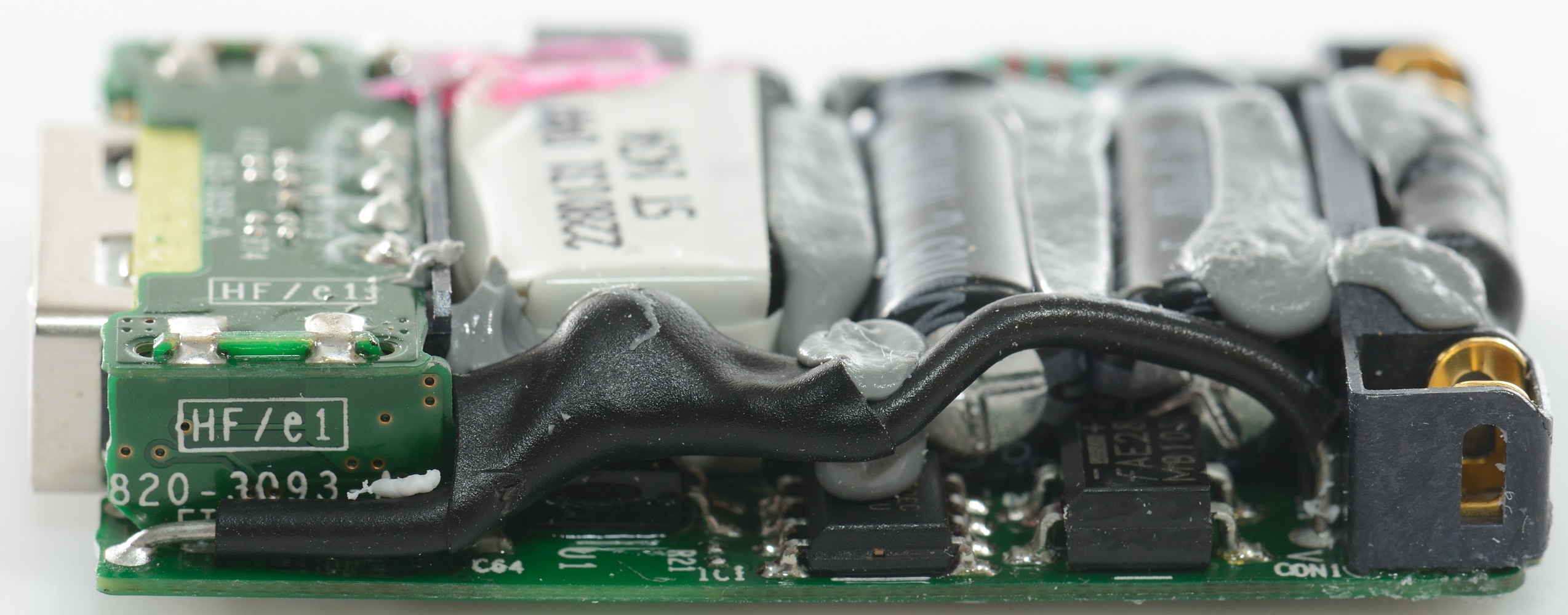
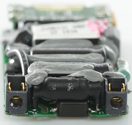
The black connection from mains to low volt side must be the safety capacitor and under the capacitor it looks like a opto coupler to control the output voltage.

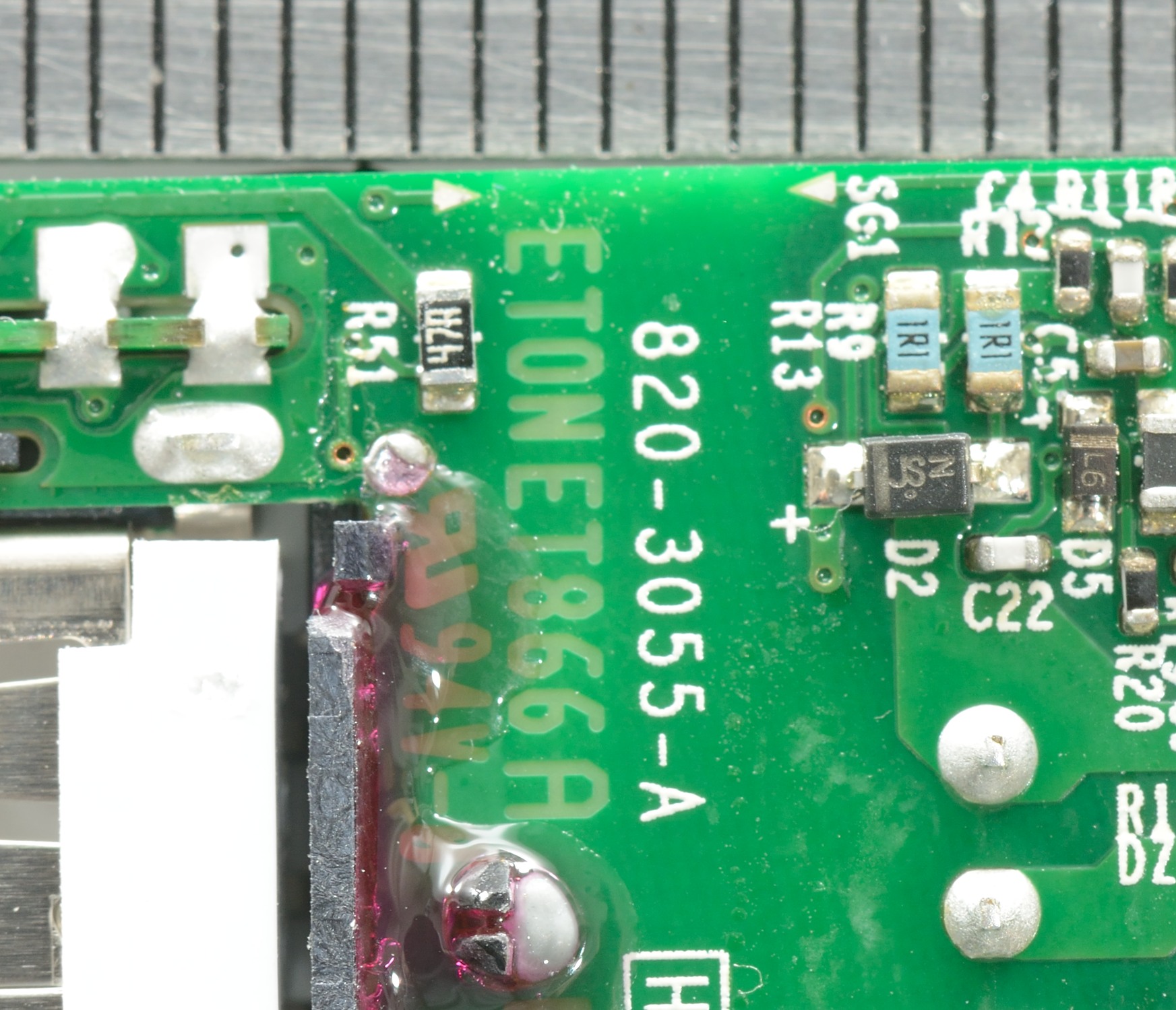
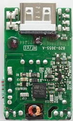
On the small circuit board beside the usb connector is a couple of capacitors and a diode. To isolate the diode from mains there is a rubber cover over part of it.
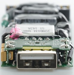
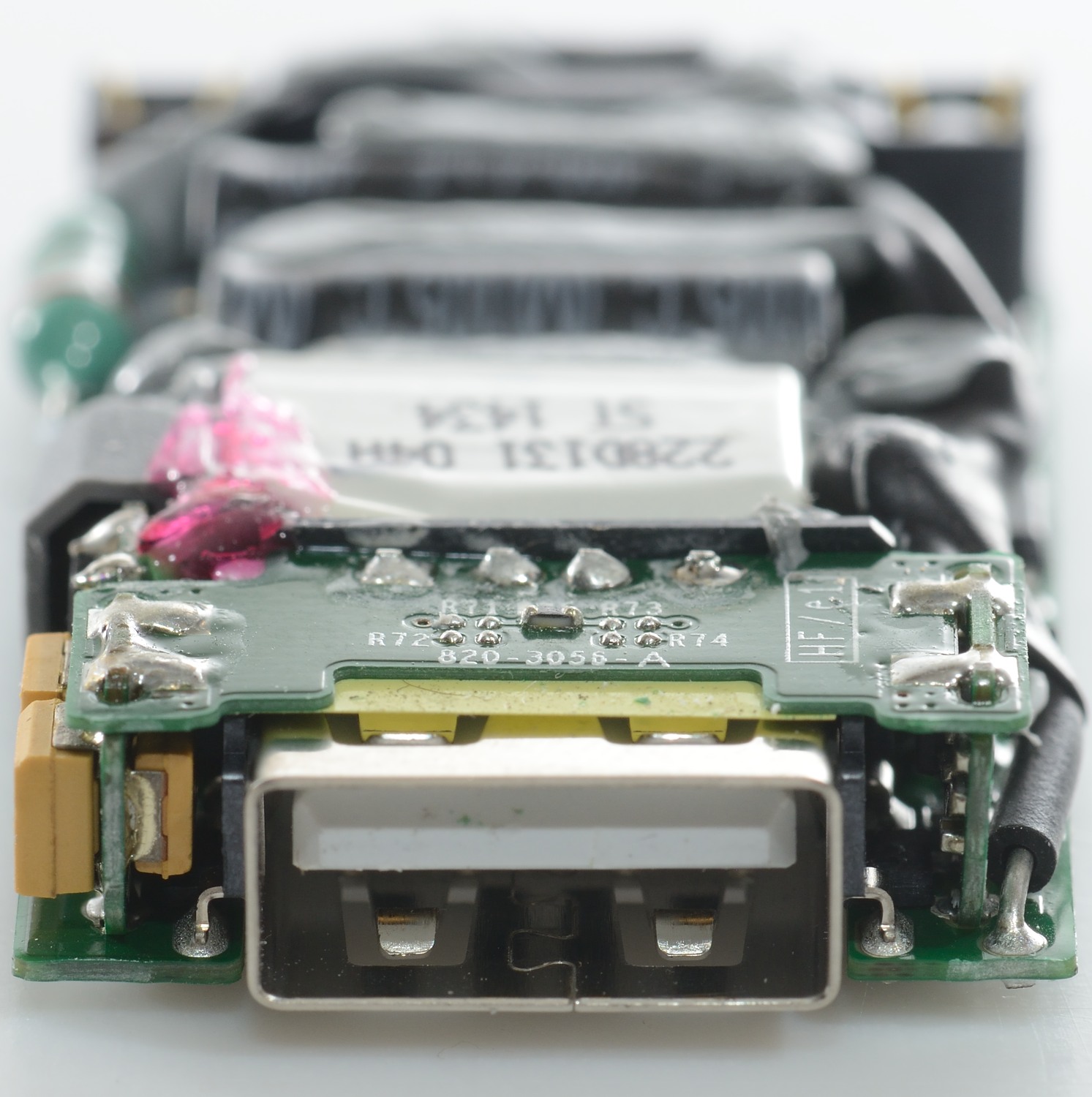
Here it is possible to see all the four circuit boards used in the charger, there is 3 extra circuit board around the usb connector. It must be rather expensive to make it this way.
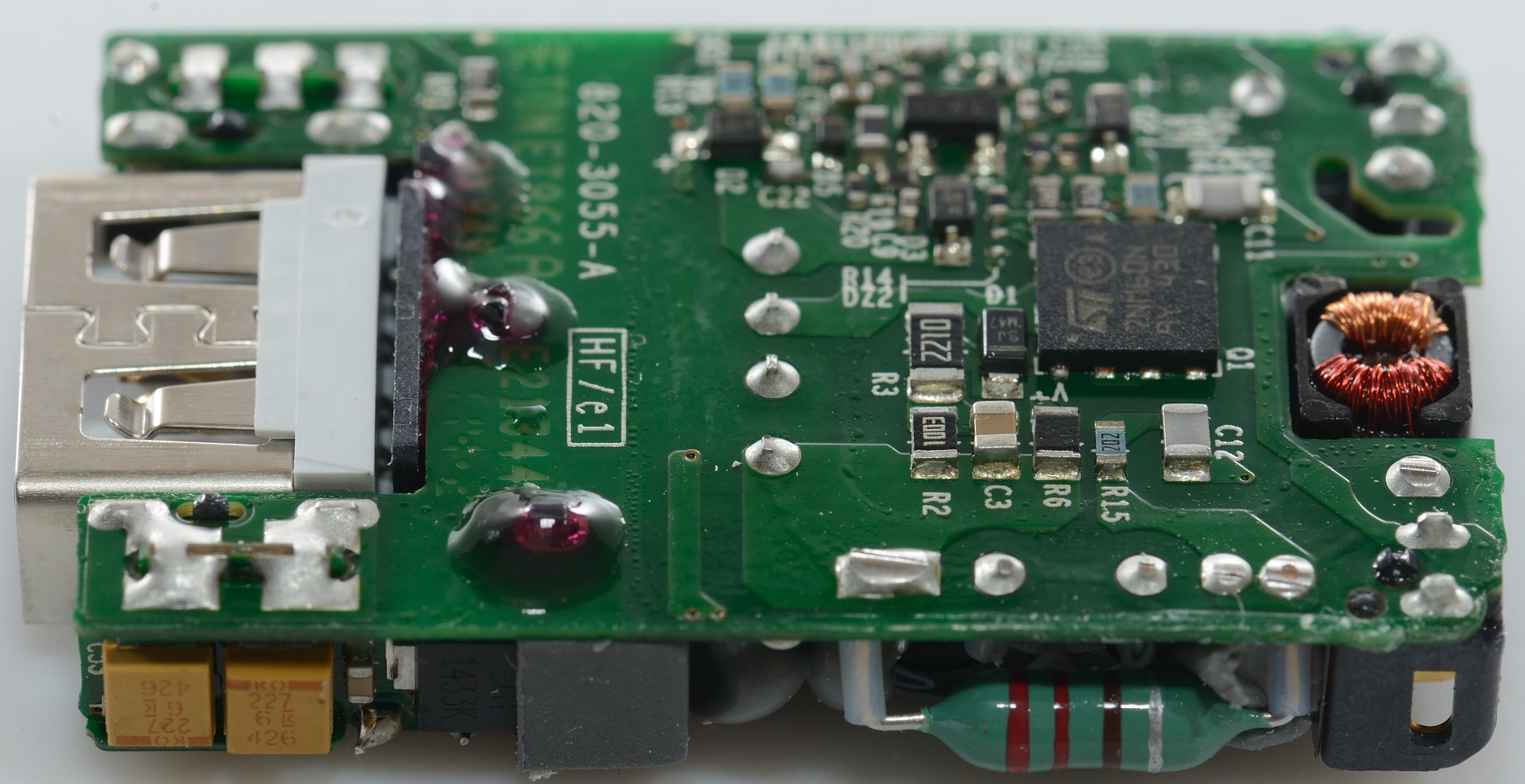
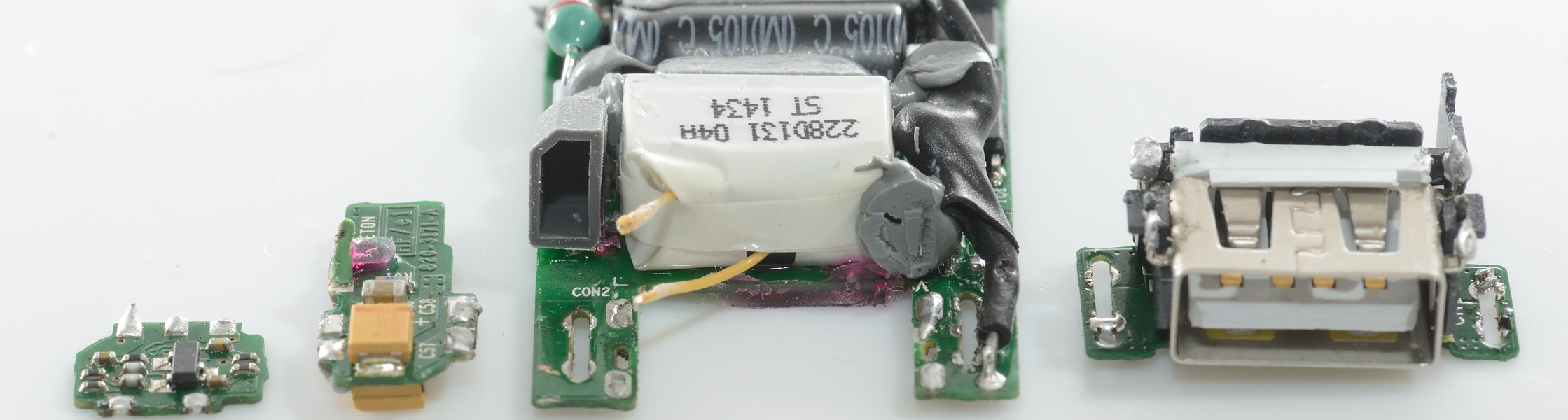
The circuit boards are soldered together, lets take them apart.

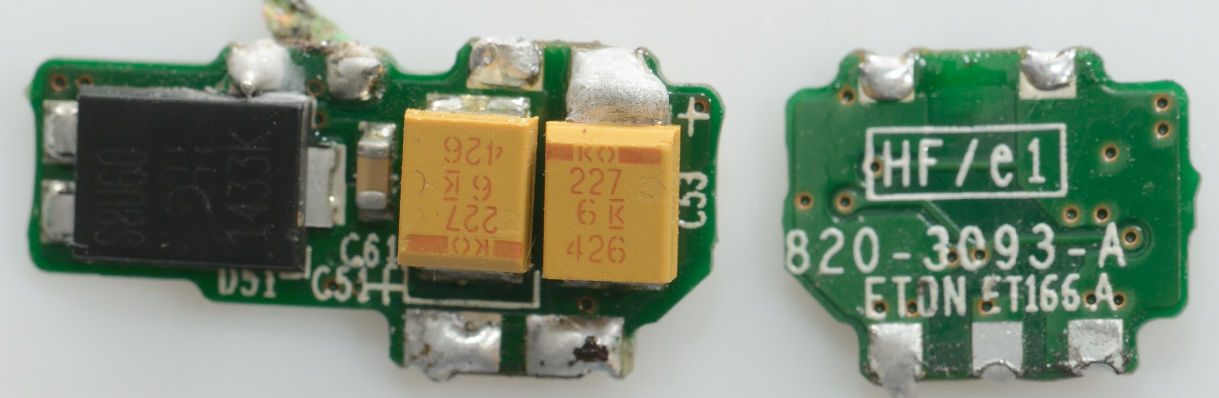
The secondary from the transformer (Two yellow wires) was connected to one of the small circuit boards.
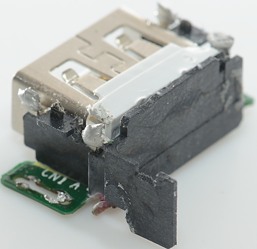
The usb connected has a plastic shield on all sides.
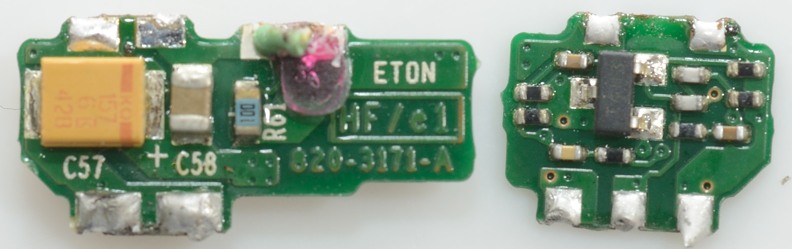
One board has the capacitors, the other has the feedback circuit to control the opto coupler.

Here is more capacitors and the rectifier diode.
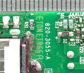
There is a lot of safety distance, but not more than required.
Testing with 2500 volt and 5000 volt between mains and low volt side, did not show any safety problems.
Conclusion
This is a very advanced charger construction, this does also show up in the performance with stable output voltage, overload protection and low noise. It is interesting that Apple has dropped their own special coding in this charger and uses standard usb DCP coding, this means the charger can be used for non-Apple equipment also.
I will call this a very good charger.
Notes
Index of all tested USB power supplies/chargers
Read more about how I test USB power supplies/charger