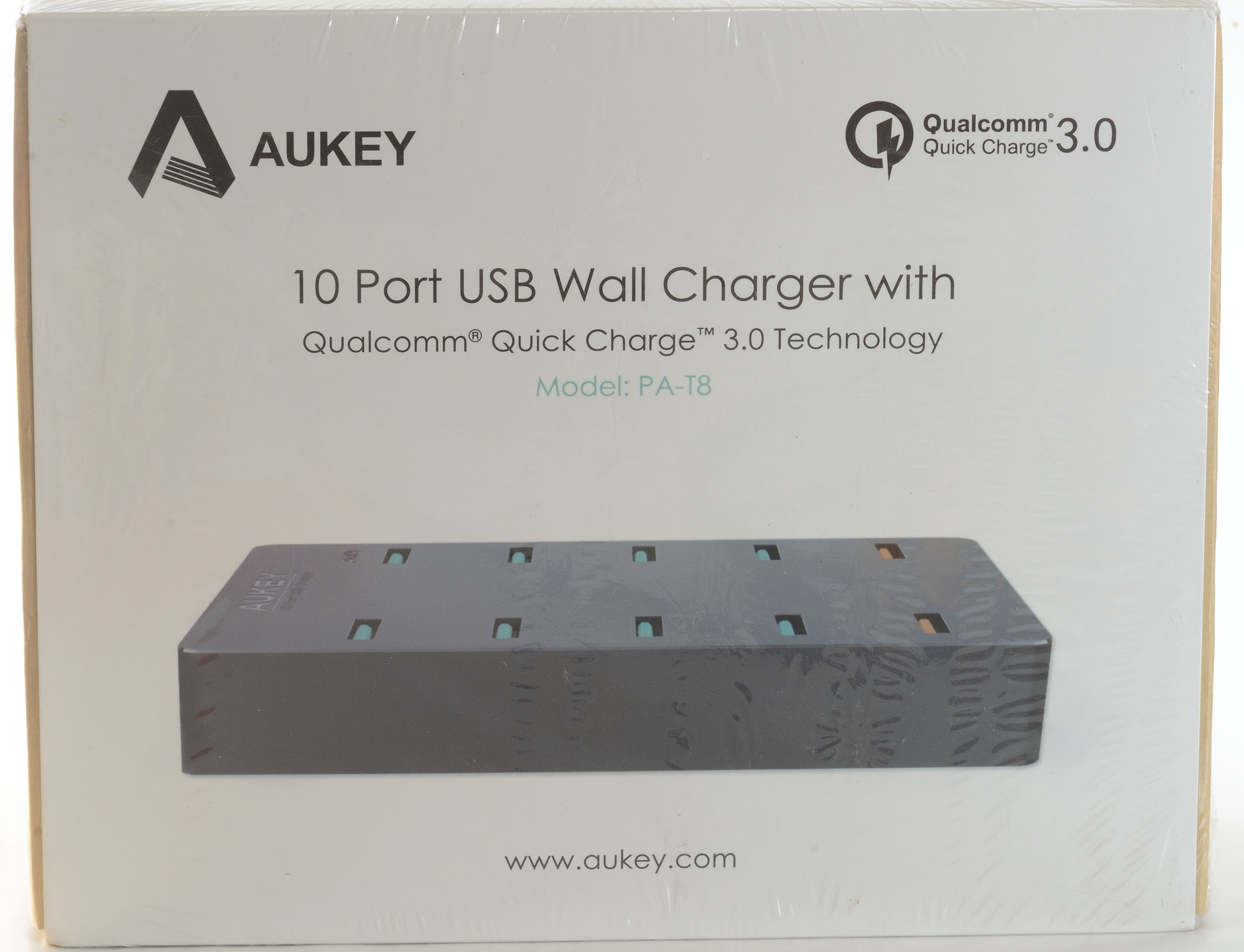
Aukey 10 port wall charger QC3 PA-T8
Official specifications:
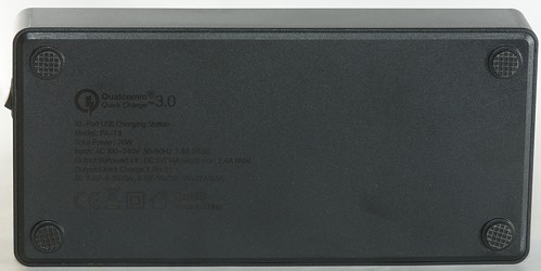
- Model: PA-T8
- Input: AC 100-240V 1.5A
- USB Output(Green Ports): 5V/2.4A, All port maximum 14A
- USB Output (Quick Charge 3.0): 3.6-6.5V/3A, 6.5-9V/2A, 9-12V/1.5A
- Power: 70W
I got it from Amazon dealer AukeyDirect
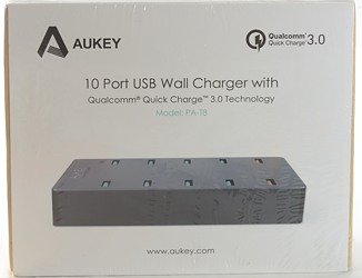
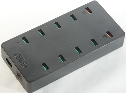
I got this charger in a cardboard retail box.
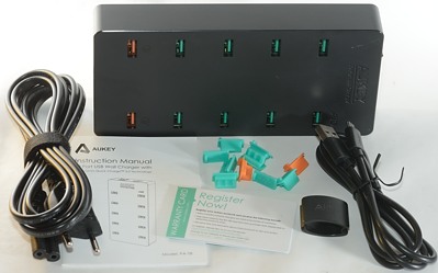
The box contained the charger, a usb cable (Why only one?), a power cable, a instruction sheet, covers for the usb ports, a warranty card and a cable holder.
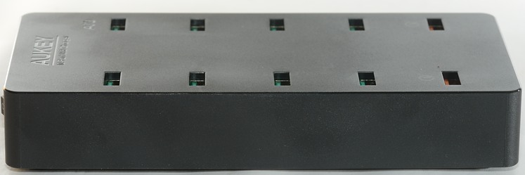
Here I try the covers. It may be a good idea to the cover the usb powers because they are open on top with this charger, but I am not sure loose covers is the best way.
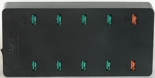
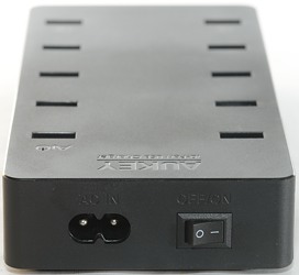
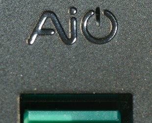
This is one of the few chargers with a power switch. The AiPower logo contains a green led to show that the charger is powered.
Measurements
- Power consumption when idle is 0.55 watt
- All normal usb outputs are in parallel on the plus line, the overload switch is on the minus line.
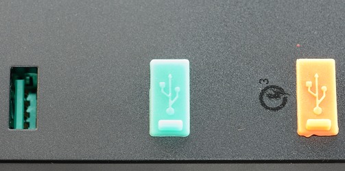
- All normal USB outputs have automatic coding with Apple 2.5A as maximum.
- The two QuickCharge are parallel on the minus line.
- QuickCharge output are usb charger (DCP) and QC2/QC3
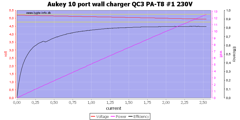
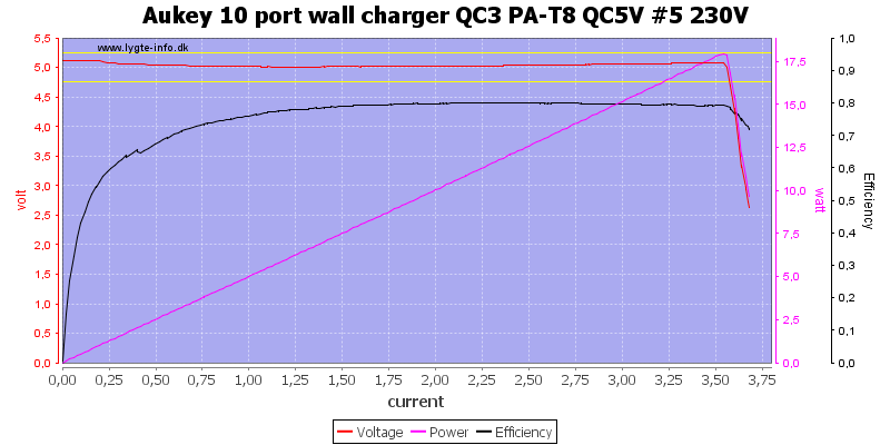
The output is rated for 2.4A and individual over current protection trips at 2.5A, this is very good.

Mains voltage do not affect it.

There is a small variation between usb outputs.
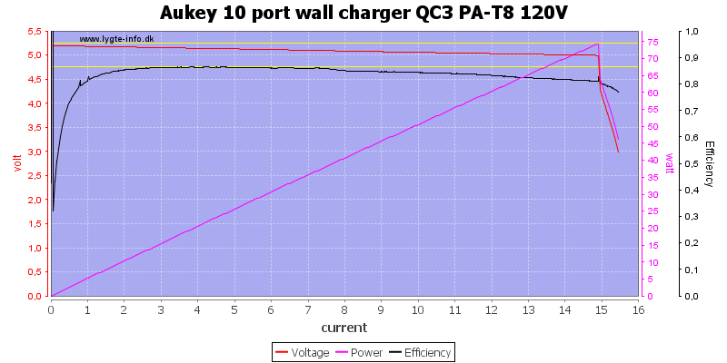
Total current limit is at around 15A
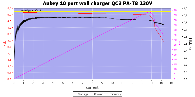
At 230V it drops to 14A
The QC output has a limit of about 3.5A
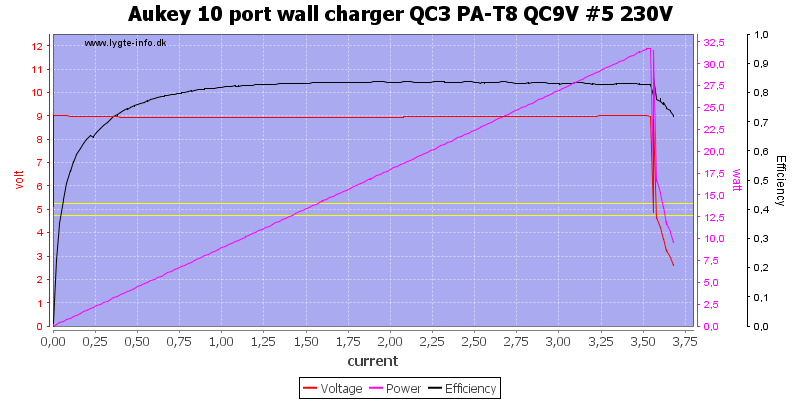
The limit is the same at 9V
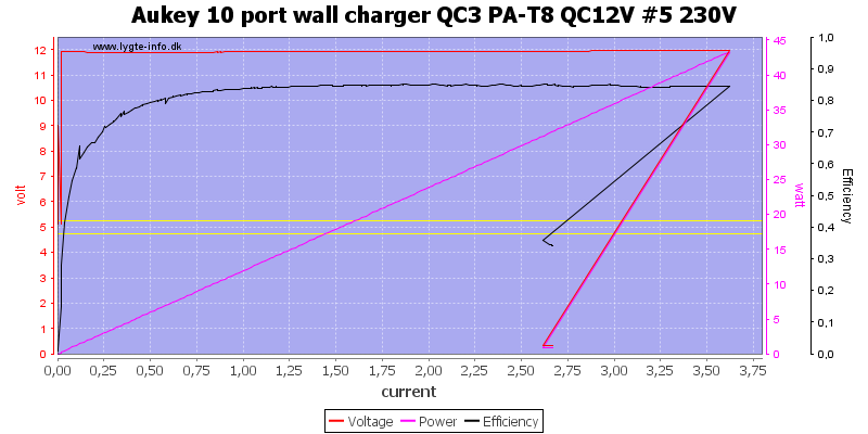
And at 12V.
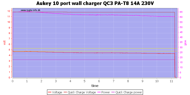
Specifications says I may draw 14A from 5V, in addition to this I draw 1.5A on 12V
The charger could only maintain output for 11 minutes before it shut down, I had to cycle power to get output voltage back.
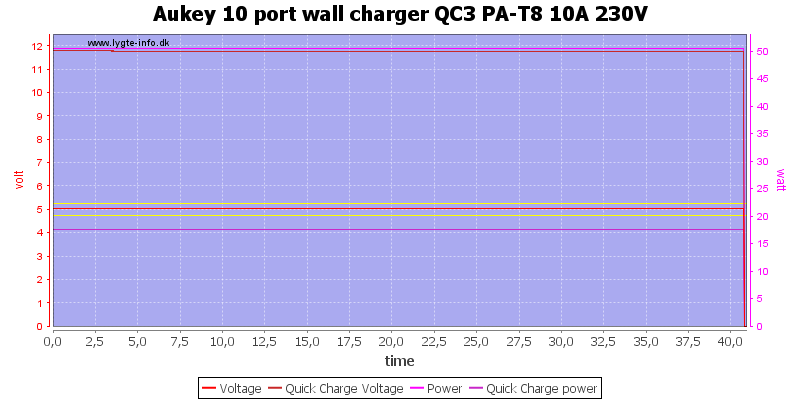
Even at 10A and 1.5A at 12V it could not handle a full hour.
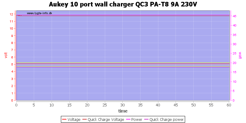
At 9A on 5V and 1.5A on 12V it looks much better, this is 63W (Charger is rated for 70W)
The temperature photos below are taken between 30 minutes and 60 minutes into the one hour test.
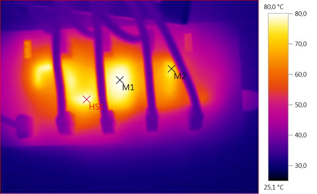
M1: 79,8°C, M2: 73,6°C, HS1: 80,0°C
The 5V rectifier gets very hot (HS1) and also the transformer.
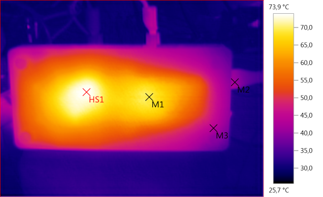
M1: 69,2°C, M2: 41,1°C, M3: 43,3°C, HS1: 73,9°C
Again HS1 is the rectifiers.
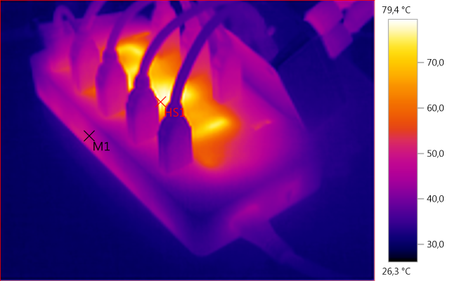
M1: 48,0°C, HS1: 79,4°C
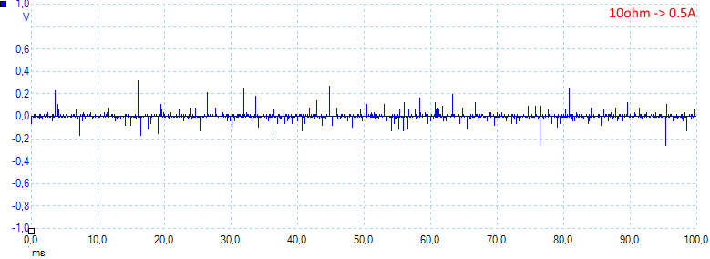
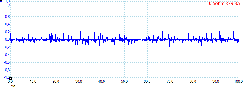
Noise is 16mV rms and 719mVpp, rms noise is very good, but peak noise is a bit high.
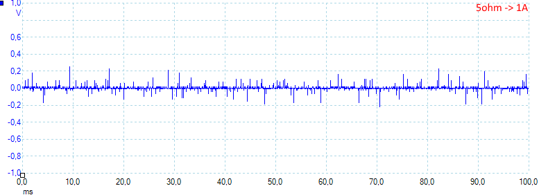
Noise is 17mV rms and 609mVpp
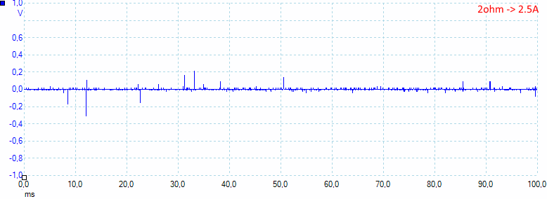
Noise is 16mV rms and 740mVpp
Noise is 30mV rms and 754mVpp
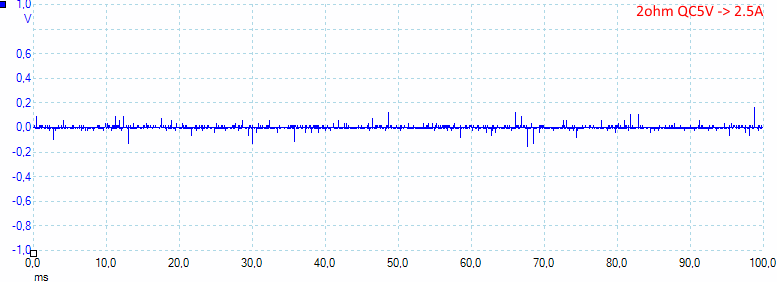
Noise is 11mV rms and 500mVpp
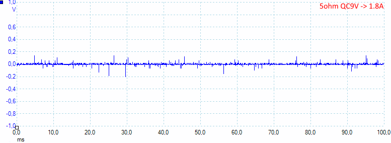
Noise is 8mV rms and 262mVpp
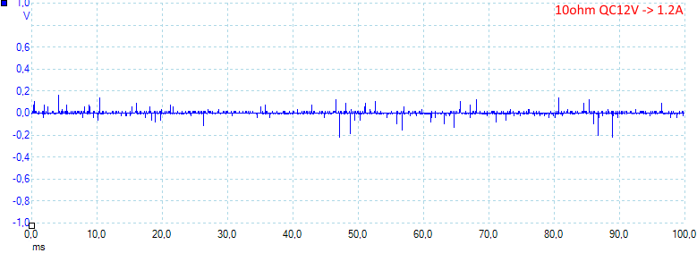
Noise is 9mV rms and 384mVpp, QC has less noise, especially at higher voltages.
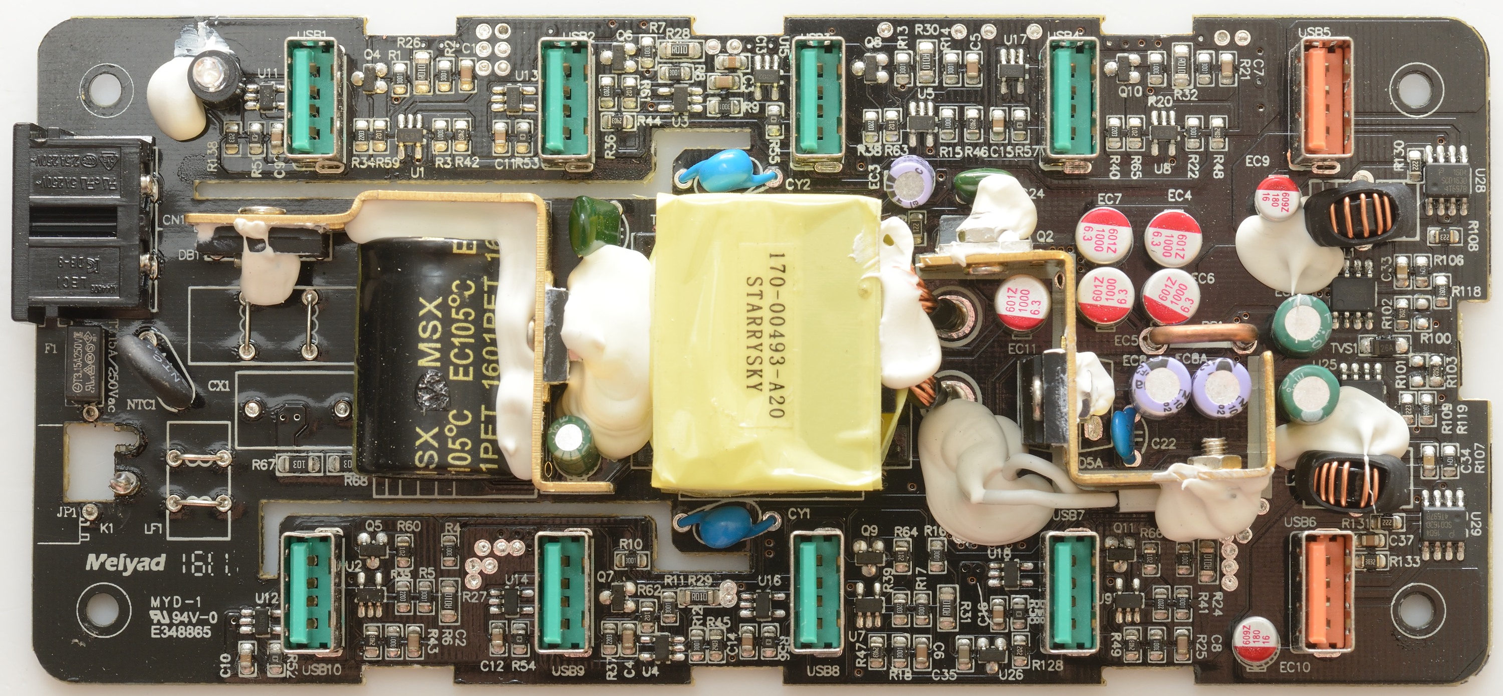
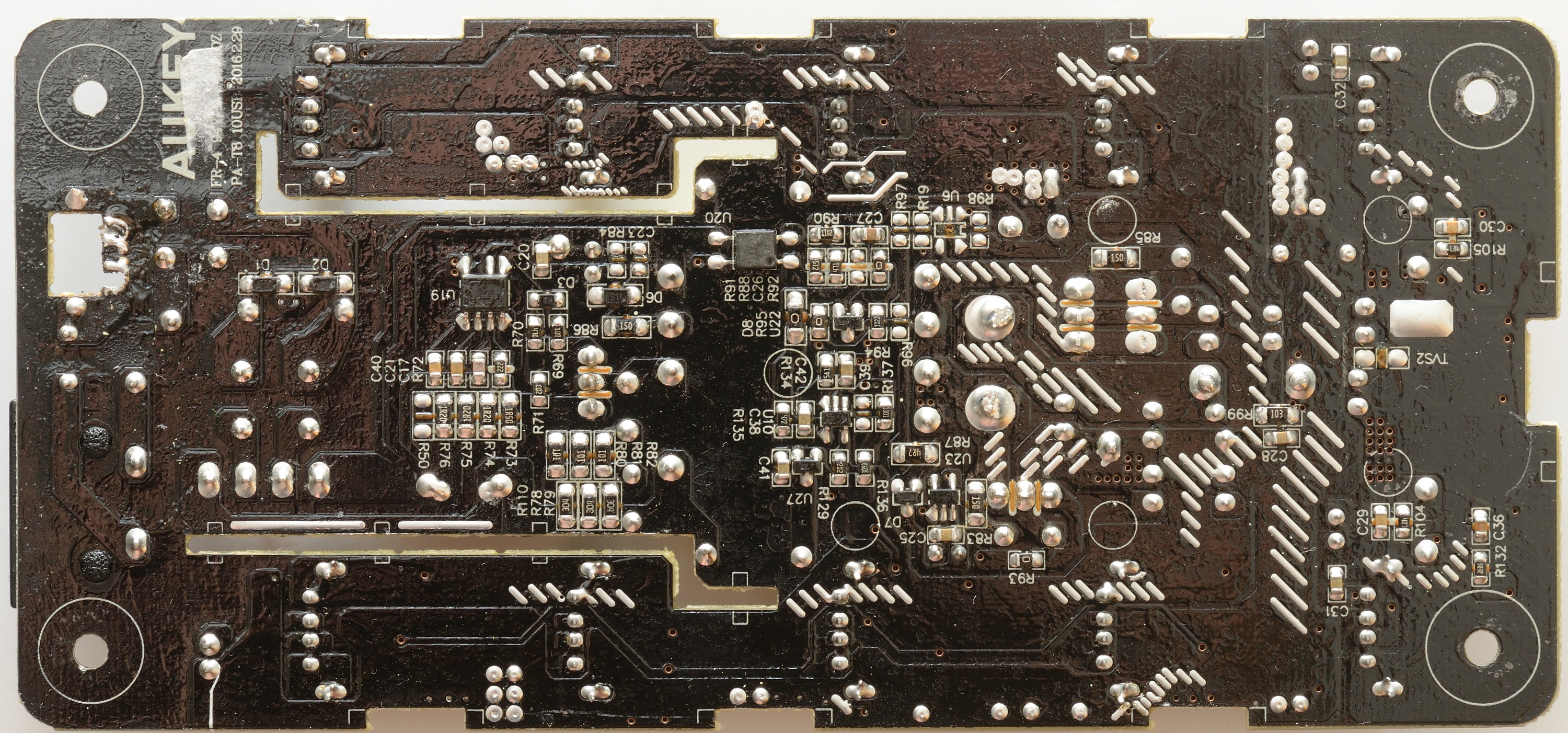
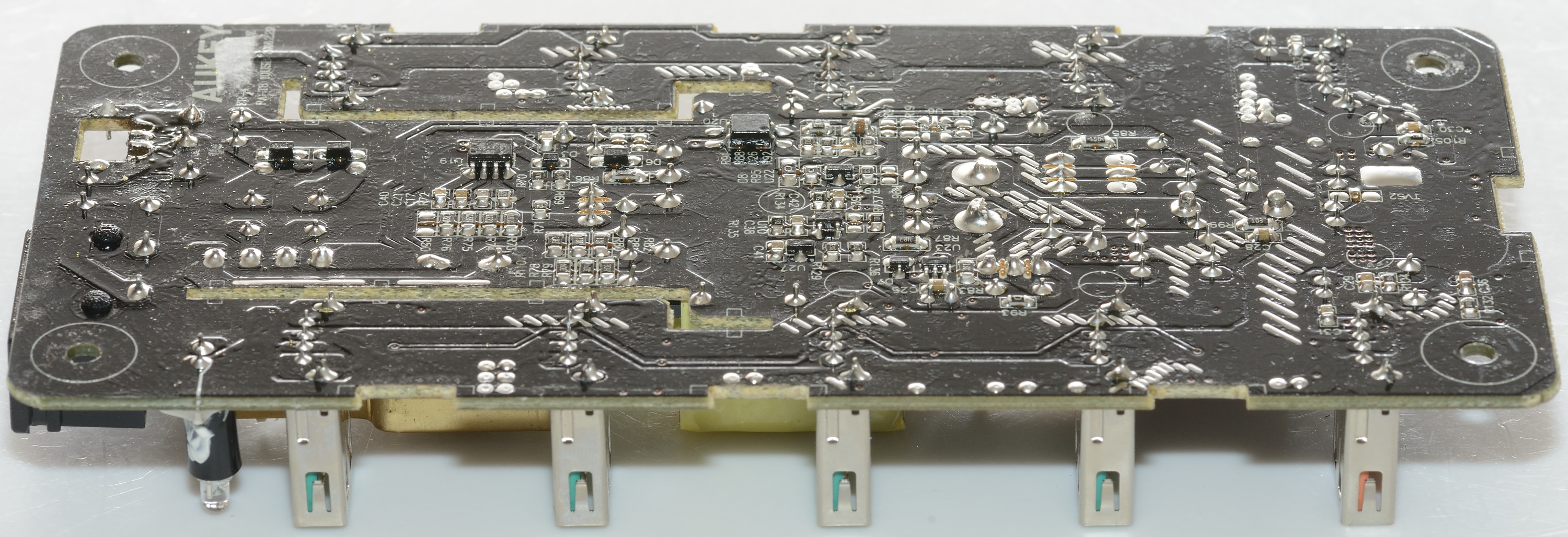
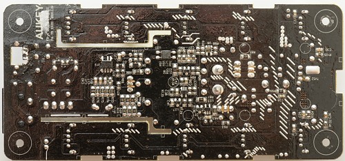
Tear down
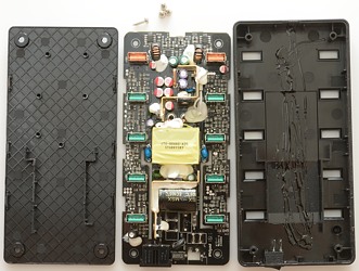
The charger had four screws under the rubber feets and some clips along the edge.

This charger is not just 10 usb ports, but has a lot of parts for each port and it has one obvious omission: The input noise filter is missing, the parts are not mounted.
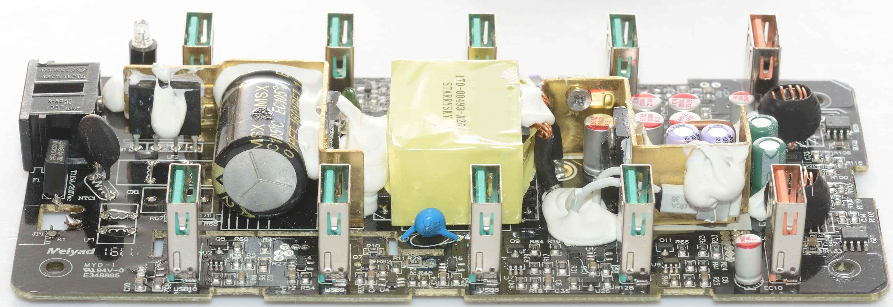
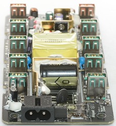
At the input we have a fuse, a inrush current limiter, a bridge rectifier (Mounted on the heatsink) and a switcher transistor. There are two blue safety capacitors, one on each side of the transformer.
One the low volt side there are some very heavy wires comming out of the transformer, two rectifiers on a very small heatsink (For the current rating). There is a thermo sensor mounted on the heatsink. There is a short thick wire on the circuit board, I it used to measure total current consumption.
Between the two orange usb connectors is the two QC circuits. U28 & U29 must be the QC3 controllers, U25 & U2? (RH8603), is the buck controllers, they uses the two inductors.
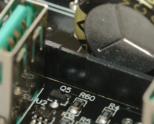
For each normal usb output there is two chips (Autocoding and a OpAmp), a transistor and a R010 resistor. It looks like the current limit it implemented with OpAmp, transistor and a current sense resistor.
U26 is a 431 reference, I wonder what it does here, maybe reference for current limit.

The blue safety capacitors has a lot of marking on it.
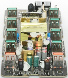
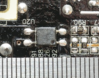
U16 is the switcher controller, U20 is opto feedback. U22 must be the voltage reference.
Looking at the transformer it can be seen that it has more than one secondary on the low volt side. There are two as expected for a charge with both QC and normal usb.
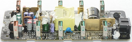
The pins on the transformer are for QC and uses one (space for two) diodes to rectify, the voltage is 15.2 volt.
The two thick wires is used for 5V and uses one transistor to rectify (U23 must be the synchronious rectifier controller).
U10 and U27 is OpAmp and a reference, they are used together with the big shunt to handle the total current limit.

The isolation distance looks to be fine, the only place where parts are a bit close is at the optofeedback, at all other places there is a slot in the circuit board with a plastic shield going through.
Testing with 2830 volt and 4242 volt between mains and low volt side, did not show any safety problems.
Conclusion
The charger cannot deliver full current on both 5V and both QC outputs, when using the QC outputs the current on the 5V outputs will be reduced, due to heat from the rectifiers. In most cases this will not be a problem, very few people need to charge that many devices simultanious at high power.
Two QC outputs can be useful and the risk of running out of normal 5V usb output is very low with this charger, but I am not impressed with the lids. The noise is a bit high.
Notes
Index of all tested USB power supplies/chargers
Read more about how I test USB power supplies/charger
How does a usb charger work?