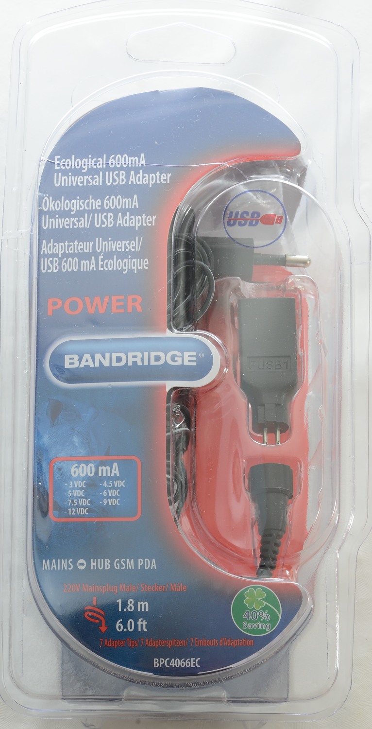
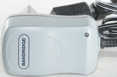
Bandridge BPC4066EC
Official specifications:
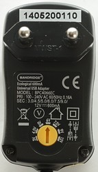
- Input Power: AC 100-240V 50/60Hz
- Output Power: DC 3, 4.5, 5, 6, 7.5, 9, 12V
- Output current: max. 600mA
- Output power: max. 7.2W
- Short circuit protection
- Automatic overload cutoff


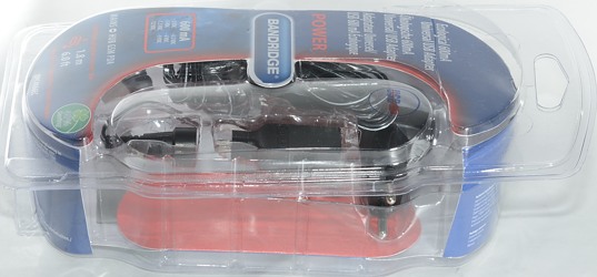
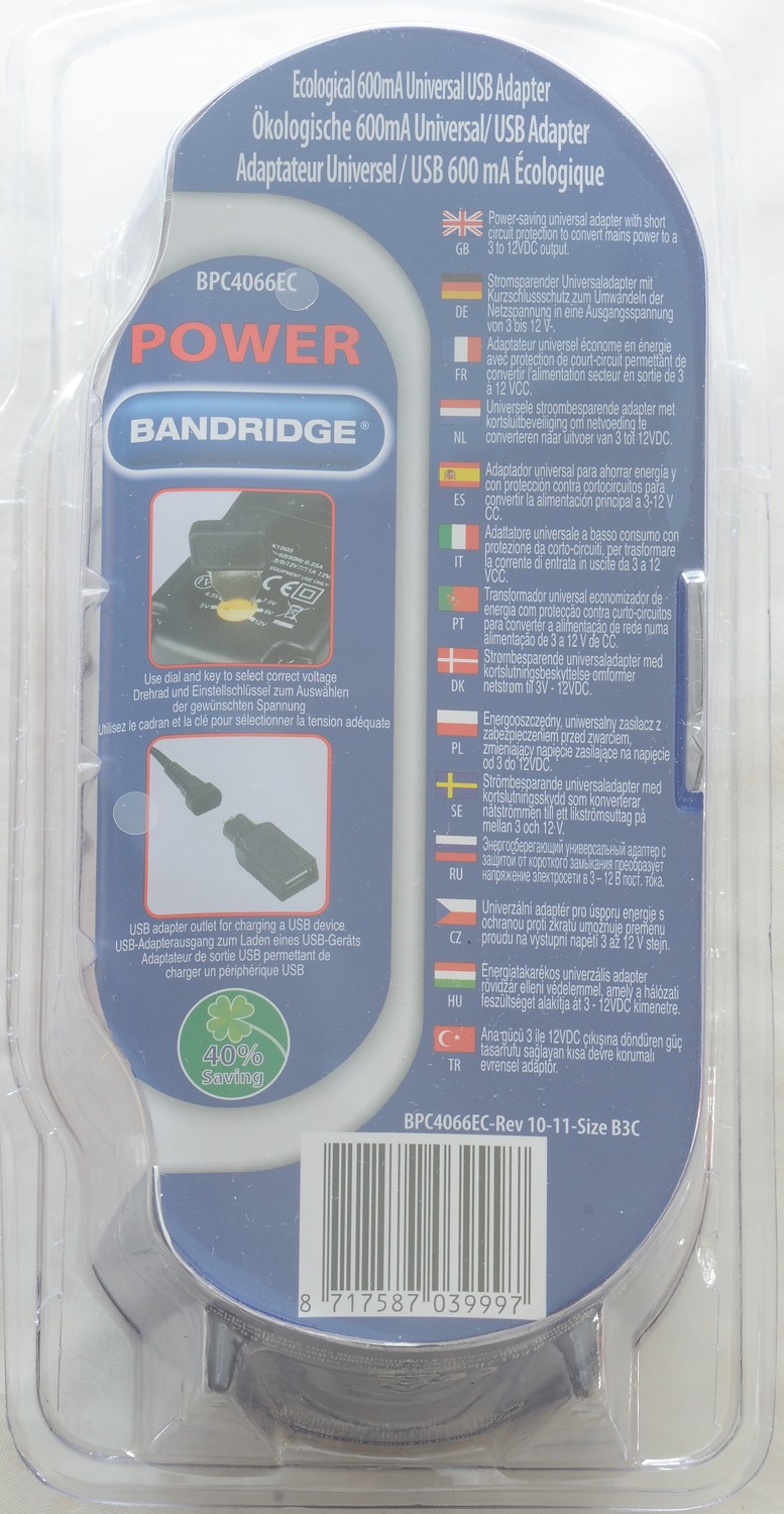
I got it in a plastic box.
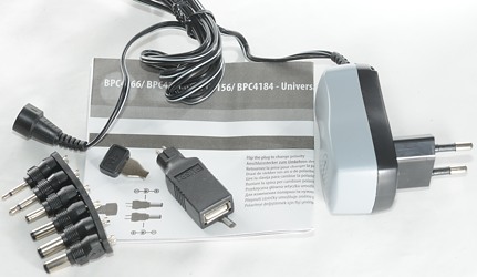
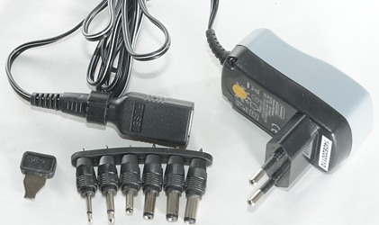
The box included the charger, different connectors and a instruction manual.
It is possible to select many different output voltages: 3V, 4.5V, 5V, 6V, 7.5V, 9V and 12V
When used as a usb power supply it is mandatory to select 5V
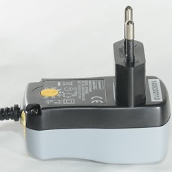
The red led will be on when the charger is powered.
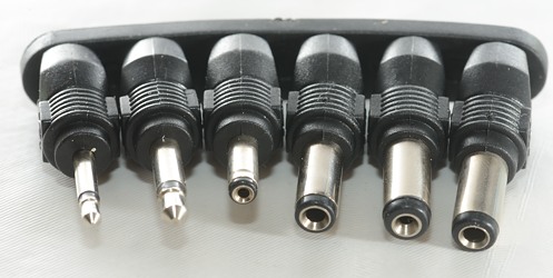
It includes a couple of different plugs:
- USB (It is polarized).
- DC connector 5.5/2.5mm
- DC connector 5.5/1.5mm A 5.5/2.1mm would have been more useful
- DC connector 5/2.2mm None of my stuff uses this size
- DC connector 3.5/1.3mm
- Mini jack 3.5mm
- Micro jack 2.5mm
Measurements
- Power consumption when idle is 0.1 watt
- Usb outputs are coded as Apple 2.1A
- Weight: 70.5g without accessories
- Size: 68.3 x 79.0 x 38.5mm
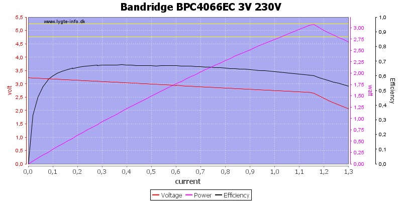
At 3V it can deliver twice the rated current, the voltage will drop probably due to the cable.
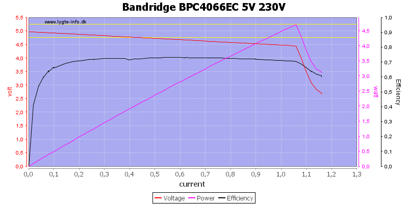
The 5V output can easy deliver the rated 600mA, it will first drop above 1A.
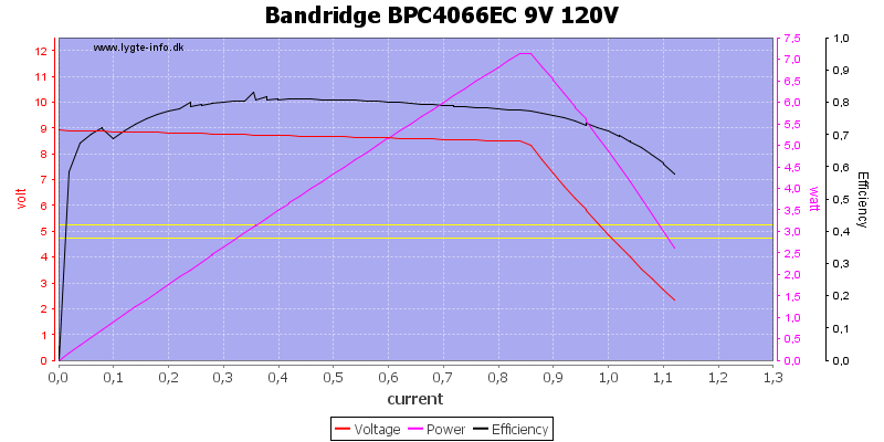
At 9V it will drop at 800mA.
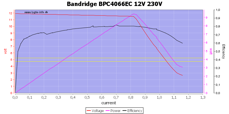
At 12V it can deliver more than rated power and more than rated current.
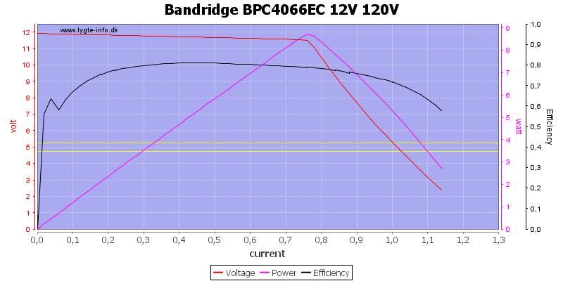
It will also work with 120VAC.
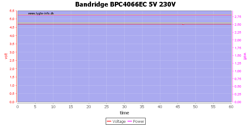
No problems running one hour at 5V 600mA (rated current), it is well below maximum power for the supply.
The temperature photos below are taken between 30 minutes and 60 minutes into the one hour test.
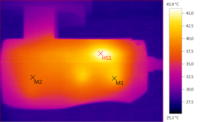
M1: 41,4°C, M2: 37,8°C, HS1: 45,9°C
HS1 is the rectifier diode

HS1: 35,3°C
Generally the charger is rather cool, but it is also running way below rated power.
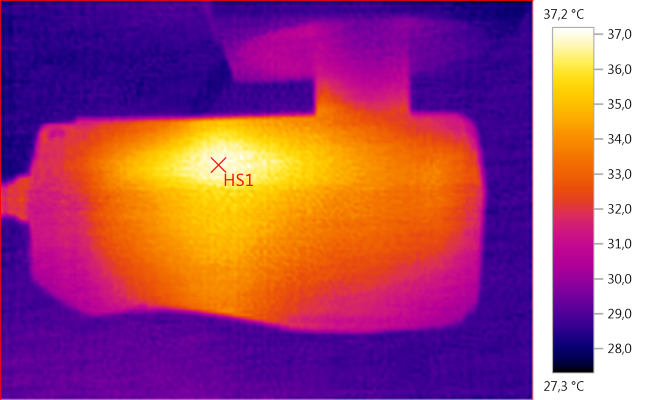
HS1: 37,2°C
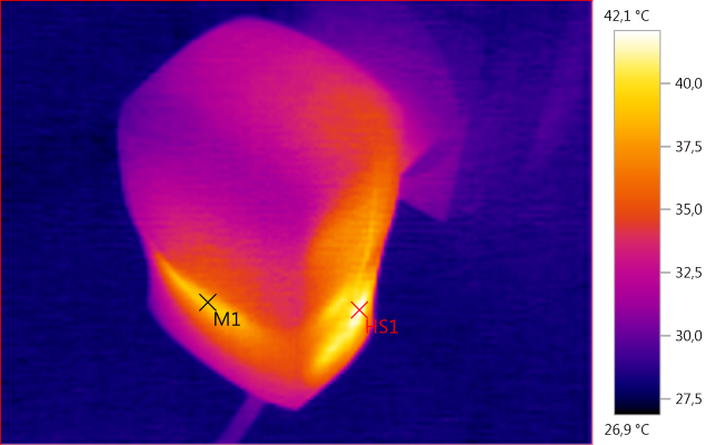
M1: 38,8°C, HS1: 42,1°C
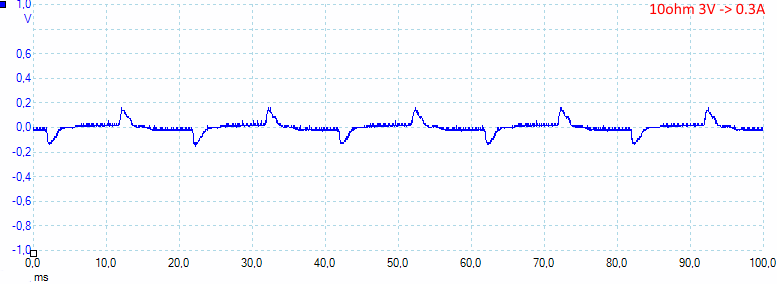
At 3V 0.5A the noise is 44mV rms and 318mVpp. The regulation cannot really work smoothly at this low load.
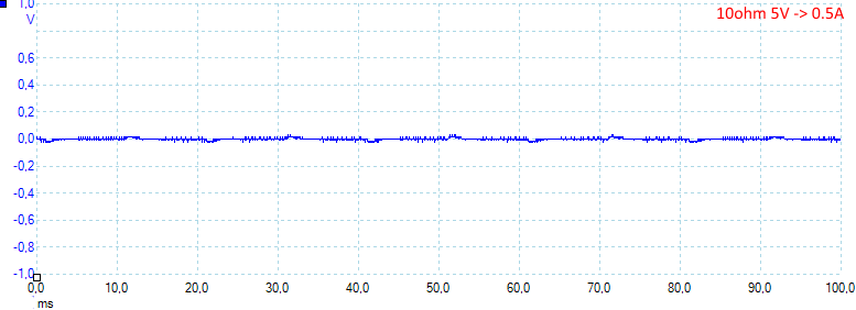
At 5V 0.5A the noise is 6mV rms and 43mVpp. Here the noise is very low.
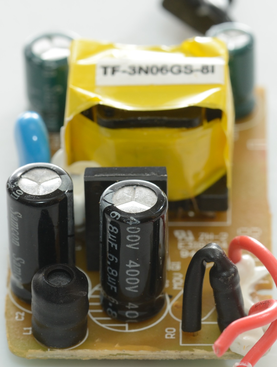
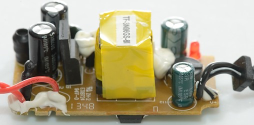
Tear down
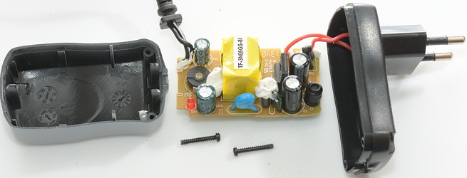
Removing two screws and it was open.
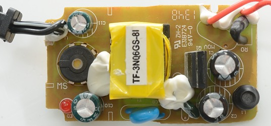
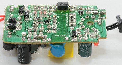
On this side there is a fusible resistor at the input (R0), an inductor between the two mains capacitors (L1), a switching transistor (Q1). There is also a blue safety capacitor.
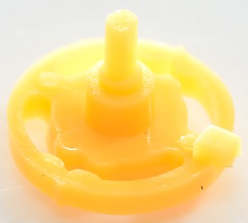
On the low volt side is a rotary switch (MS: for voltage selection) and a led.
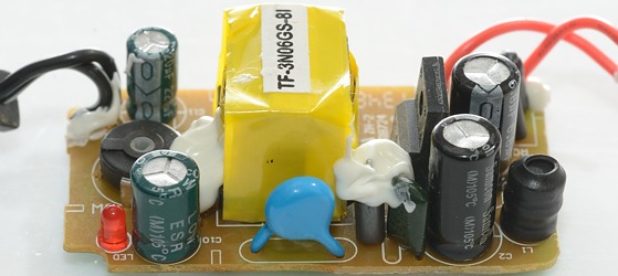
Under the white stuff a ferrite bead can be seen, it works as an inductor. Beside the ferrite is the blue safety capacitor.

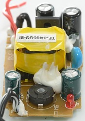
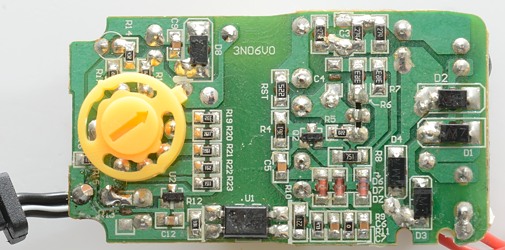
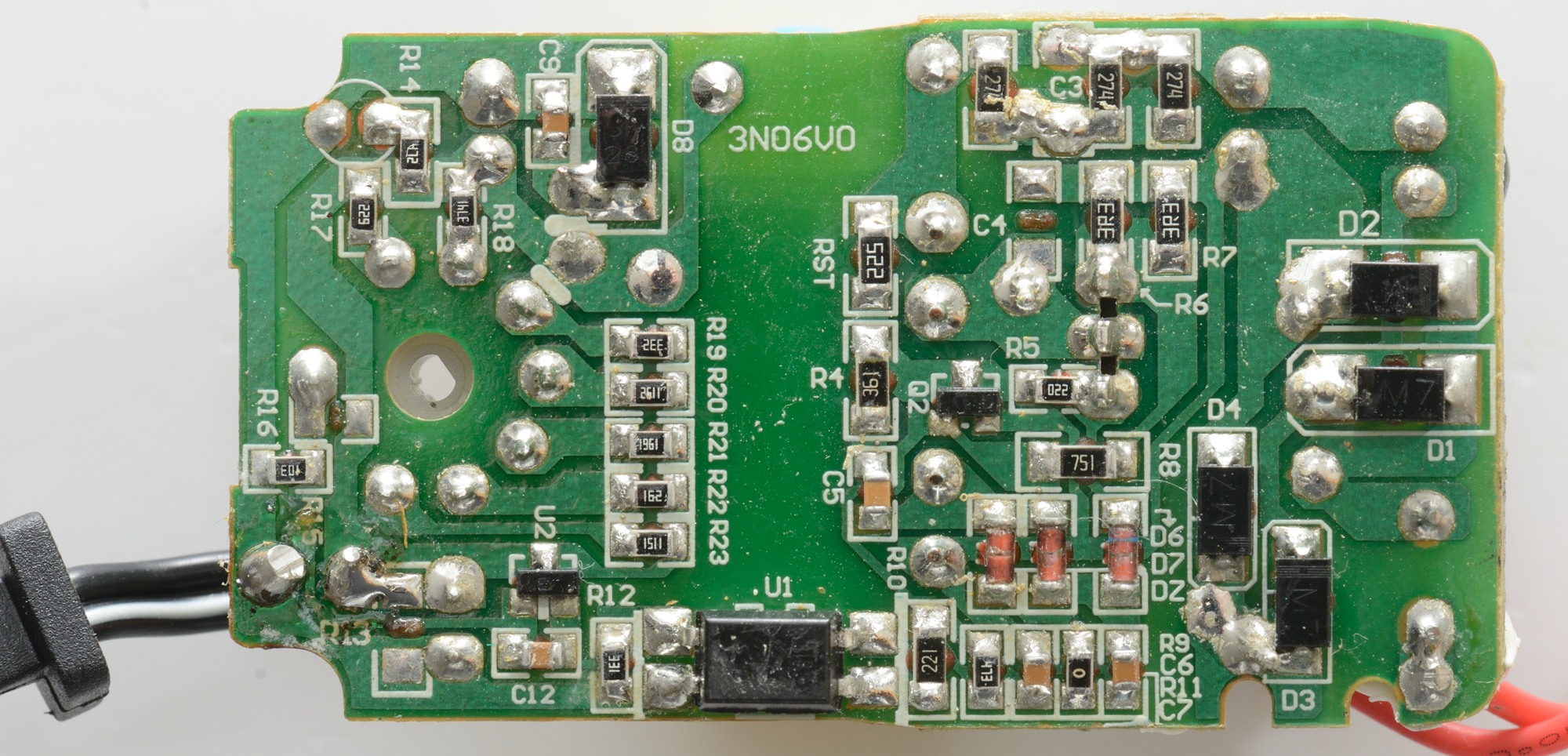
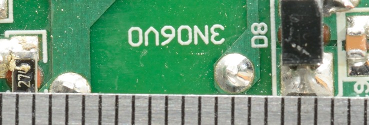
The bridge rectifier is made by four diodes (D1..D4), there is no mains switcher IC, but instead only a transistor (Q2).
Due to the variable voltage it need opto feedback and a reference (U2). The rotary switch will switch between a couple of resistors (R19..R23). The rectifier diode is on this side (D8).

I did not open the usb connector, but it must have a couple of resistor in it to do the coding.
Safety distance looks good.
Testing with 2830 volt and 4242 volt between mains and low volt side, did not show any safety problems.
Conclusion
This is a cheap universal power supply, it works and is safe (for humans, not for equipment). The universal part means that it can deliver the correct voltage and polarity for a lot of small items, but it can also deliver the wrong voltage and polarity, depending on the switch position and how the connector is plugged into the cable.
The coding on the usb output is rather misleading.
Notes
Charger was supplied by Pro backup (probackup.nl)
Index of all tested USB power supplies/chargers
Read more about how I test USB power supplies/charger
How does a usb charger work?