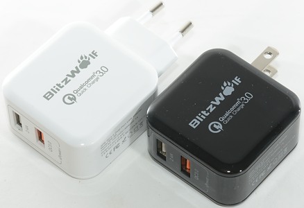
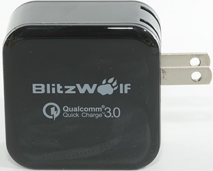
BlitzWolf 30W QC3.0 Dual-Port USB Adapter BW-S6
Official specifications:
- Brand: BlitzWolf®
- Model: BW-S6
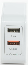
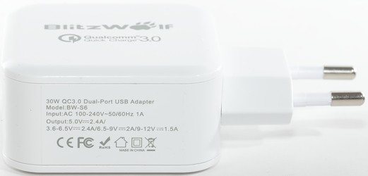
- USB Port: 18W(Max) QC3.0 Port + 12W(Max) 2.4A Port
- Total Power: 30W (Max)
- Input: AC 100-240V~50/60Hz 1A
- Output: 2.4A Port: 5V/2.4A (Max), QC3.0 Port: 3.6-6.5V/2.4A 6.5-9V/2A 9-12V/1.5A (Max)
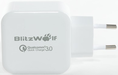
- Size: 53X 53X25 mm / 2.09 X 2.09 X 0.98 inch
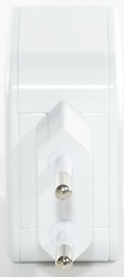
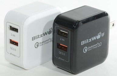
- Color: White, Black
- Weight: 100g±10g
- Certification: CE,FCC,RoHS,Qualcomm QC3.0
I got it from Banggood

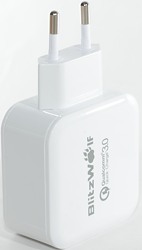
Blitzwolf uses a brown cardboard box without much text on the outside. The EU version is in the large box.
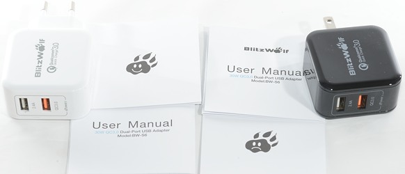
The box contained the charger, instruction sheet and a note.
Measurements
- Power consumption when idle is 0.4 watt at both 120VAC and 230VAC
- Lowest QC3 voltage is 3.5V
- QC output is QC and auto coded with up to Apple 2.4A
- 2.4A output is auto coded with up to Apple 2.4A
- The charger has a blue led inside, that is shining out through the usb connectors.
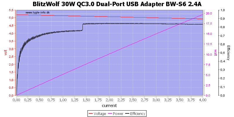
There is no obvious overload protection on the 2.4A output.
The efficiency curve is a bit interesting, why does it take a jump at about 1.4A?

At 120VAC the improvement in efficiency happens at 0.75A.
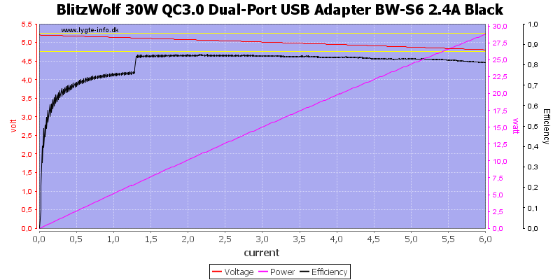
Most test is done with the white EU adapter, but I did the above curve to see how much difference there was between the two adapters. It looks to be fairly minor.
I also increased the maximum current to look for a over current limit, but did not find one.
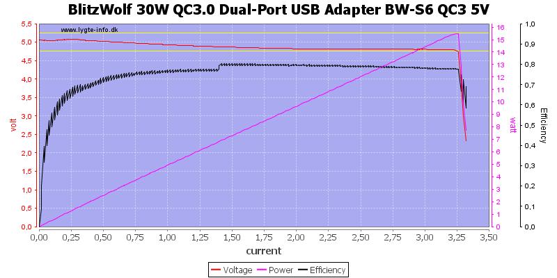
QuickCharge must use a seperate converter and it has a overload limit.
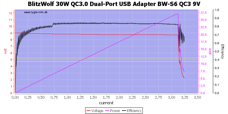
QC is supposed to deliver less current at 9V, but id can deliver the same current. I did this test at 230VAC, but the efficiency jump has moved down.
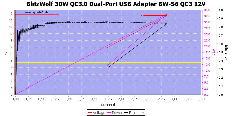
At 12V the over current limit has moved a bit down, but the adapter can provide much more power than rated.
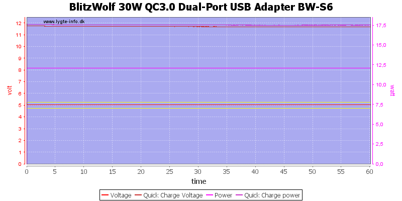
Loading both QC and 2.4A output with rated power for 1 hour works fine.
The temperature photos below are taken between 30 minutes and 60 minutes into the one hour test.
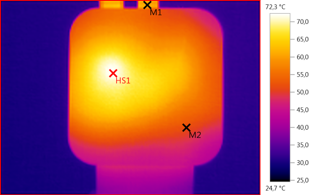
M1: 61,1°C, M2: 51,7°C, HS1: 72,3°C
HS1 is the QC diode D5.
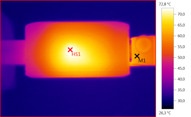
M1: 60,0°C, HS1: 72,8°C
HS1 is probably the rectifier transistor.
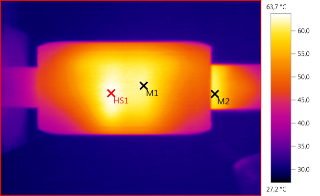
M1: 61,6°C, M2: 60,2°C, HS1: 63,7°C
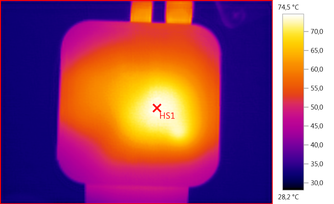
HS1: 74,5°C
HS1 is the transformer.
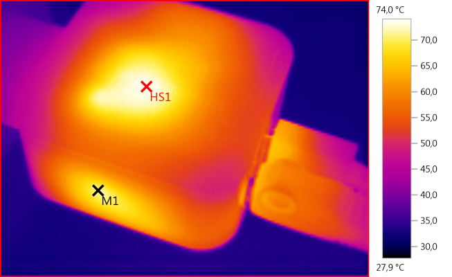
M1: 70,9°C, HS1: 74,0°C
HS1 is the transformer and M1 is the rectifier transistor.
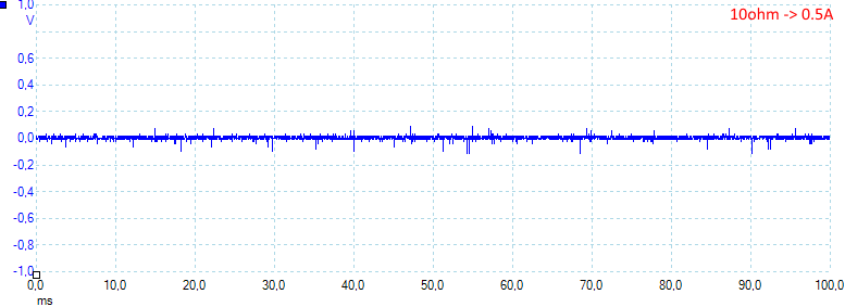
At 0.5A the noise is 11mV rms and 260mVpp
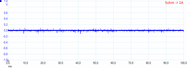
At 1A the noise is 15mV rms and 290mVpp
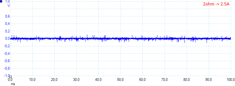
At 2.5A the noise is 19mV rms and 310mVpp
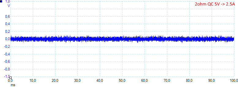
At 5V and 2.5A on QuickCharge the noise is 34mV rms and 270mVpp
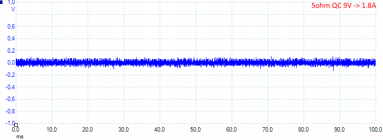
At 9V and 1.8A on QuickCharge the noise is 31mV rms and 220mVpp
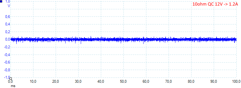
At 12V and 1.2A on QuickCharge the noise is 24mV rms and 165mVpp
Tear down
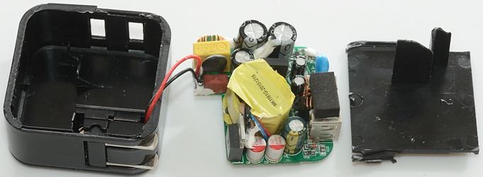
I could not break the glue with a vice or mallet, I had to cut it open, with the square shape it was fairly easy.
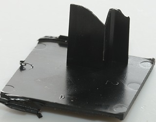
This piece of plastic has a shield on it. This shield goes all the way between the two sides of the charger, through the slot in the circuit board. It was glued very solid to both sides, the plastic in the shield broke before the glue.

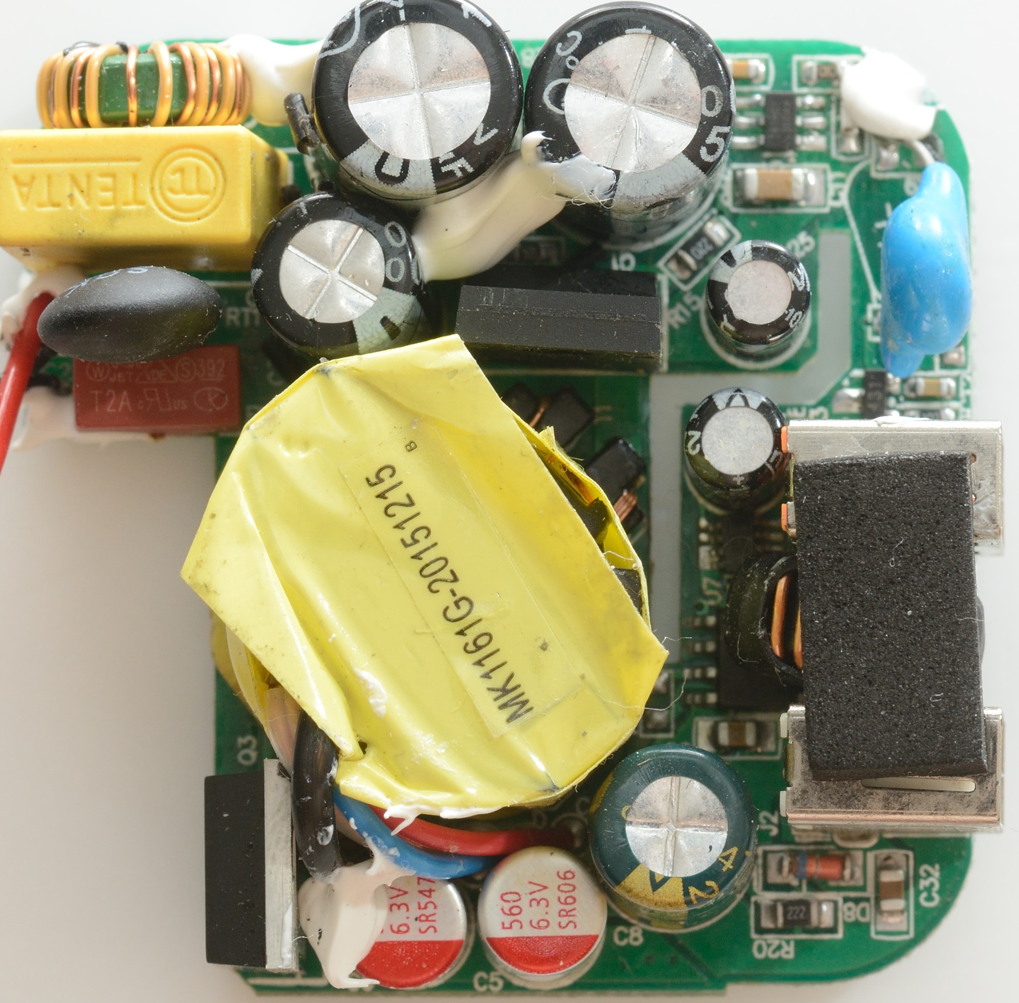
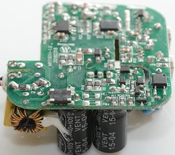
The circuit board has lots of parts on it. Lets start at the mains input (Red/black wires): A red 2A fuse and a black inrush current limiter, then a capacitor and a common mode coil. After the 3 capacitors there is the mains switcher transistor (Q1) and the mains switcher controller (Marked 281H01/360AP). Just beside the slot in the circuit board there is a blue safety capacitor.
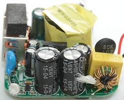
On the other side of the transformer we have the rectifier (Q3), this is a transistor, i.e. the circuit is using synchronous rectifications.
The chip besides the usb connectors marked 431 is probably the voltage reference.
The inductor between the two usb connectors is for the QuickCharge converter.
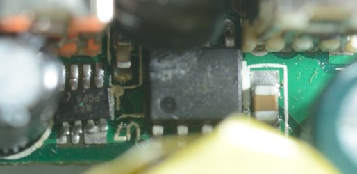
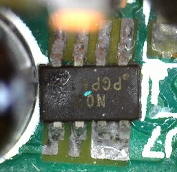
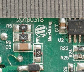
Here I have zoomed in on the chips behind the usb connectors. The large chip is a HX1314G DC-DC converter. That means the small chip must be the QuickCharge controller (It is marked: N03/PGP6 maybe 61). The mounting of the small IC is not very good.
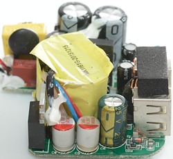
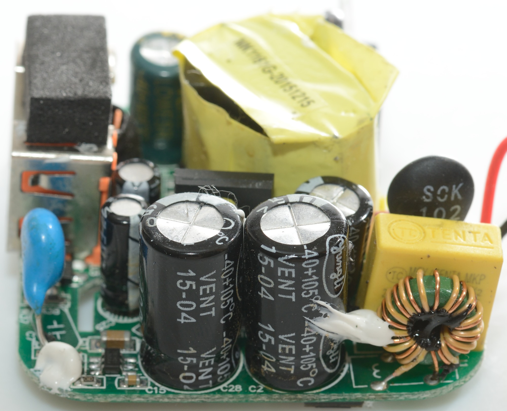
The first photo has the rectifier transistor. Notice one of the capacitors is marked 25V, it must be for QuickCharge.
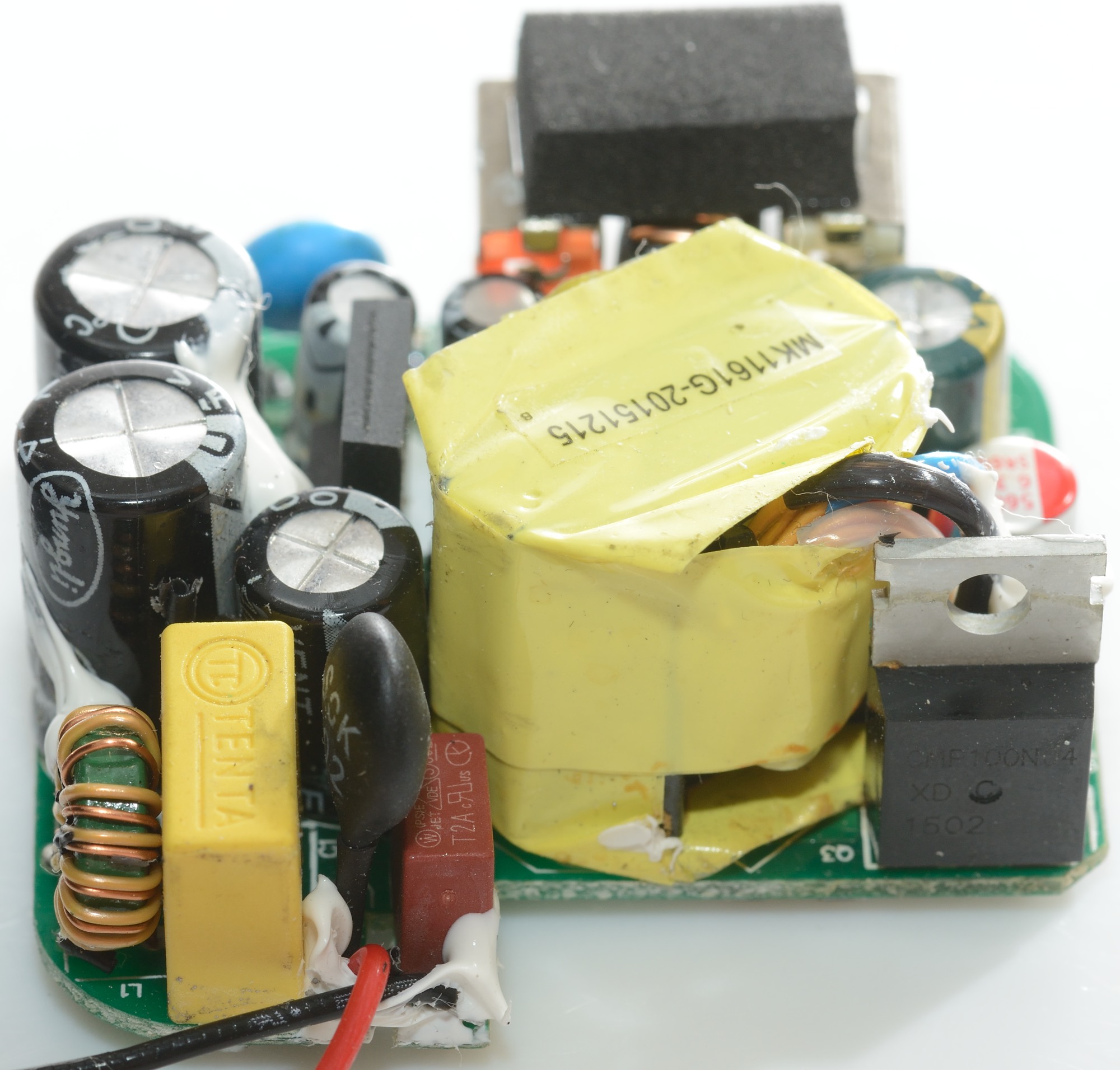
On the second photo the QC inductor and the safety capacitor can be seen. Between the two usb connectors are a small led.

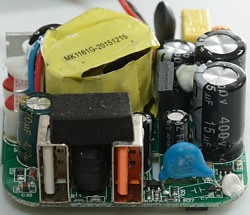
On the first photo the mains switcher controller and the common mode coil can be seen. The second photo start with the common mode could, then the yellow capacitor, the black inrush current limiter, the red fuse and the transformer and the rectifier transistor.
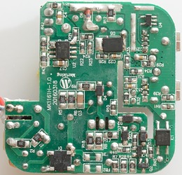
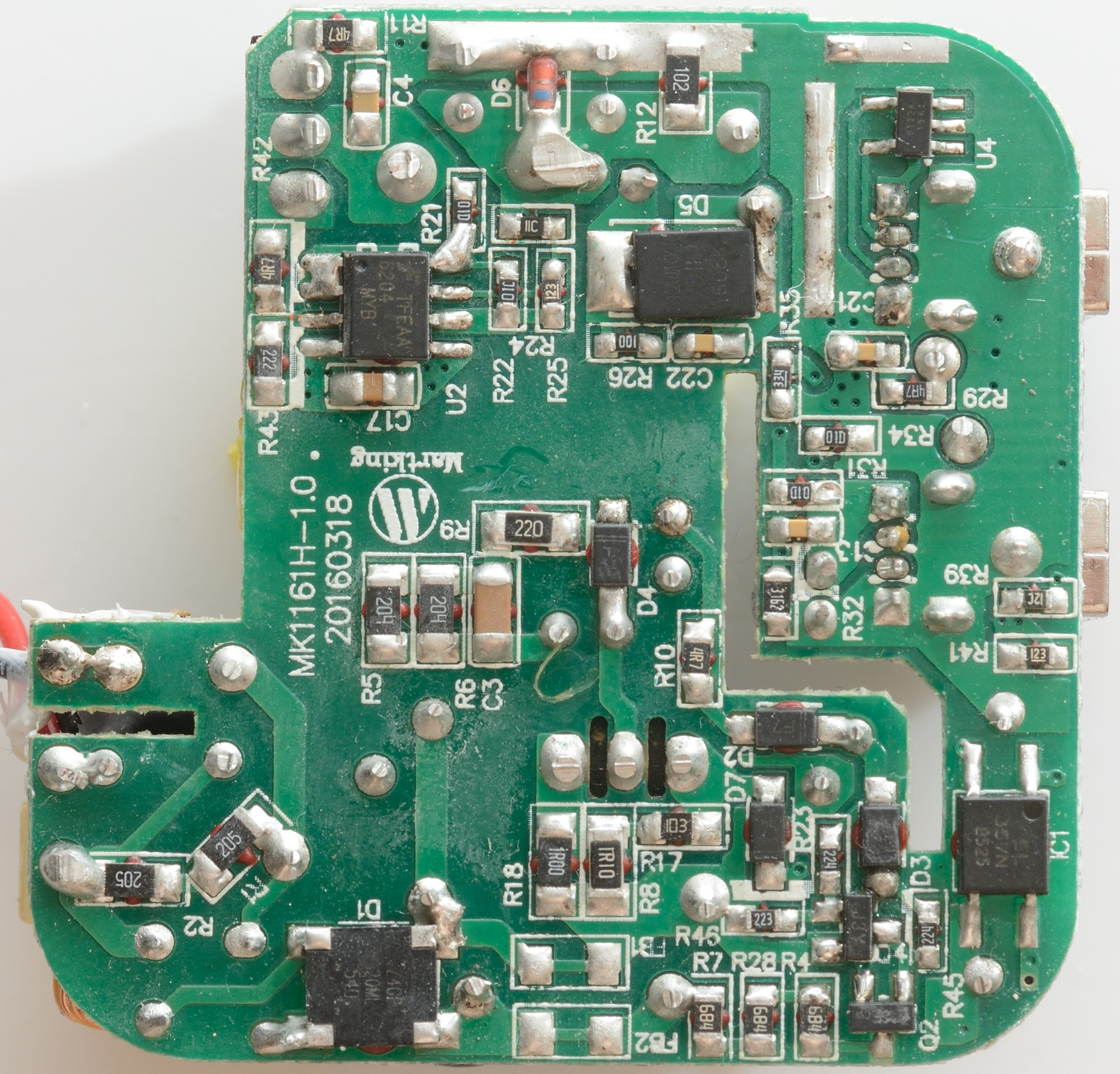
There is also a lot of parts on the bottom too. At the input there is a bridge rectifier (D1). A optocoupler (IC1: EL357N). Auto coding of the 2.4A usb output (U4). Synchronous rectifier controller (U2). The diode D5 is related to QuickCharge.
The question is how do the circuit work, the QC output can either increase or decrease voltage and it need a output voltage range from 3.6V to 12V, i.e. both below and above 5V. Looking at the transformer it can be seen that it has two secondary windings, one for 5V and one for QC (It is 14.8V unloaded). D5 is rectifier for QC and the 25V capacitor is used to smooth that voltage.
The isolation distance is enough. Due to the plastic shield going through the slot, it does not matter how close parts are to the slot (Without the shield the distance would have to be 4mm).
Testing with 2500 volt and 5000 volt between mains and low volt side, did not show any safety problems.
Conclusion
This charger is very powerful, also too powerful for a single usb output. I would very much have liked an overcurrent protection on the 2.4A output. Except for that the charger work very well with low noise and auto coding on both outputs.
I will call it a good usb charger for both regular and quick charge usage.
Notes
The usb charger was supplied by Banggood for a review.
Read more about how I test USB power supplies/charger