BlitzWolf dual port usb charger BW-S2
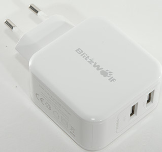
Official specifications:
- Model: BW-S2(EU)
- Input: AC 100-240v 50/60Hz
- Output: DC 5V/4.8A(2.4A per port)
- Size: 54 X 54X 28.5mm /2.1 X 2.1 X 1.1 inch
- Color: White
I got it from Banggood
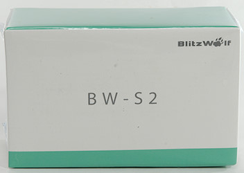
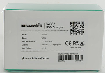
Blitzwolf is using a new box for their chargers with some information on it.
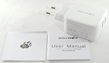
The box contained the charger, a instruction sheet and a note.
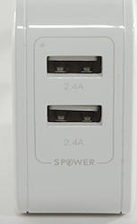
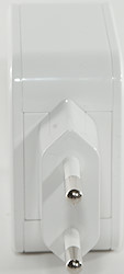
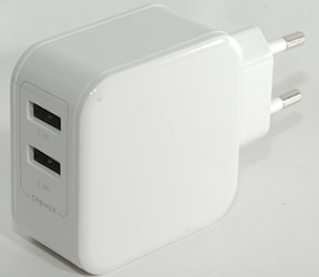
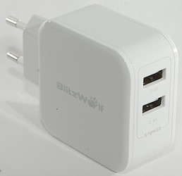
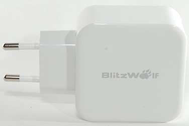
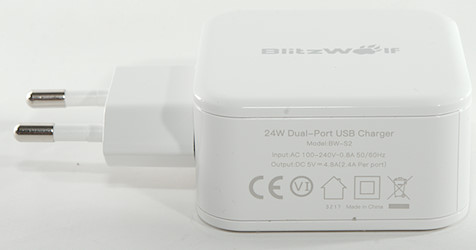
Measurements
- Power consumption when idle is 0.07 watt
- The 2 usb outputs share ground connection, the overload chip is in the + line.
- The 2 usb outputs are auto coding with Apple 2.4A as maximum.
- There is a blue led inside the box between the usb connectors.
- Weight: 89.9g
- Size: 92 x 54.1 x 28.5 mm
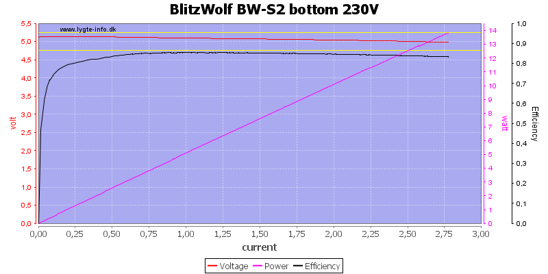
The output can deliver 2.8A before overload protection trips, this is fine for one port. Efficiency is also fairly good.
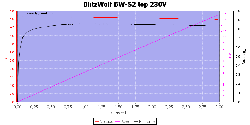
The other port has a slightly higher overload protection, but it is still good.
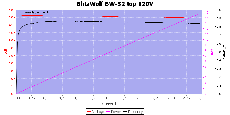
Using 120VAC do not change anything, except the efficiency gets slightly better at low loads.
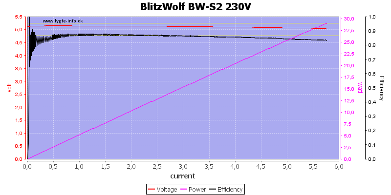
Using both ports in parallel works fine and I can draw about 5.6A total, this is good.
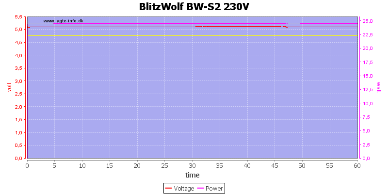
A one hour test with 4.8A load was no problem.
The temperature photos below are taken between 30 minutes and 60 minutes into the one hour test.
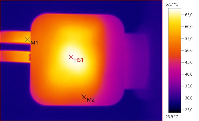
M1: 59,6°C, M2: 49,4°C, HS1: 67,7°C
HS1 is the transformer
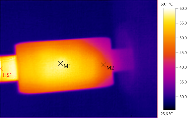
M1: 58,4°C, M2: 45,9°C, HS1: 60,1°C
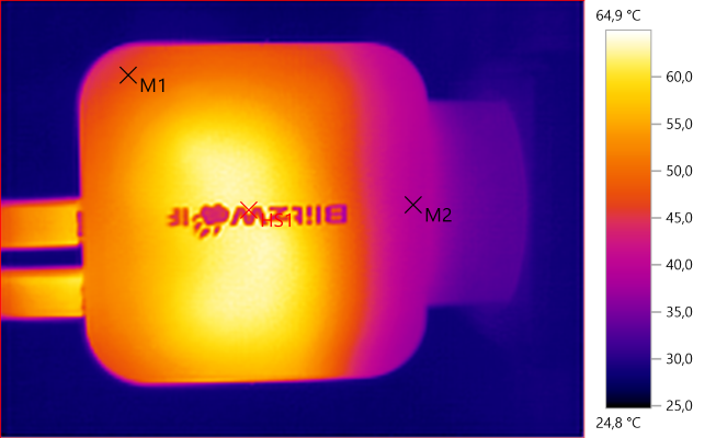
M1: 47,0°C, M2: 39,0°C, HS1: 64,9°C
Again HS1 is the transformer.
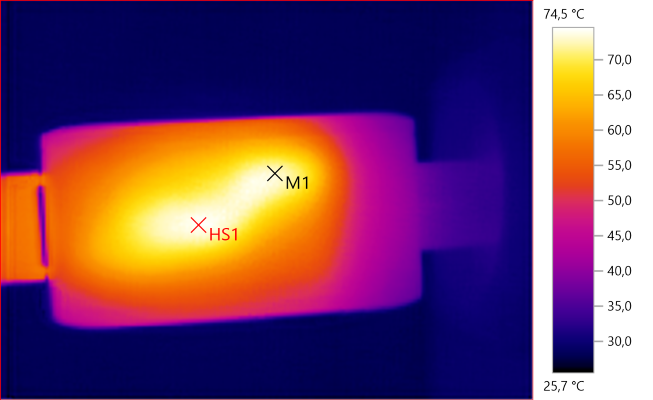
M1: 72,9°C, HS1: 74,5°C
M1 and HS1 is due to the white stuff transferring heat from the rectifier heatsink.
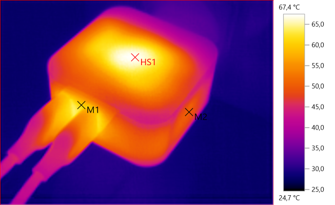
M1: 60,9°C, M2: 50,3°C, HS1: 67,4°C

At 0.5A the noise is 3mV rms and 120mVpp.

At 1A the noise is 5mV rms and 104mVpp.

At 2.5A the noise is 7mV rms and 88mVpp.
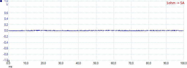
At 5A the noise is 6mV rms and 47mVpp, the noise is very low.
Tear down
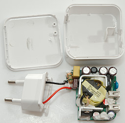
Applying some pressure on the sides with a vice popped the lid off and I could pull the electronic out.
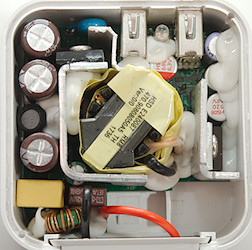
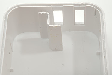
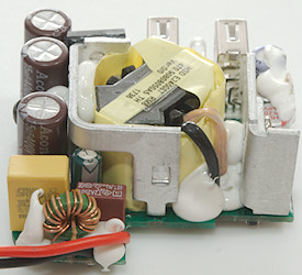
The circuit board in the box, the white stuff secures the part against shocks (from dropping) and may improve heat transfer. Notice the white plastic shield besides the usb connectors, that is a way to improve the isolation to mains.
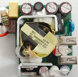
At the mains input is a common mode coil and a fuse, there is also a inductor between the mains smoothing capacitors. The mains switcher transistor is mounted on a heatsink that goes around the transformer, there is a safety capacitor next to the transistor.
On the low volt side the transformer has flying leads, the rectifier is mounted on a small heatsink. A led can be seen between the two usb connectors.
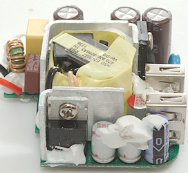
The rectifier transistor and 3 low volt smoothing capacitors.
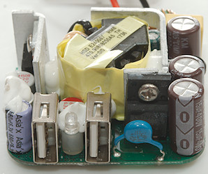
The leds between the usb connectors. The safety capacitor has a lot of safety approvals (They always have that) and behind the capacitor is the mains switcher transistor.
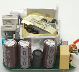
3 mains smoothing capacitors with a inductor between.
The common mode coil with the fuse behind it. The flying leads from the transformer are also easy to see here.
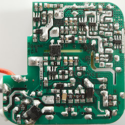
All the chips are on this side of the circuit board. Lets start with the bridge rectifier (BD1) close to the mains input. On the mains side is also the switcher controller (U1) close to the opto-coupler (U2) that is mounted across a slot in the circuit board.
On the low volt side is the synchronous rectifier controller (U5) next to the rectifier transistors legs. The two current limiting chips (U3 & U4) has very heavy tracks from the capacitors to the usb connectors. This also shows that each usb connector has a its own capacitor after the current limiting switch. Between the usb connectors is the auto coding ship (U6).
This means I am missing one IC, the reference. It may be part of another IC, but the most likely reason is that Q2 is mislabeled and is a reference IC.
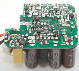
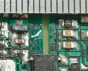
The safety distance is good due to the slot.
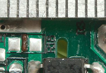
But the slot stops before the tracks and this means "only" 5mm, this is not perfect.
Testing with 2830 volt and 4242 volt between mains and low volt side, did not show any safety problems.
Conclusion
The usb charger can deliver the rated power with stable output voltage, has individual port protection and very low noise. Safety is fairly good.
Notes
The usb charger was supplied by Banggood for a review.
Read more about how I test USB power supplies/charger


