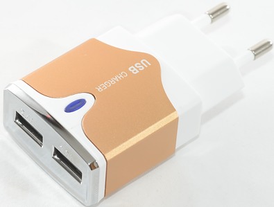
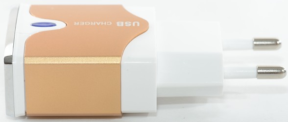
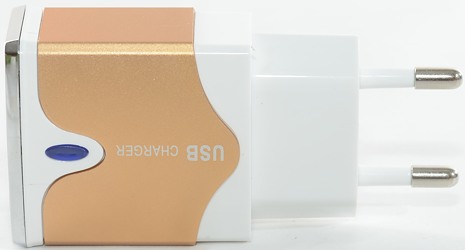
Dual USB EU AC Power Adapter
Official specifications:
- Input: 100-240V AC, 50/60Hz
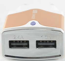
- Output: 5V DC 2.4A, 1A
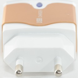
- EU Plug AC
- Protective circuit to prevent overcharging (IC chip).
- Offers fast, efficient charging
- Current limited, with reverse circuit protection. Will not overcharge your device.
- Device can be used immediately, while charging.
- Size: approx.7.9*3.8*2cm
- Compatible with Samsung S5 S6 iPhone HTC and other Smart phones requiring powerful current
I got it from Ebay dealer: funfushion
Measurements
- Power consumption when idle is 0.14 watt
- 2.4A usb output is coded as Apple 2.1A (Oops)
- 1A usb output is coded as Samsung
- All outputs are in parallel.
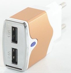
- There is a led hidden between the usb connectors.
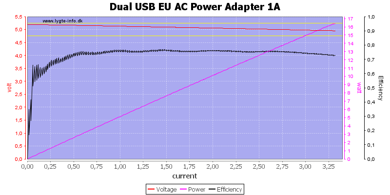
The 1A output can deliver way more than 1A.
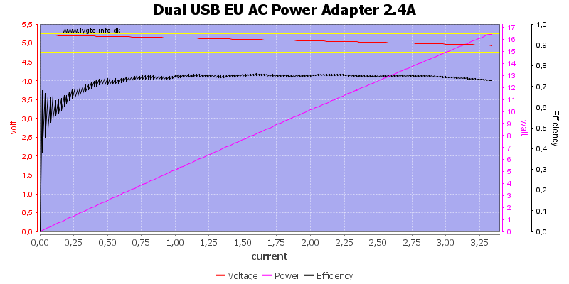
The 2.4A output can deliver same current as 1A output.
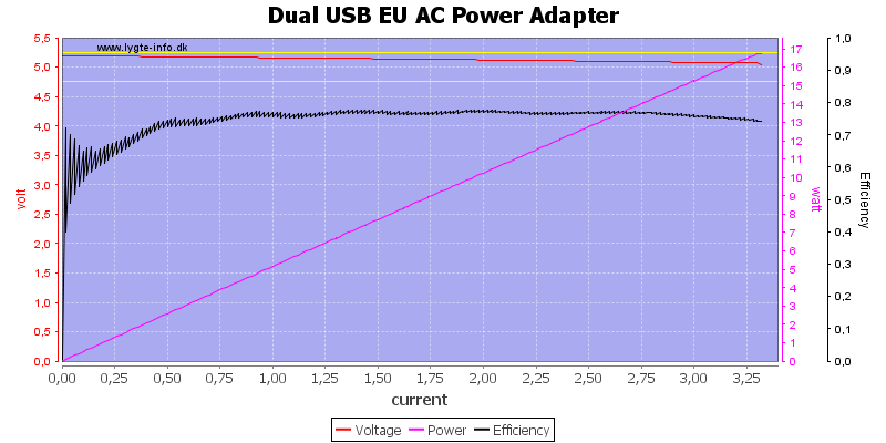
This is because they are in parallel.
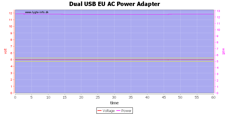
The charger could deliver 2.5A for one hour, but it was to hot to hold after the test.
The temperature photos below are taken between 30 minutes and 60 minutes into the one hour test.
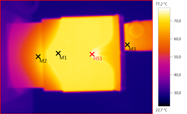
M1: 72,2°C, M2: 67,0°C, M3: 66,4°C, HS1: 77,2°C
With the aluminium wraparound the temperature around the charger is mostly equalized, making it difficult to see what parts gets hot.
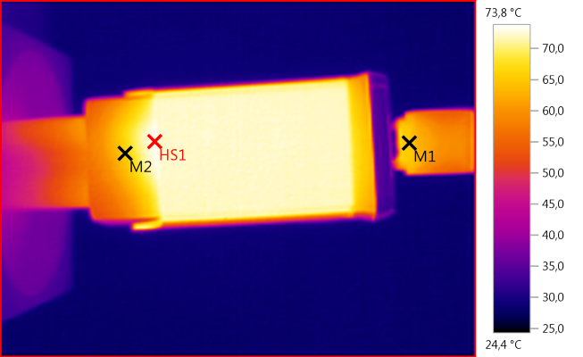
M1: 65,0°C, M2: 65,7°C, HS1: 73,8°C
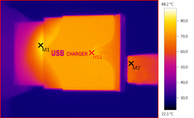
M1: 80,2°C, M2: 64,8°C, HS1: 88,2°C
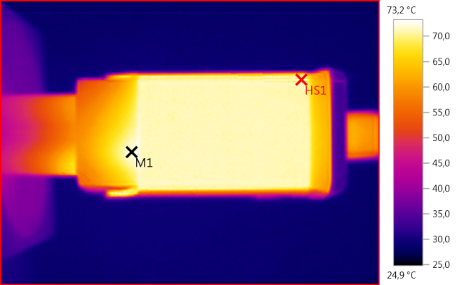
M1: 72,3°C, HS1: 73,2°C

M1: 64,1°C, HS1: 103,1°C
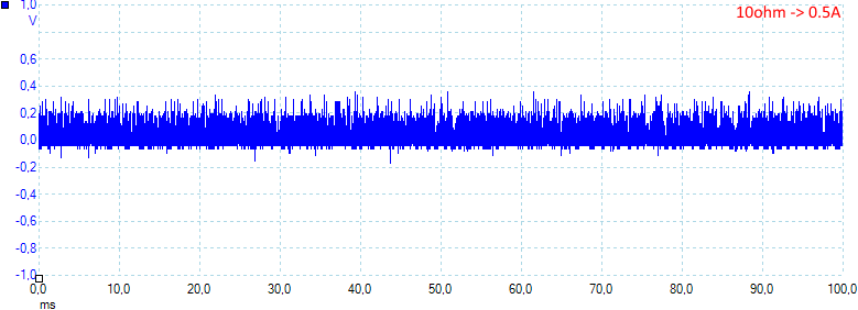
Noise at 0.5A load is 83mV rms and 555mVpp
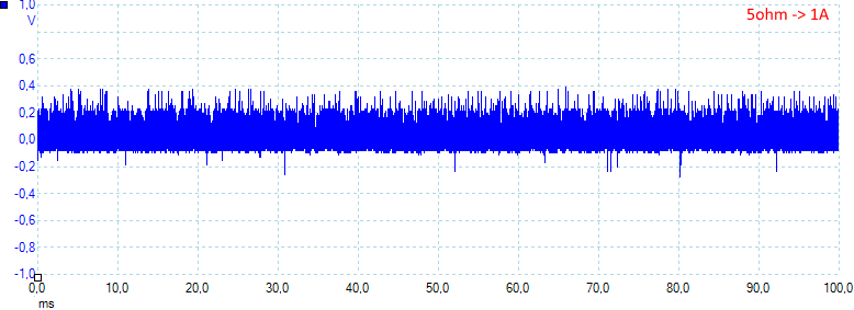
Noise at 1A load is 126mV rms and 723mVpp
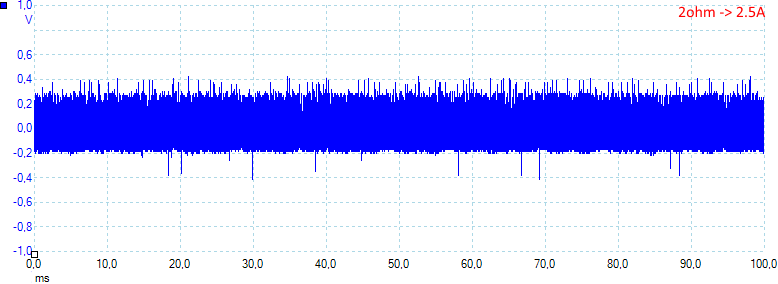
Noise at 2.5A load is 160mV rms and 860mVpp
Tear down
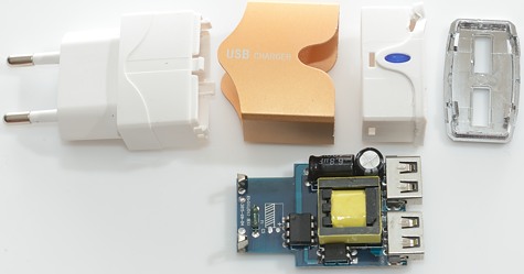
The adapter was clicked together and I could break it open with a screwdriver.
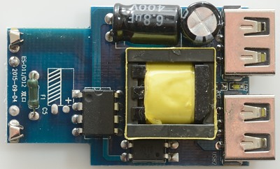
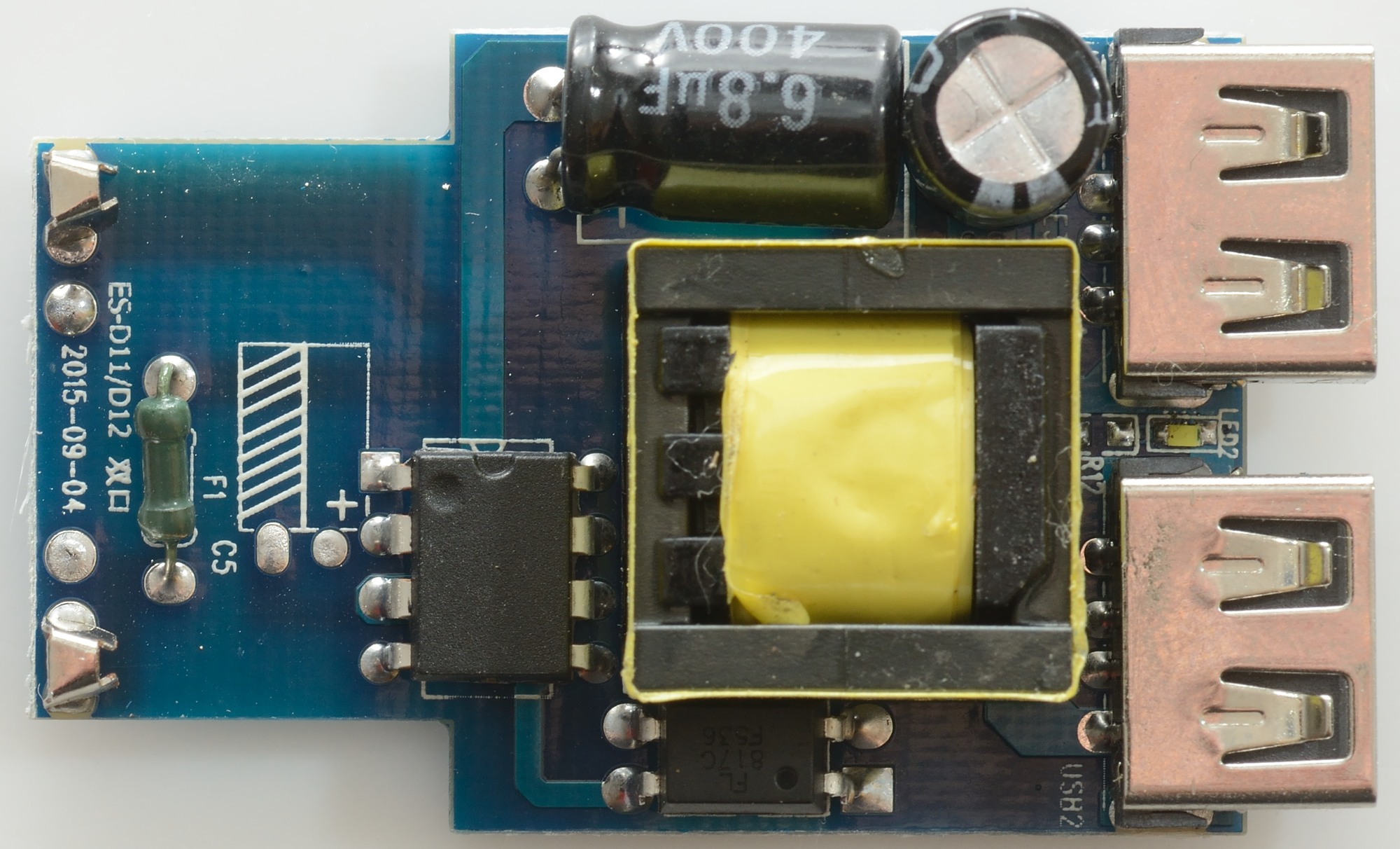
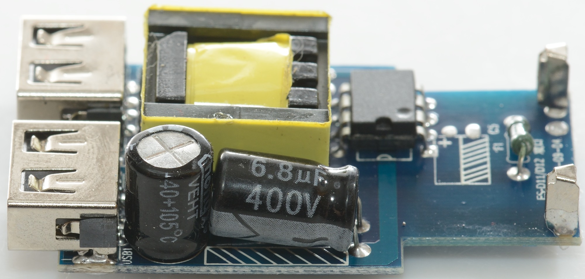
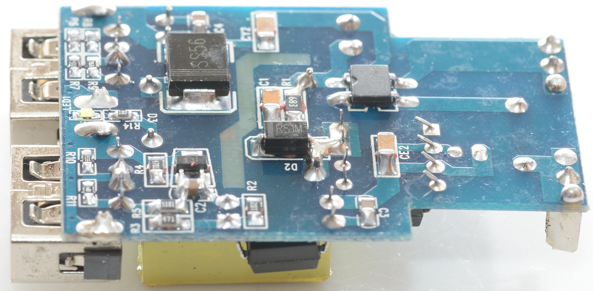
At first glance it might look nice, but it is not: The two electrolytic capacitors are way to close for safety.
There is an input fuse (F1). The mains switcher is an unmarked IC. Besides the transformer is a opto coupler.
Between the usb connectors is a led.
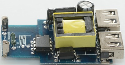
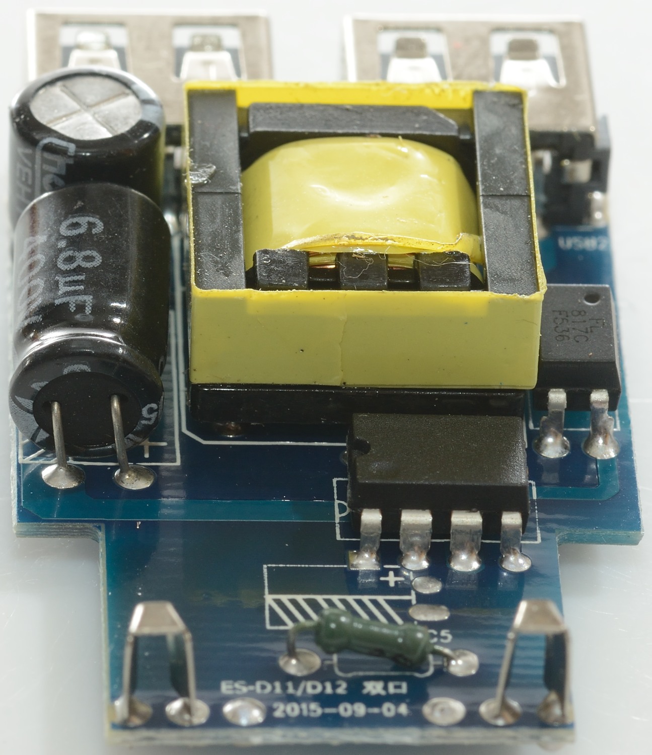
The opto coupler is visible from this side.

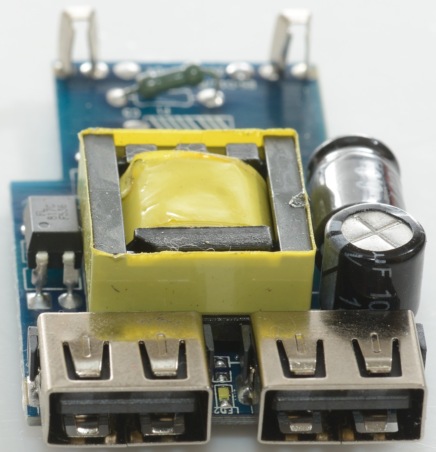
The fuse and the led (LED2) between the usb connectors is visible from here.
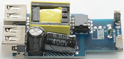
The two capacitors. The top of the 400V capacitors will have mains voltage, but the plastic around the other capacitors is not rated for mains voltage isolation. To make this safe there must be plast, paper or yellow tape between the capacitors.
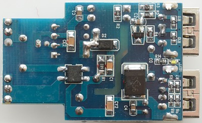
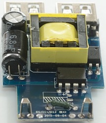
On this side we have the bridge rectifier and the rectifier diode (SS56) and the voltage reference (3 pin chip). There is also a led more (LED1).
The usb coding resistors can be seen under the usb connectors.

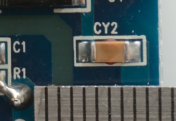
The isolation distance is below 2mm it is supposed to be above 6mm. The CY2 part is supposed to be a safety capacitor, but is just an ordinary one.
The charger failed both 2500 volt and 5000 volt test, this makes the charger dangerous everywhere.
Conclusion
This charger has very bad safety, stay away. It also is bit noisy and gets very hot when fully loaded.
Notes
Index of all tested USB power supplies/chargers
Read more about how I test USB power supplies/charger
How does a usb charger work?