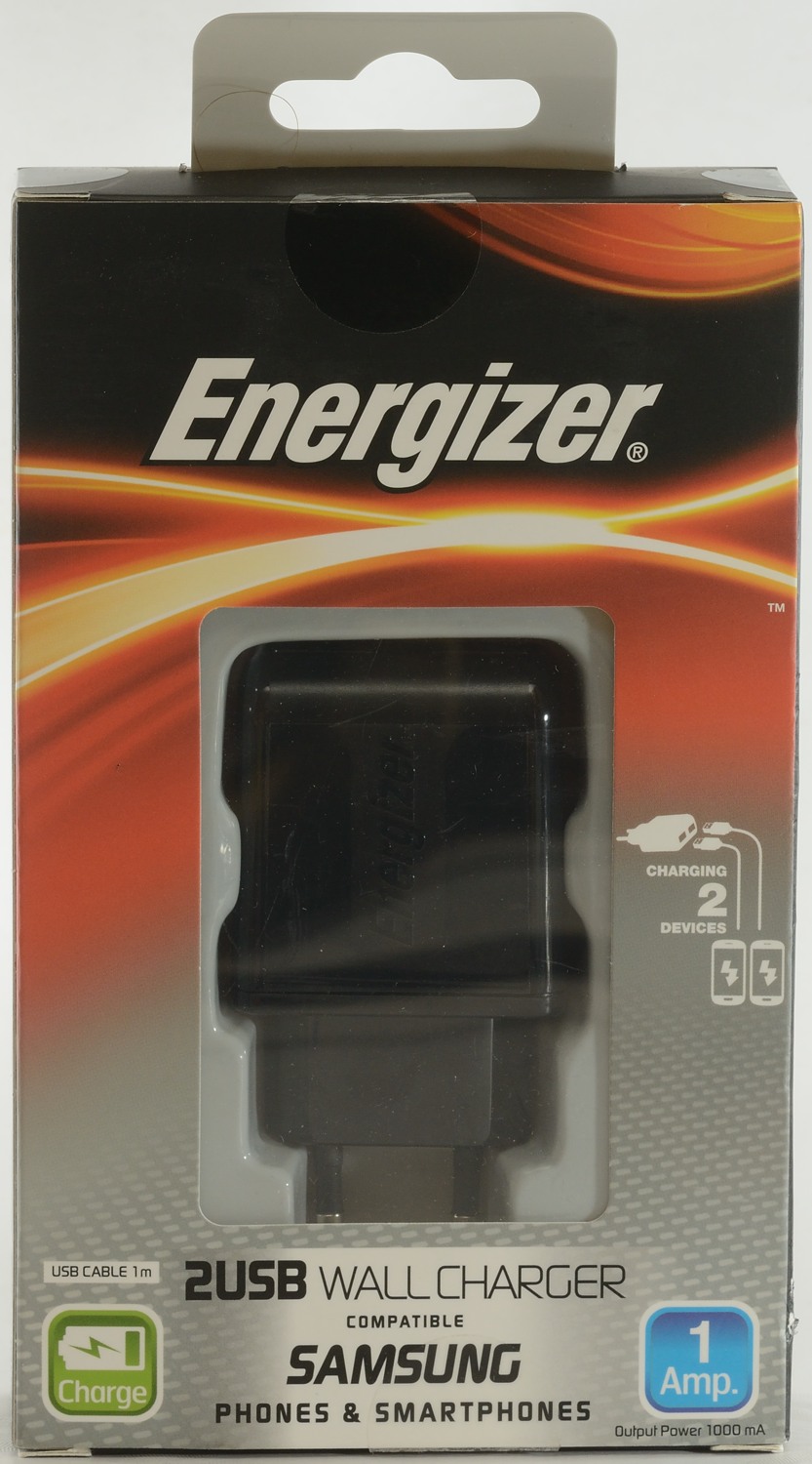
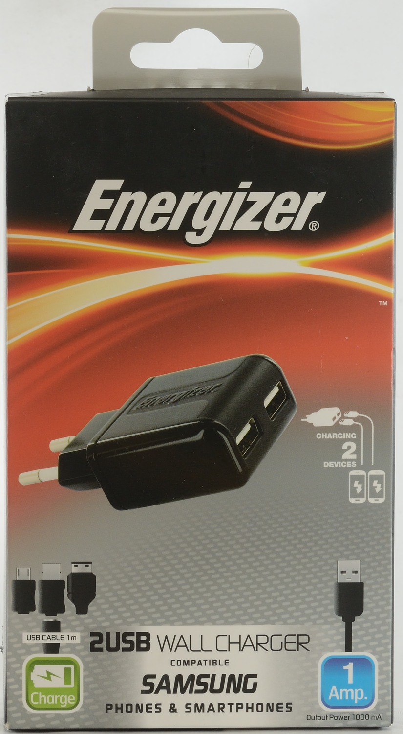
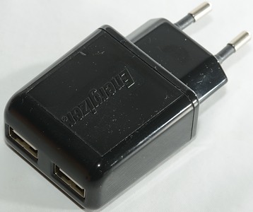
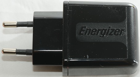
Energizer 2 usb Wall Charger AC2UEU
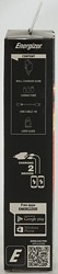
Official specifications:
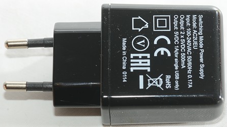
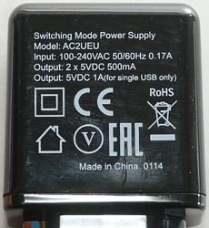
- Input Power: AC 100-240V (50-60Hz)
- Output Power: DC 5V-1A
- 2 USB Ports
- Cable Length: 1m
- Compatible with Micro USB devices
- CE (EMC, LVD), RoHS, Reach, ErP2, FCC


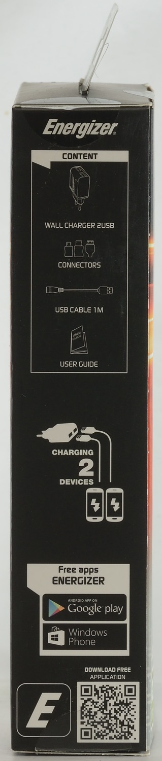
I got it in a cardboard box, it is supposed to contain an instruction sheet, the charger and one usb cable.
Measurements
- Power consumption when idle is 0.08 watt
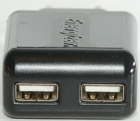
- Both usb outputs are coded as Apple 1A
- The two outputs are in parallel.
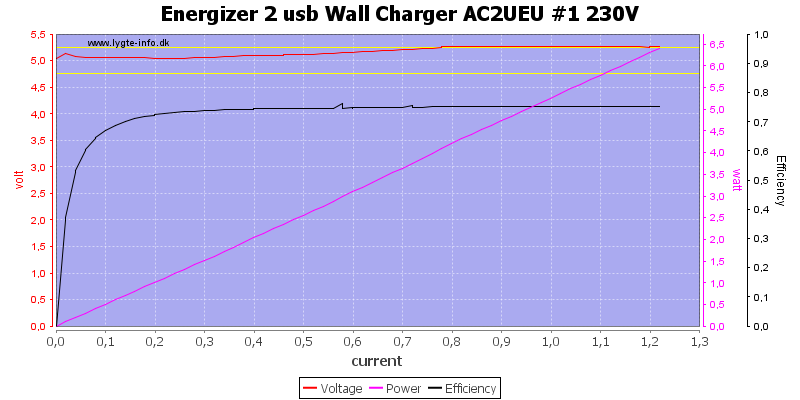
It can deliver 1.2A, this is a fine value for a 1A charger.
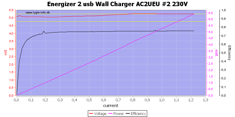
The other output delivers the same.
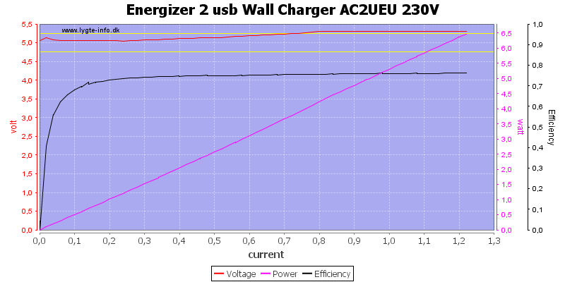
With both used together the output is still the same, they are in parallel and the charger can only deliver 1.2A total.
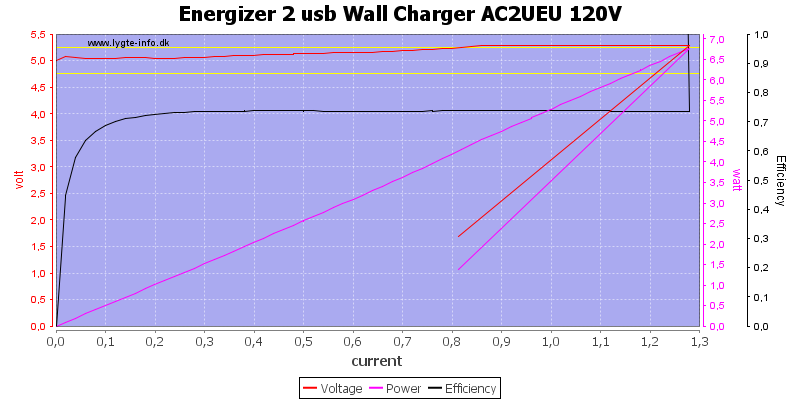
At 120VAC it can deliver slightly more.
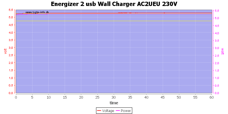
No problems running one hour at 1A.
The temperature photos below are taken between 30 minutes and 60 minutes into the one hour test.
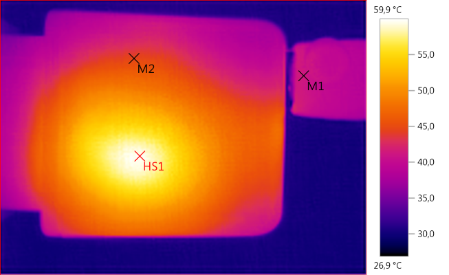
M1: 41,3°C, M2: 44,5°C, HS1: 59,9°C
HS1 looks to be the transformer. It do not look like the rectifier diode is visible.
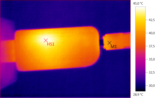
M1: 40,0°C, HS1: 45,0°C
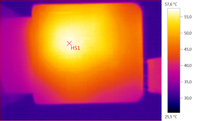
HS1: 57,6°C
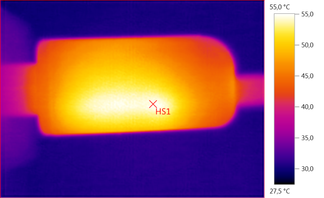
HS1: 55,0°C
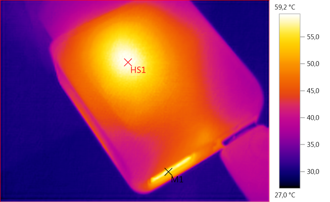
M1: 56,7°C, HS1: 59,2°C
The reason for the warm usb connector may be the rectifier diode.
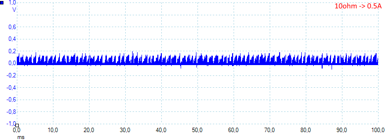
At 0.5A the noise is 46mV rms and 353mVpp.
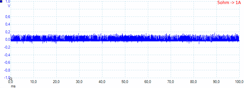
At 1A the noise is 55mV rms and 344mVpp.
Tear down
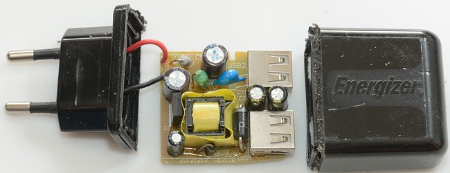
It looked like it just needed a squeze and maybe a whack with my mallet, after a couple of squezes and whacks I decided to cut it open.

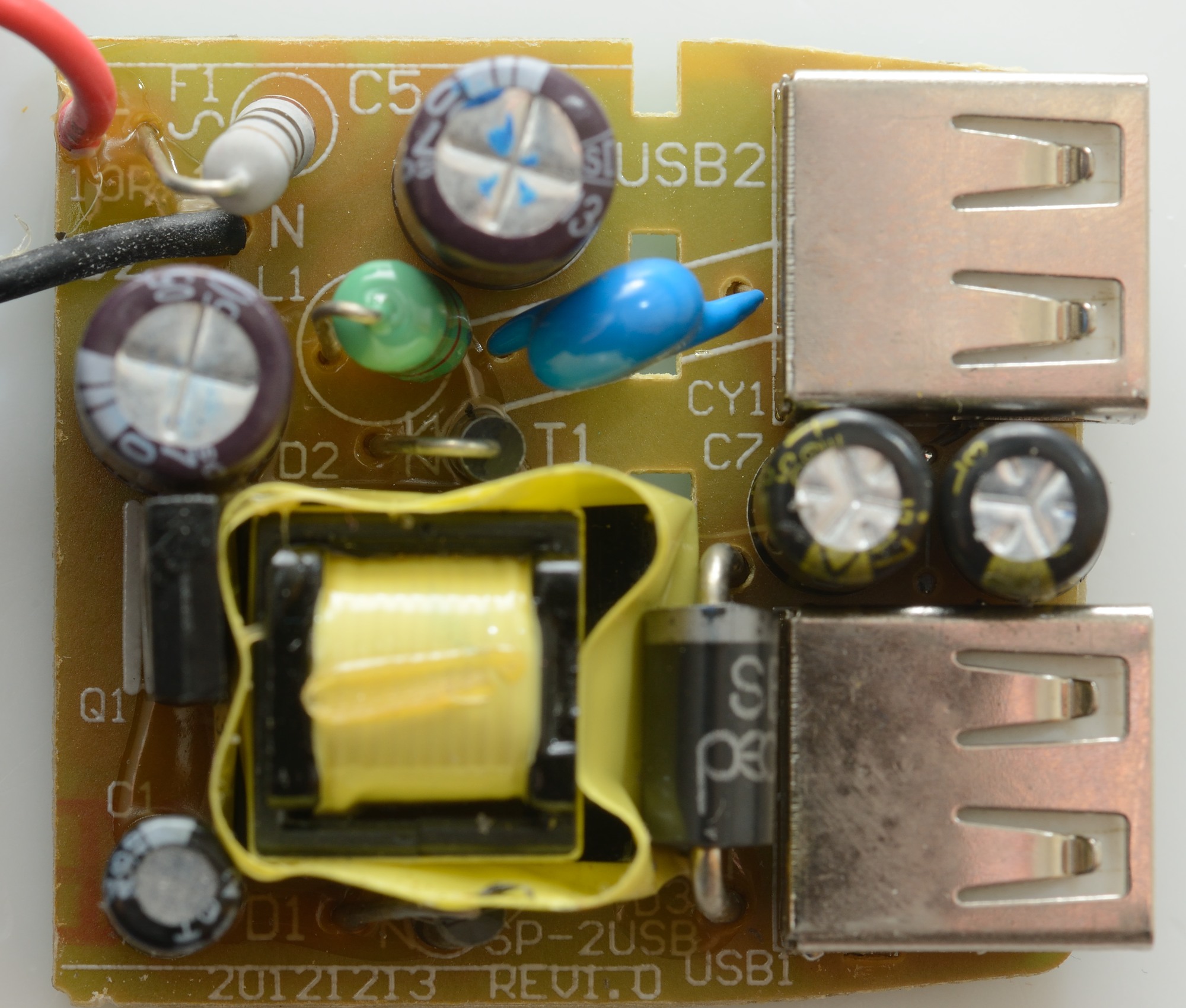
On this side there is a fusible resistor (F1) at the mains input, a inductor (L1) between the two capacitors. There is the usual blue safety capacitor. The rectifier diode is rather large for a 1A supply (good). The mains switcher transistor (Q1) is placed against the transformer.
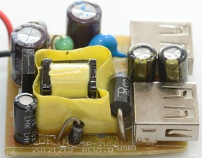
The small diode and capacitor is internal power for the switcher (See linked article at the bottom).

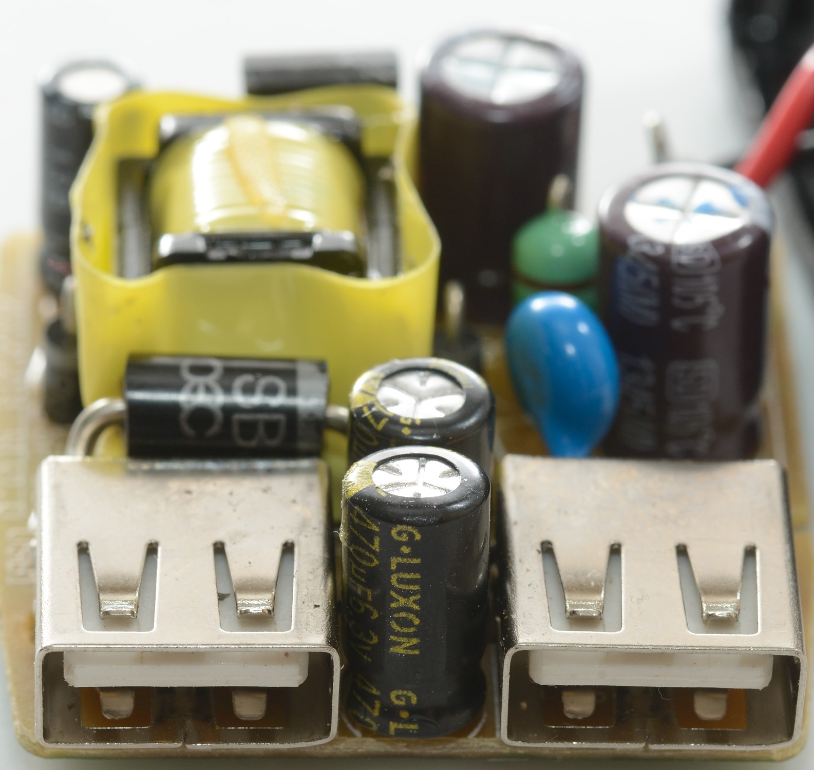
There is two output capacitors between the usb connectors.
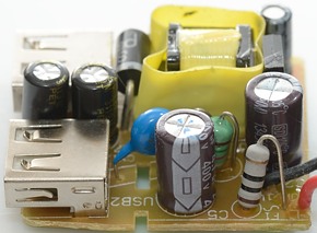
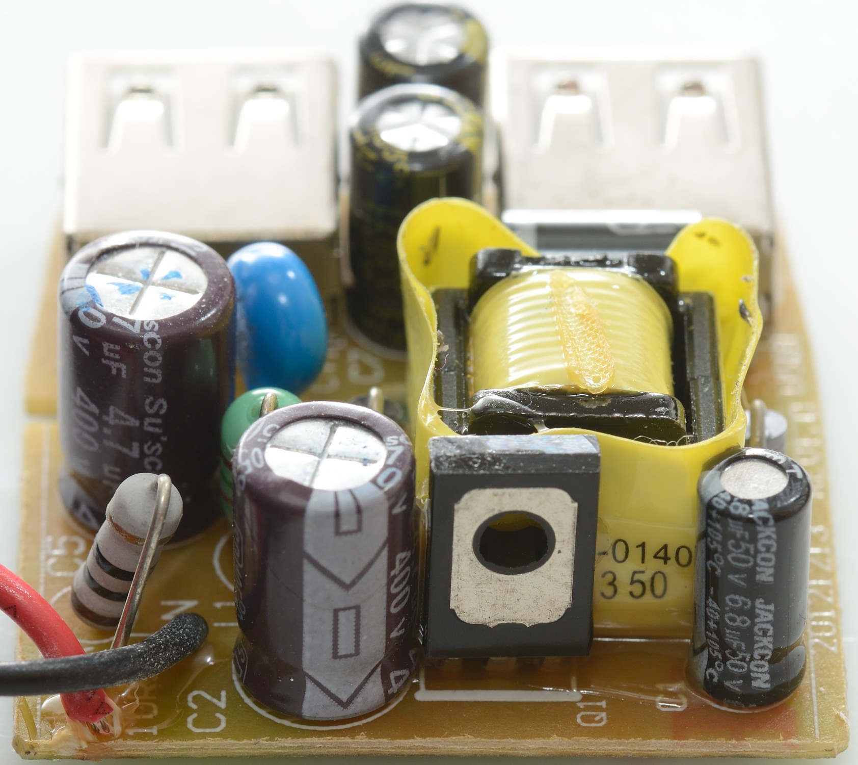
From this side the safety capacitor, the inductor and the fusible resistor can be seen in front of the transformer.

The mains switcher transistor is placed against the transformer.
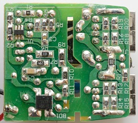
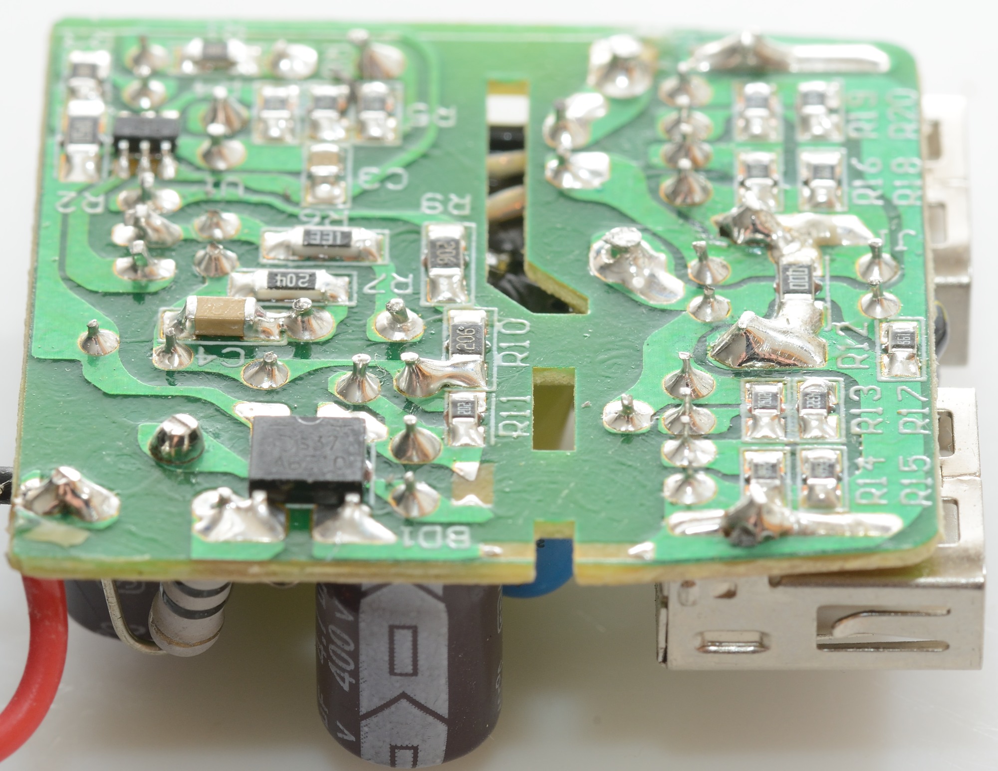
On this side is the mains switcher controller (U1) and a bridge rectifier (BD1).
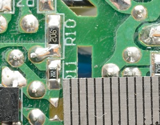
On the low volt side is coding resistors for the usb connectors and a 0 ohm resistor used as a bridge accross the track on the circuit board.
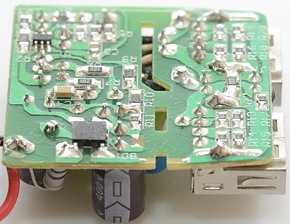
Safety looks good with cut-out in the circuit board and good distance.
Testing with 2830 volt and 4242 volt between mains and low volt side, did not show any safety problems.
Conclusion
Everything looks fine on this charger or would have done a few years ago. Today a DCP coding would be more useful and some more current would also be useful (Especially to justify two usb ports).
Notes
Charger was supplied by Pro backup (probackup.nl)
Index of all tested USB power supplies/chargers
Read more about how I test USB power supplies/charger
How does a usb charger work?