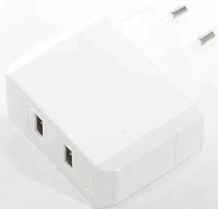
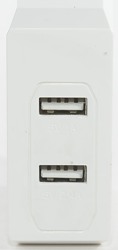
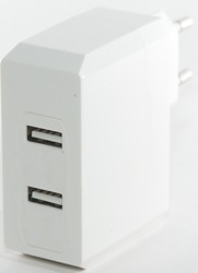
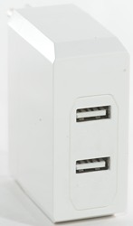
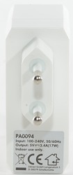
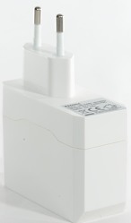
Enerpower Wall adapter EP-L12 2.4A+1A
Official specifications:
- No. of outputs: 2
- Output: 5 VDC 3.4A 17W
- Voltage: AC 100 - 240 V 50/60Hz
- Max output current per port: 2.4A + 1A
Measurements
- Power consumption when idle is 0.22 watt
- 1A usb output is coded as usb charger (DCP)
- 2.4A usb output is auto code with Apple 2.4A as maximum.
- The two output ports are in parallel.
- Weight: 88g
- Size: 87 x 67 x 28.2mm

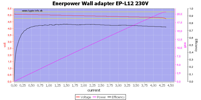
The 1A port can deliver more than 4A before the over load protection kicks in. This do not look like individual port protection.
The 2.4A port has the same limit.
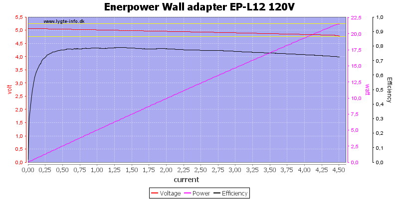
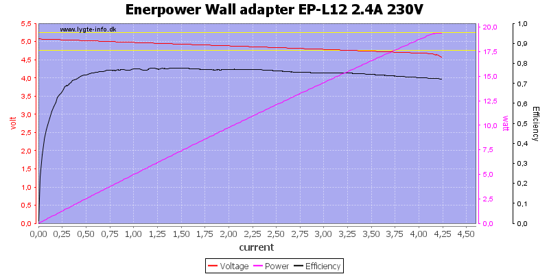
Running both port in paralle also has the same limit (This is not a surprise), here at 120VAC
And here at 230VAC
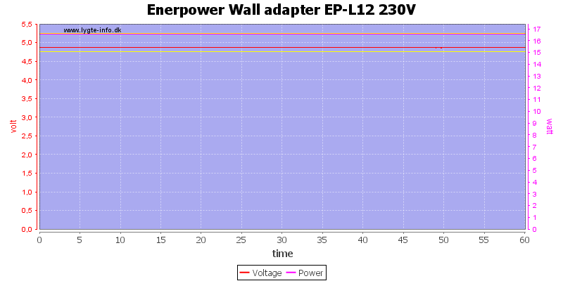
Keeping to rated output power it can easily maintain the output for one hour.
The temperature photos below are taken between 30 minutes and 60 minutes into the one hour test.
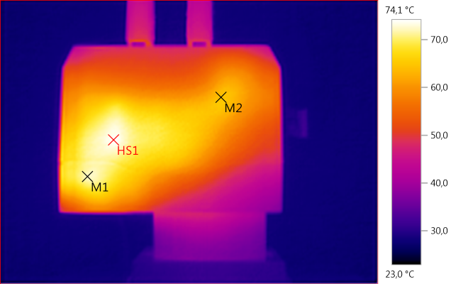
M1: 72,1°C, M2: 64,4°C, HS1: 74,1°C
MS1 is from the transformer and M1 is from the rectifier diode.
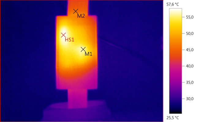
M1: 55,8°C, M2: 45,6°C, HS1: 57,6°C
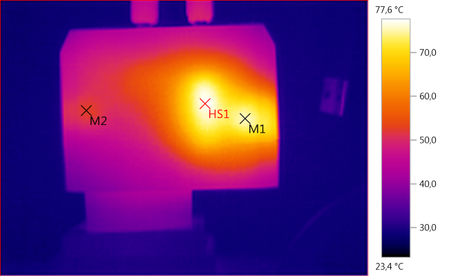
M1: 75,5°C, M2: 52,4°C, HS1: 77,6°C
HS1 is the transformer and M1 is the rectifier diode.
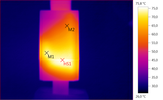
M1: 73,2°C, M2: 58,5°C, HS1: 75,8°C
HS1 is the rectifer heatsink and M1 is the white stuff that is transfering heat from the rectifier heatsink.
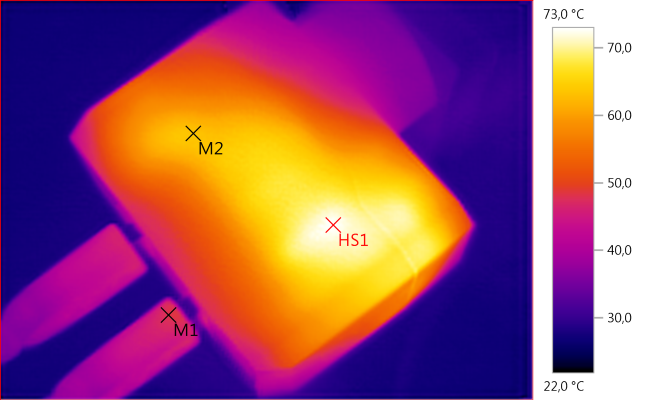
M1: 48,0°C, M2: 63,2°C, HS1: 73,0°C
HS1 is again the transformer.
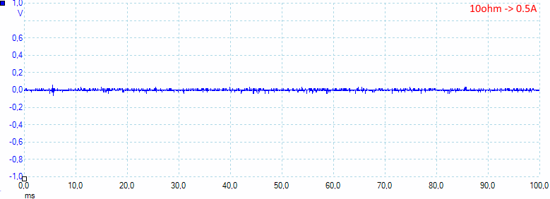
Noise at 0.5A load is: 6mV rms and 113mVpp.
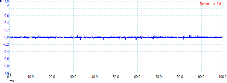
Noise at 1A load is: 18mV rms and 202mVpp.
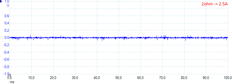
Noise at 2.5A load is: 9mV rms and 181mVpp.
Tear down
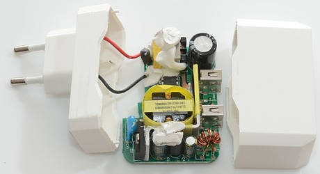
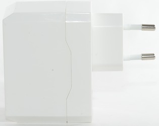
The charger looked easy to open: tie the bottom part in my vice and give the top part a few wacks with my mallet. It worked as expected.
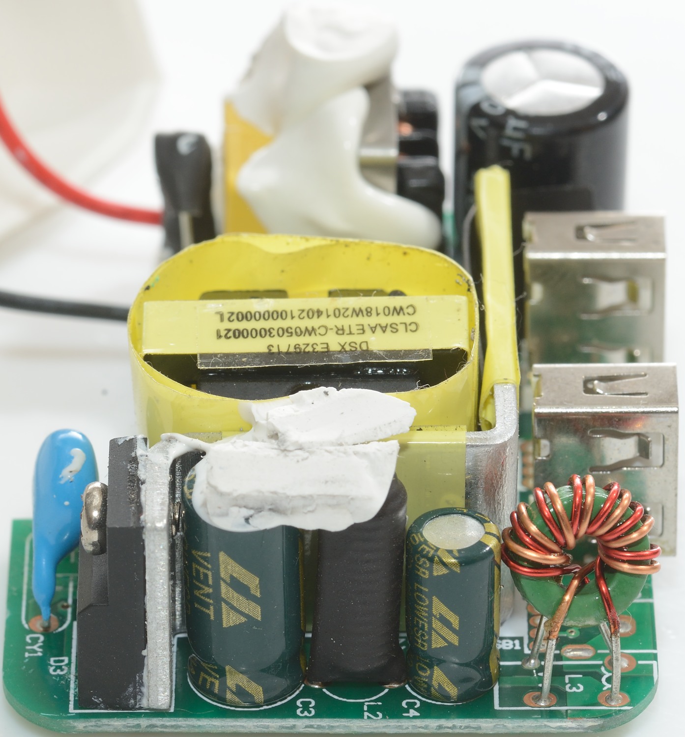
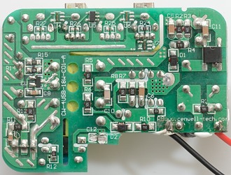
At the mains input is a fuse and a common mode coil. There is no mains switcher transistor, but a single chip that is both the controller and the switcher.
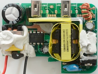
Below the transformer is the opto feedback and the safety capacitor. On the long heatsink the rectifier diode (D3) is mounted. The usb output has a common mode coil.

Here the rectfier diode on the heatsink can be seen, together with a inductor (L2) and a the output common mode coil (L3).
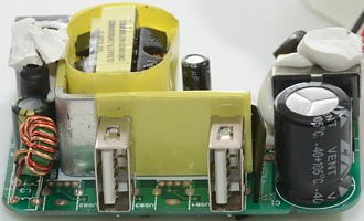
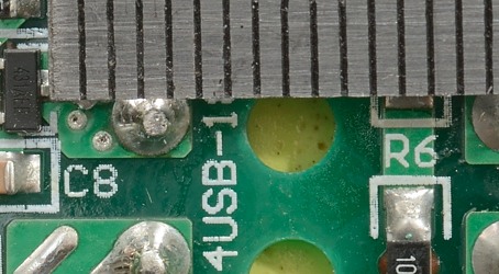
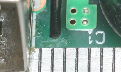
There is space for 4 usb connector, but that would be rather weak charger.
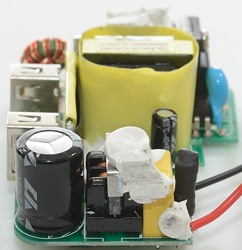
The fuse covered in heatshrink and the input common mode coil is here.
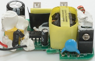
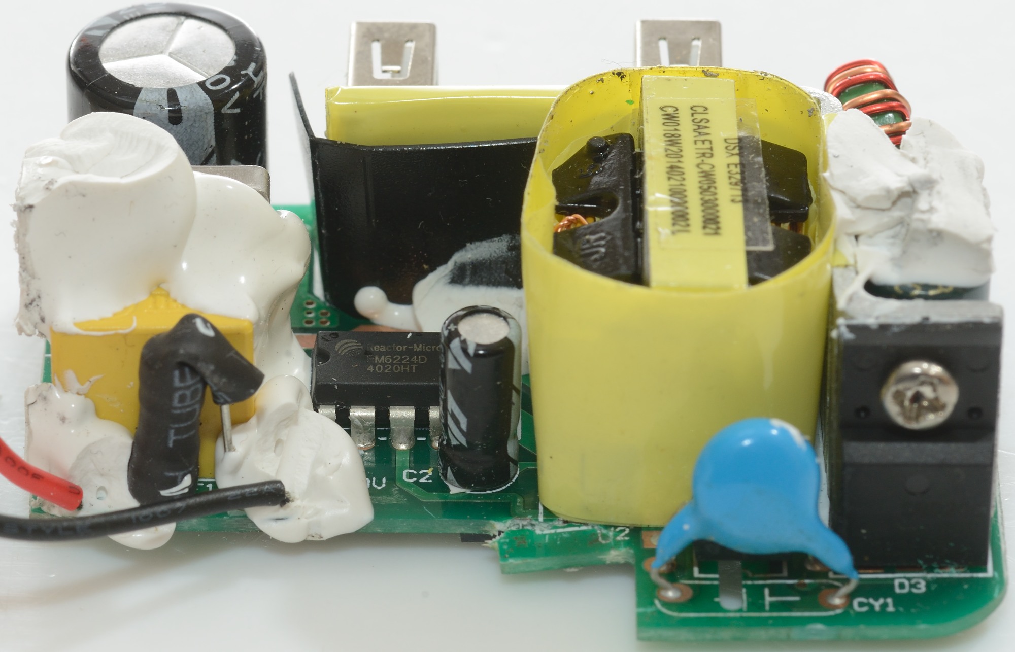
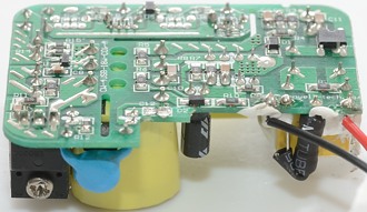
On this image the switcher is easy to see, it is a RM6224D and is rated for 18W (That is 3.6A at 5V) and works at 65kHz.
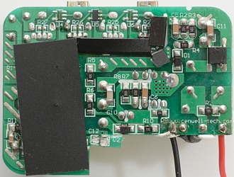
There is some black isolation plastic over the circuit board and into the slot, this is used to improve isolation distances.
On the mains side is a bridge rectifier and on the low volt side is the usb coding chip (U5) and the voltage reference. There is space for 3 more coding chips (U4, U6 & U7). The first two are not needed and instead of the last one a resistor is used (R24) for fixed DCP coding.
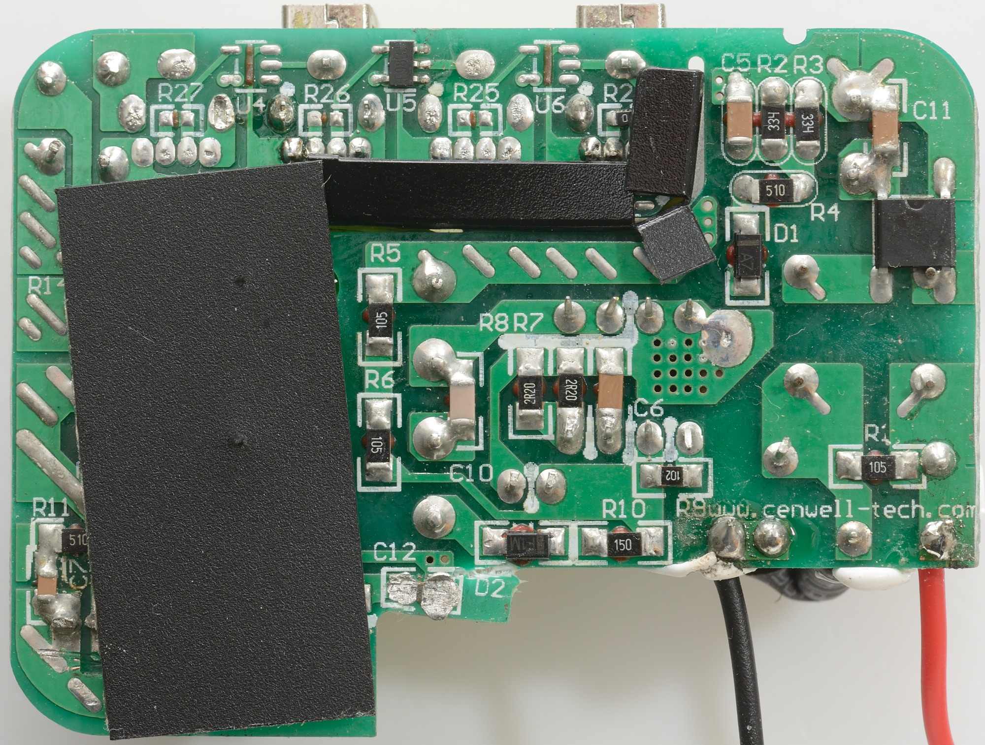
Between mains a low volt side there must be about 6.4mm, it looks fine here.
With air isolation (i.e. a slot) the distance only need to be 4mm, again it looks fine.
I am a bit in doubt about this here, it is probably good enough (i.e. 4mm) with the black plastic installed.
Testing with 2830 volt and 4242 volt between mains and low volt side, did not show any safety problems.
Conclusion
The charger can supply the rated current without problems, has auto coding on one output, low noise and is safe. I would have prefered two 2.4A outputs.
It is a good usb charger.
Notes
Charger was supplied by Enerpower for review.
Index of all tested USB power supplies/chargers
Read more about how I test USB power supplies/charger
How does a usb charger work?