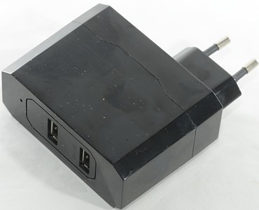
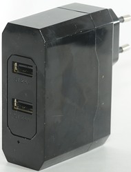
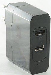
Enerpower Wall adapter EP-L13 2x2.4A
Official specifications:
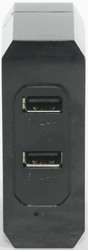
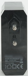
- No. of outputs: 2
- Output voltage: 5 VDC
- Voltage: AC 100 - 240 V
- Max. total output current: 4.5 A
- Max output current per port: 2x 2.4A
Measurements
- Power consumption when idle is 0.08 watt
- Both usb output is auto coding with Apple 2.4A as maximum.
- The two output ports are in parallel.
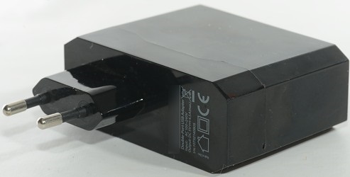
- Weight: 111g
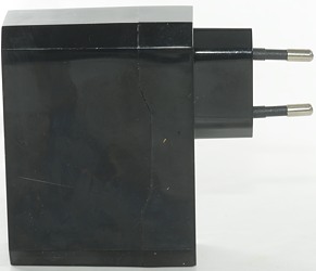
- Size: 95 x 78 x 30.5mm
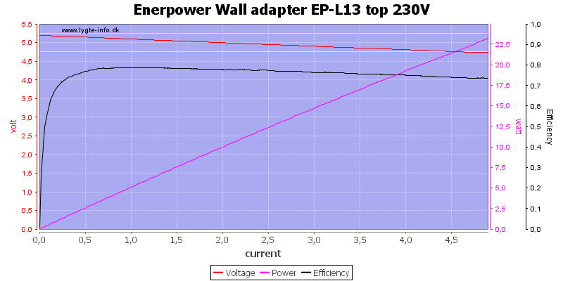
There is no individual overload protection on the outputs, this port can deliver more than 5A
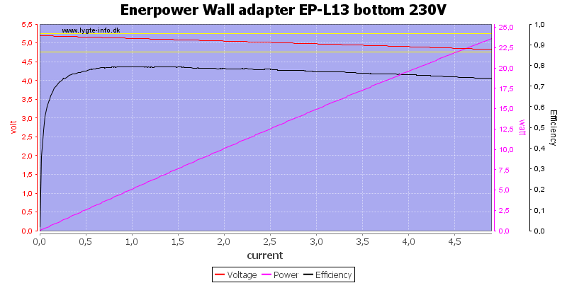
And the other one can do the same.

Together they can deliver more than 6A, even at 120VAC
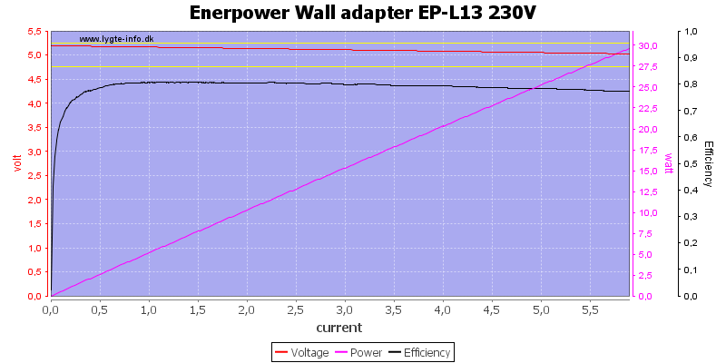
And, of course, also at 230VAC
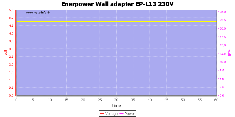
Running one hour at rated load or a bit above is no problem.
The temperature photos below are taken between 30 minutes and 60 minutes into the one hour test.
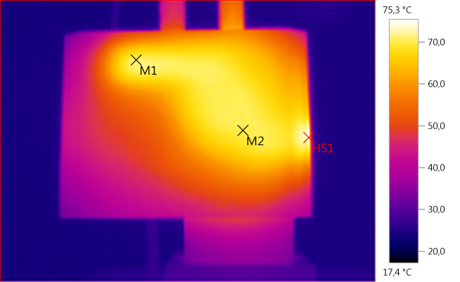
M1: 70,6°C, M2: 70,1°C, HS1: 75,3°C
HS1 is the rectifier diode, M2 is the transformer and M1 is the heatsink for the rectifier diode.
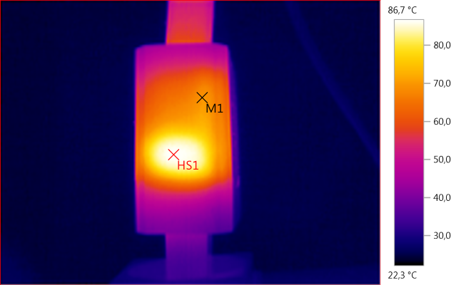
M1: 69,6°C, HS1: 86,7°C
Again HS1 is the rectifier diode (white blob) and M1 is the heatsink for it.
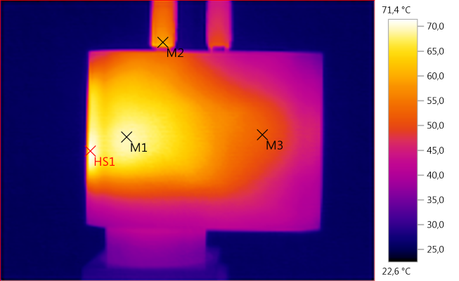
M1: 69,3°C, M2: 59,3°C, M3: 52,1°C, HS1: 71,4°C
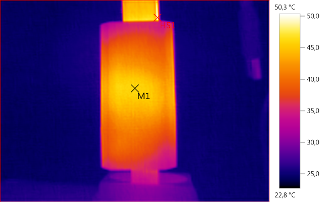
M1: 46,0°C, HS1: 50,3°C
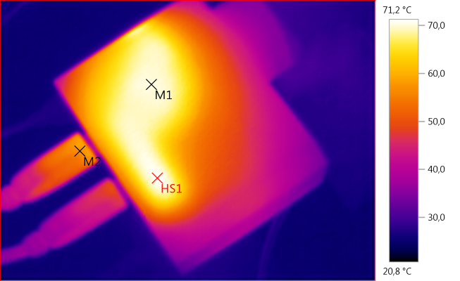
M1: 70,2°C, M2: 56,9°C, HS1: 71,2°C
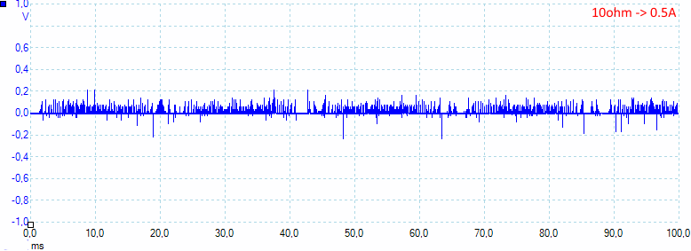
Noise at 0.5A load is: 26mV rms and 648mVpp, the peak noise is a bit high.
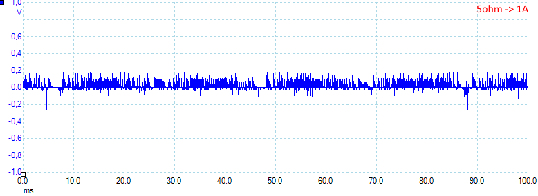
Noise at 1A load is: 36mV rms and 635mVpp.
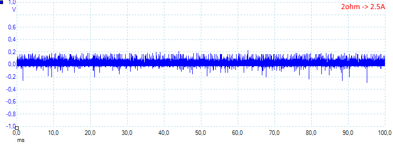
Noise at 2.5A load is: 48mV rms and 688mVpp.
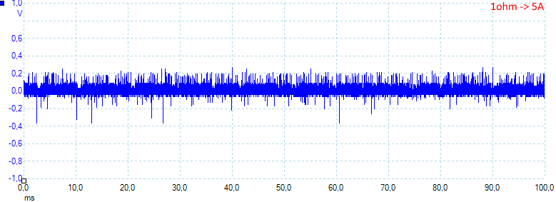
Noise at 5A load is: 68mV rms and 873mVpp.
Tear down
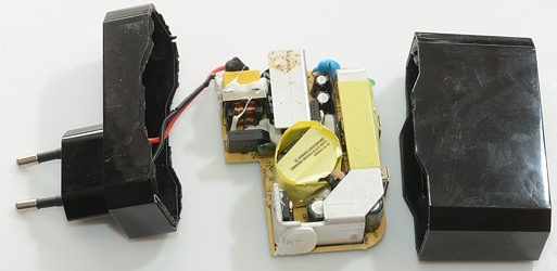
The charger looked easy to open: tie the bottom part in my vice and give the top part a few easy whacks with my mallet. It worked as expected.
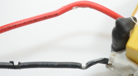
Oops, somebody has been careless when putting this charger together, the black wire has serious damage.
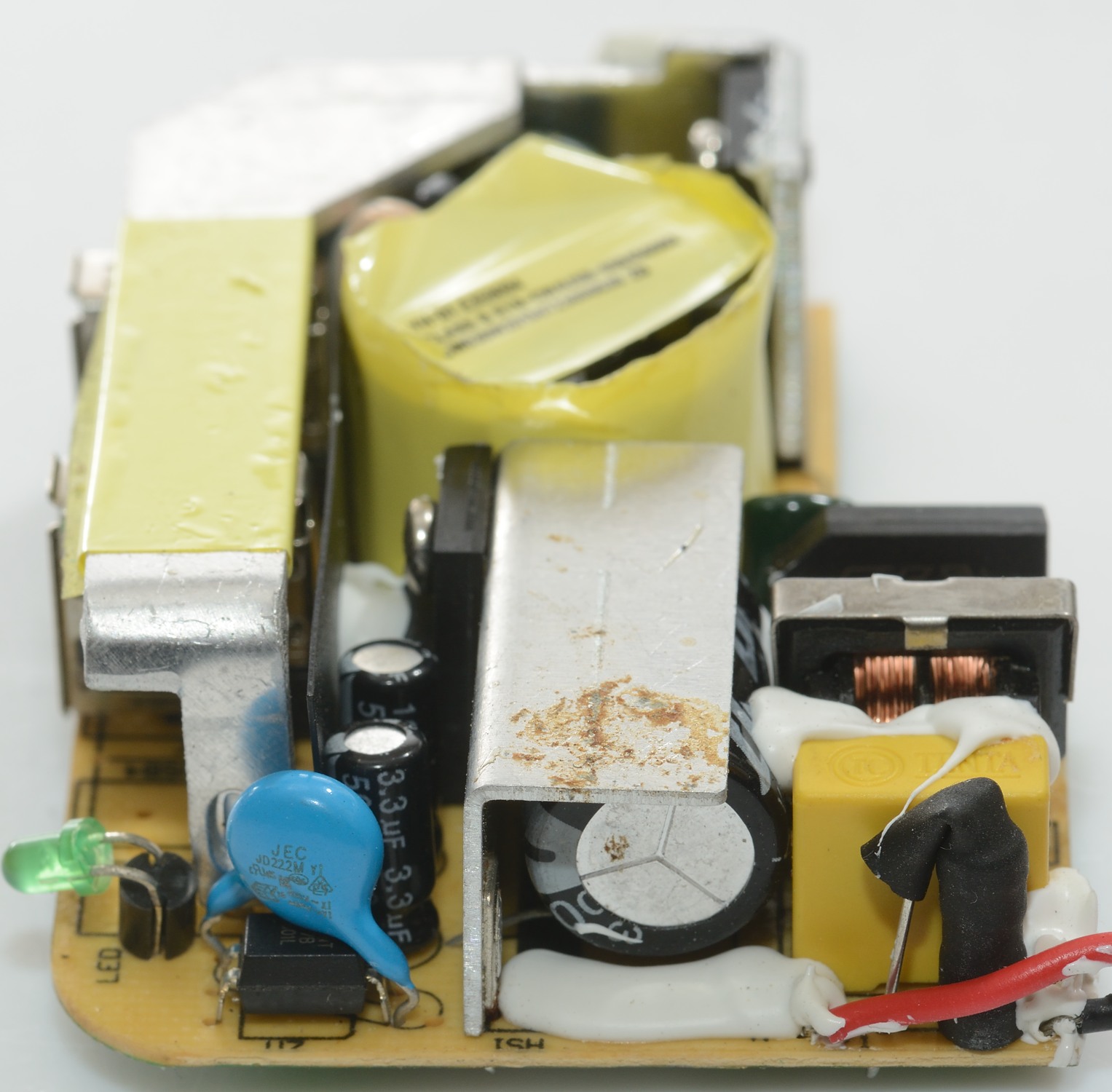
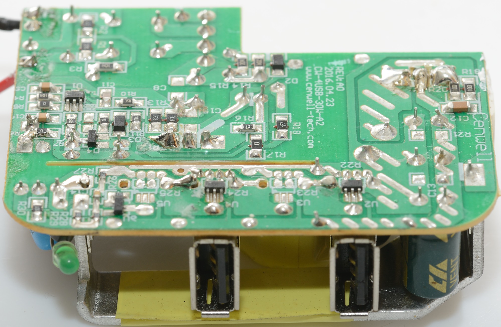
At the mains input there is a fuse and a common mode coil followed by the bridge rectifier. The mains switcher transistor is mounted on a small heatsink.
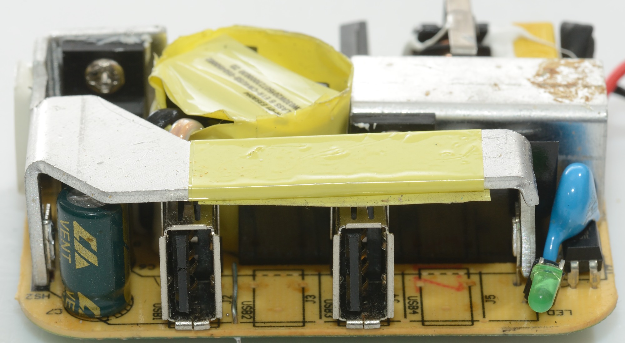
On the low volt side there is the rectifier diode mounted on a long heatsink. At the far end of the heatsink is the opto coupler with the safety capacitor on top and next to that the green led.

One this side the two usb connectors can be seen and space for two more, but the charger do probably not have enough current to handle all four usb connectors at high current.
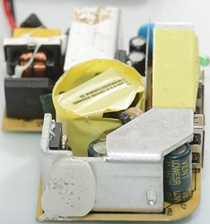
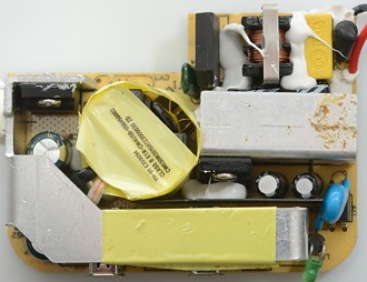
Here the heatsink takes up most of the space, the white blob on it improves heat transfer significantly (Some more would have been a good idea).
I wonder about the rusty look on the heatsink and capacitor, this is not something I expect to see in new electronic.
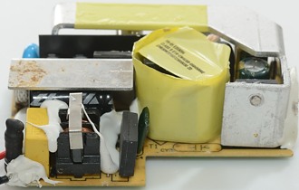
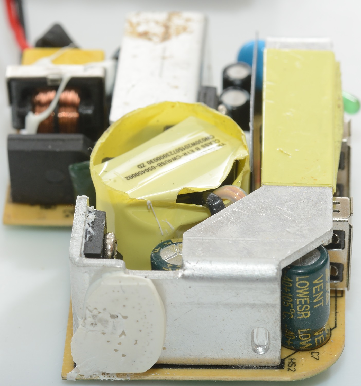
A side view of the fuse, common mode could and bridge rectifier. Besides the transformer is space for an extra safety capacitor.

Here the safety capacitor on top of the opto coupler can really be seen, the circuit board is designed for it.
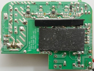
There is some black insulation plastic in a slot on the board, it secures that low voltage is keep well away from mains voltage.
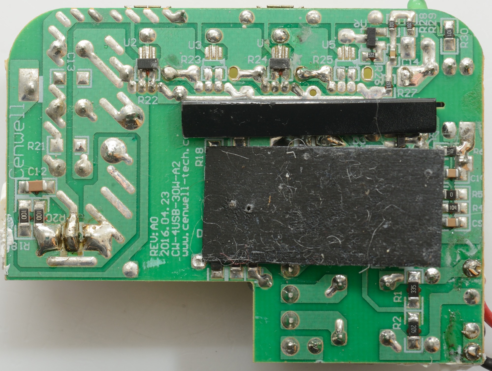
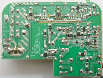
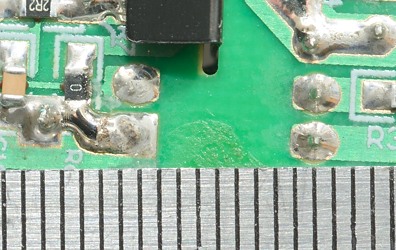
On the mains part of the circuit board is the switcher controller (U1), the low volt side has two usb auto coding chips (U2 & U4) and space for two more (U3 & U5) for the missing usb connectors. The voltage reference is U6.

It looks like there is good isolation distance.
The slot is filled with the plastic piece and there is a very long distance around that.
Testing with 2830 volt and 4242 volt between mains and low volt side, did not show any safety problems.
Conclusion
The charger can supply the rated current without problems, has auto coding and is basically safe. The noise is on the high side, and the overload protection is at a very high level (if it exists), the pinched wire is sloppiness (Maybe someone on the assembly line had a bad day).
Notes
Charger was supplied by Enerpower for review.
Index of all tested USB power supplies/chargers
Read more about how I test USB power supplies/charger
How does a usb charger work?