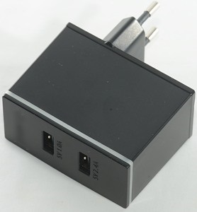
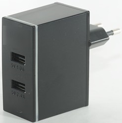
Enerpower Wall adapter EP-L17 2.4A+1A
Official specifications:
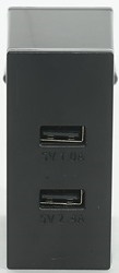
- No. of outputs: 2
- Output: 5 VDC 3.4A 17W
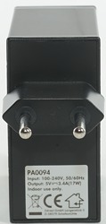
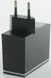
- Voltage: AC 100 - 240 V 50/60Hz
- Max output current per port: 2.4A + 1A
Measurements
- Power consumption when idle is 0.2 watt
- 2.4A usb output is auto code up to Apple 2.4A
- 1A usb output is coded as usb charger (DCP)
- The two output ports are in parallel.
- Weight: 82g
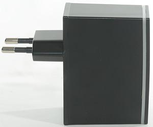
- Size: 88 x 67 x 32.3mm

The 1A port can deliver more than 4A before the over load protection kicks in. This do not look like individual port protection.

The 2.4A port has the same limit.
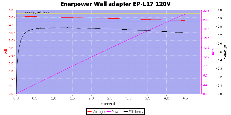
Running both port in paralle also has the same limit (This is not a surprise), here at 120VAC
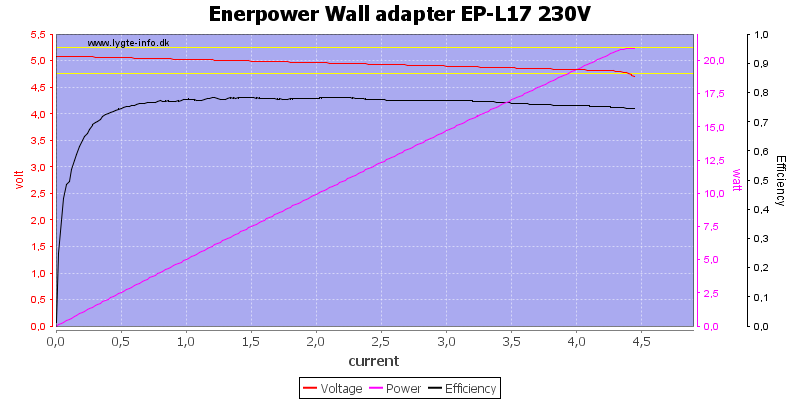
And here at 230VAC
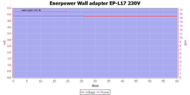
Keeping to rated output power it can easily maintain the output for one hour.
The temperature photos below are taken between 30 minutes and 60 minutes into the one hour test.
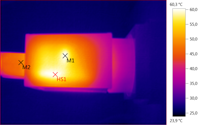
M1: 59,8, M2: 47,9, HS1: 60,3
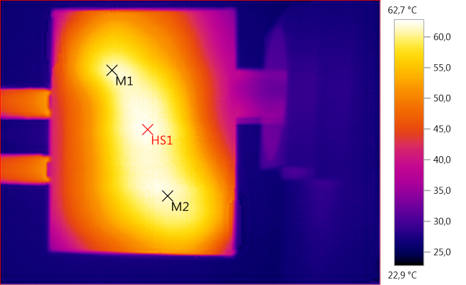
M1: 61,3, M2: 61,6, HS1: 62,7
HS1 looks to the be switcher IC, M2 is the rectifier diode.
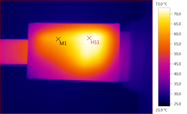
M1: 63,0, HS1: 73,0
HS1 is the rectifier diode.
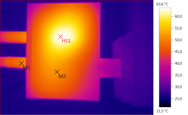
M1: 49,5, M2: 51,4, HS1: 63,6
HS1 is the transformer.
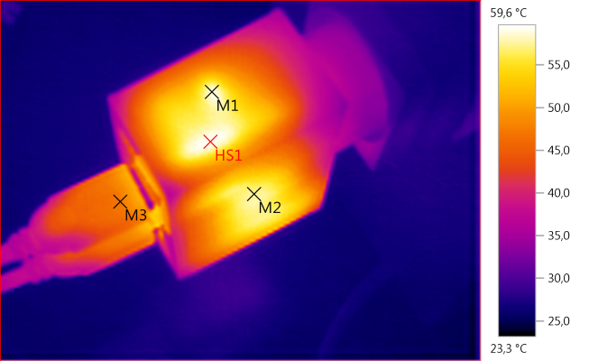
M1: 58,8, M2: 57,4, M3: 47,1, HS1: 59,6
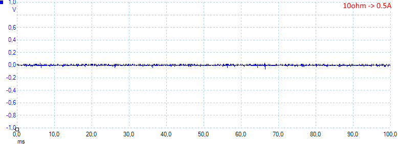
Noise at 0.5A load is: 5mV rms and 81mVpp.
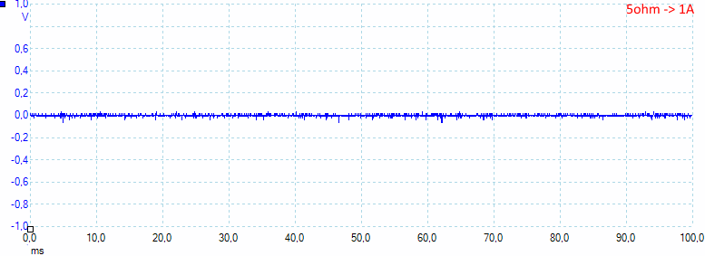
Noise at 1A load is: 55mV rms and 119mVpp.
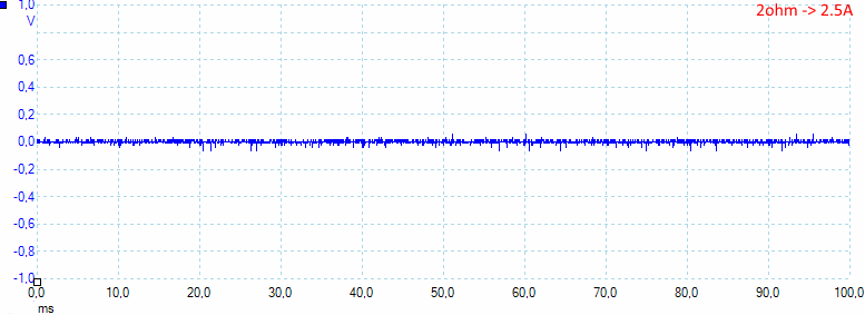
Noise at 2.5A load is: 9mV rms and 138mVpp.
Tear down
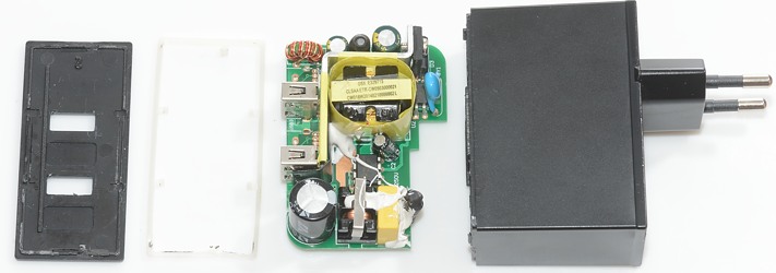
The charger was very easy to open, I just used my nails and pulled the lid off, this is not safe! I would have expected some glue to prevent this.
It must also be possible to open the charger at the bottom (Wires must be soldered from the bottom), but I could not easily remove the bottom.

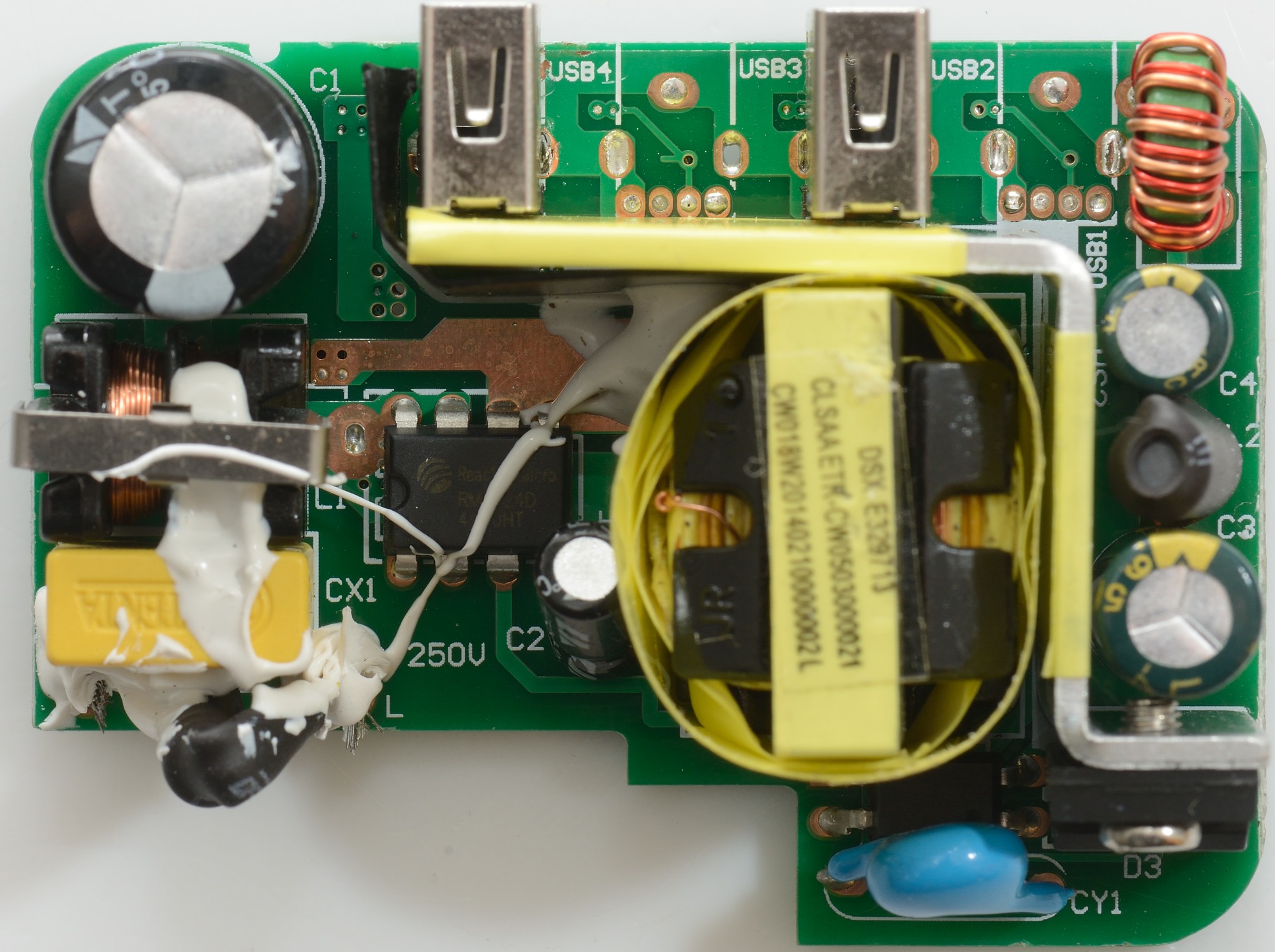
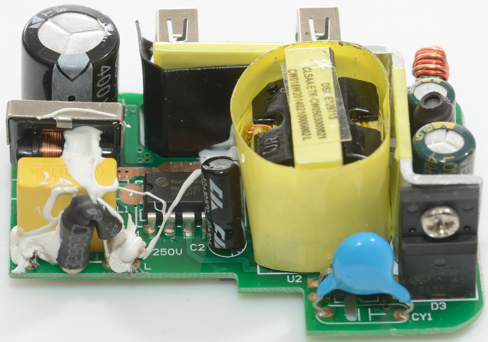
At the mains input is a fuse and a common mode coil. There is no mains switcher transistor, but a single chip that is both the controller and the switcher.
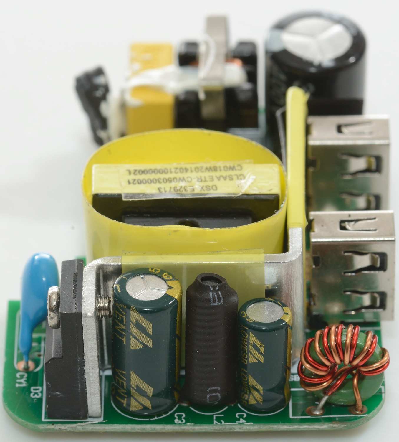
Below the transformer is the opto feedback and the safety capacitor. On the long heatsink the rectifier diode (D3) is mounted. The usb output has a common mode coil.

Here the rectfier diode on the heatsink can be seen, together with a inductor (L2) and a the output common mode coil (L3).

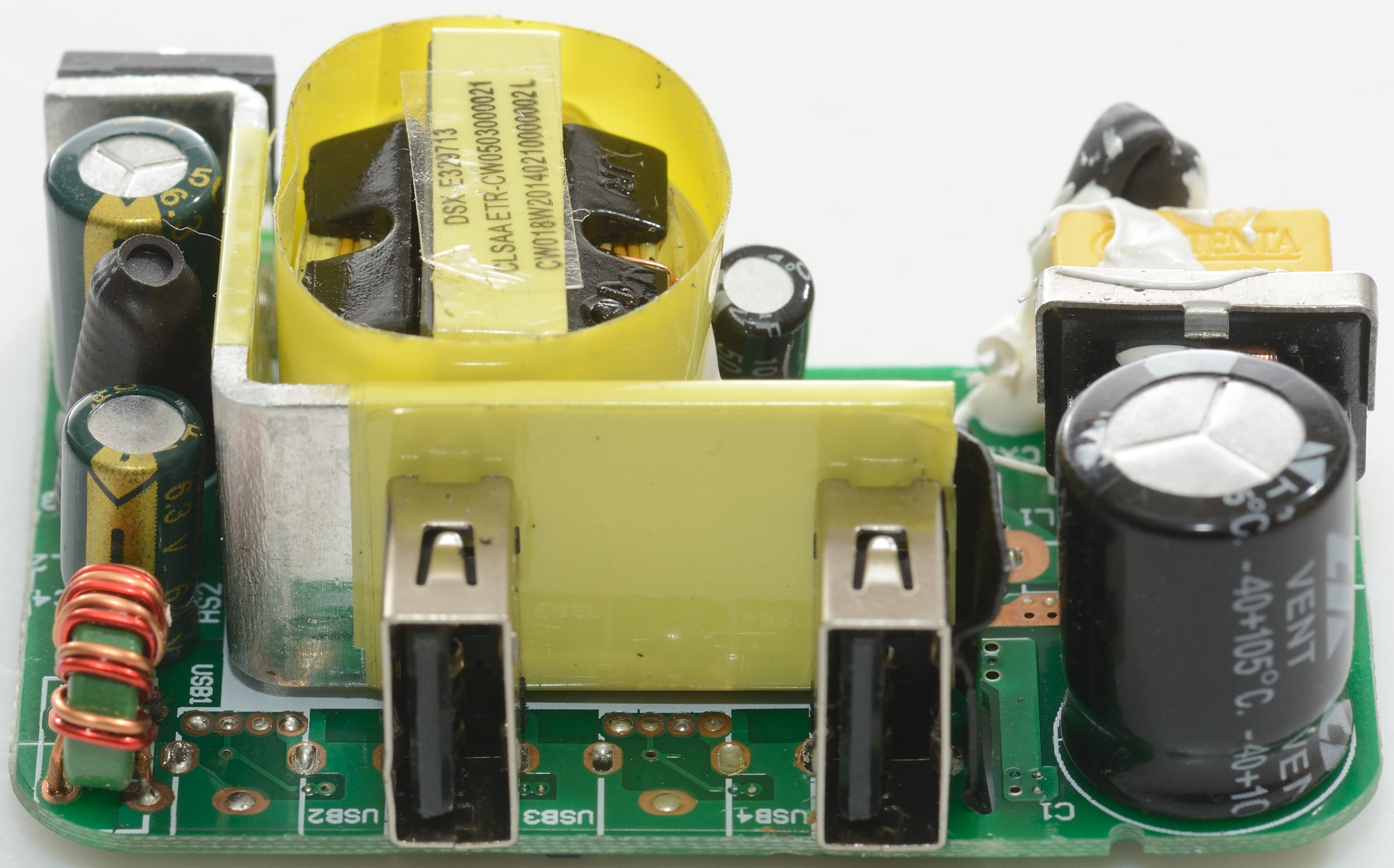
There is space for 4 usb connector, but that would be a rather weak charger.

The fuse covered in heatshrink and the input common mode coil is here.

On this image the switcher is easy to see, it is a RM6224D and is rated for 18W (That is 3.6A at 5V) and works at 65kHz.
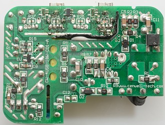
The black isolation is cut on this side, this looks to be due to some service that had to be done after production. It looks sloppy.
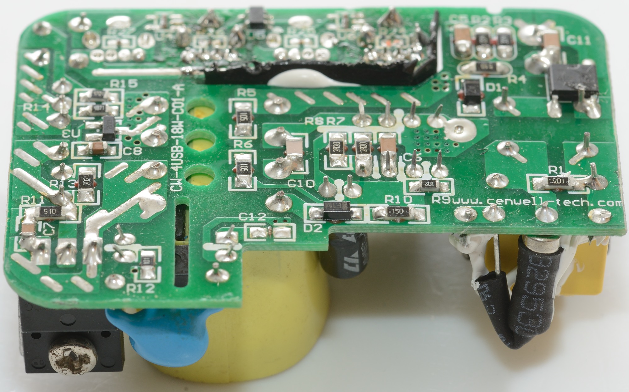
On the mains side is a bridge rectifier and on the low volt side is the usb coding chip (U5) and the voltage reference. There is space for 3 more coding chips (U4, U6 & U7). The first two are not needed and instead of the last one a resistor is used (R24) for fixed DCP coding.

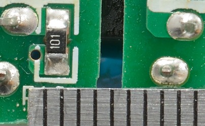
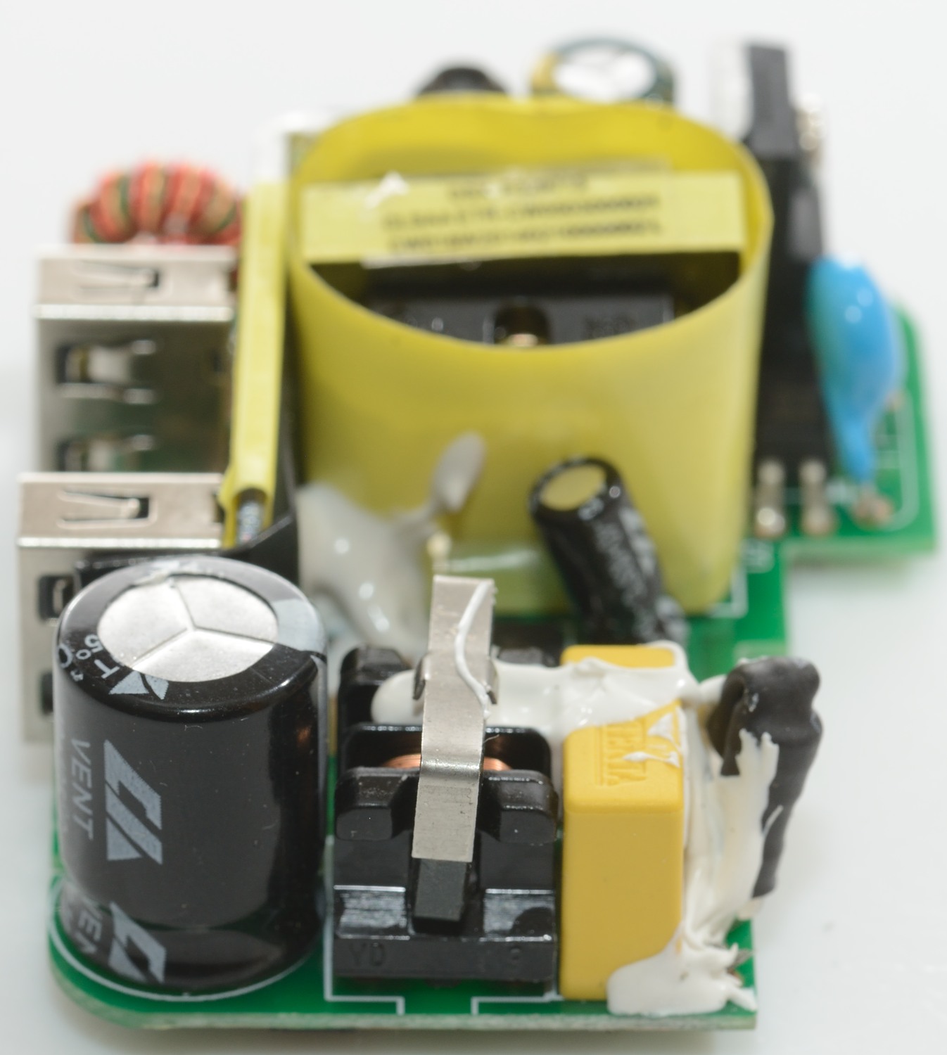
With air isolation (i.e. a slot) the distance only need to be 4mm, again it looks fine.
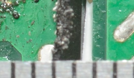
I do not like the cut black plastic, but it do stick about 1.5mm up, i.e. the isolation distance is probably fine.
Testing with 2830 volt and 4242 volt between mains and low volt side, did not show any safety problems.
Conclusion
The charger can supply the rated current without problems, has auto coding on one output and low noise. Becuase the lid could easily be removed it is not safe (I expect that to be a production fault).
Notes
Charger was supplied by Enerpower for review.
Index of all tested USB power supplies/chargers
Read more about how I test USB power supplies/charger
How does a usb charger work?