HTC TC EC250
This is an 5V 1A rated usb power supply/charger.
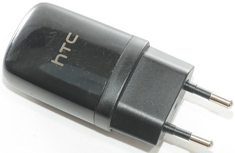
This charger is a older good quality charger from a name brand, use this review to see how it is build and compare performance to the cheap brands I test.
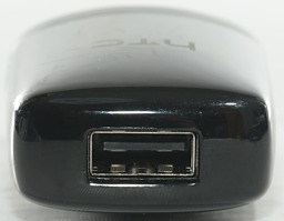
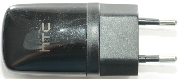
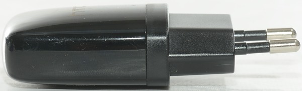
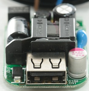
A compact and rounded design with the USB connector in the center.
Measurements
- Idle power 0.04 watt
- The charger will reduce current and voltage if the load is above 1.6A
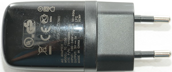
- Output is coded as USB charger (DCP).
- Difficult to open (This is good).
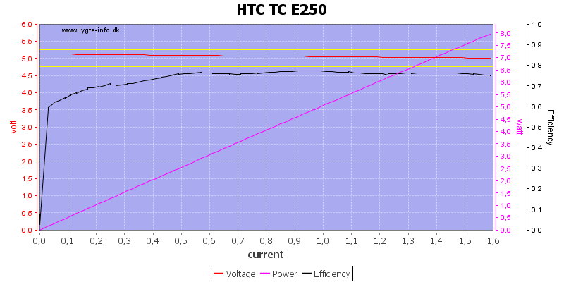
Output voltage is very stable and the efficiency is around 75%, the charger has overload protection at 1.6A. I believe that is rather high for a 1A charger.
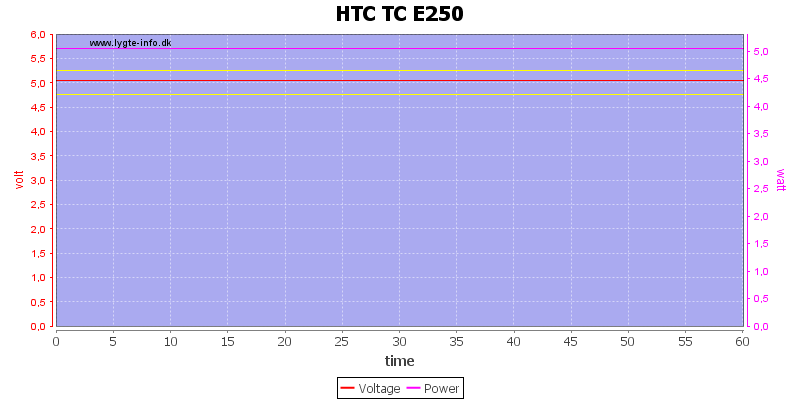
One hour with 1A load is not problem.
The temperature photos below are taken between 30 minutes and 60 minutes into the 1 hour test.
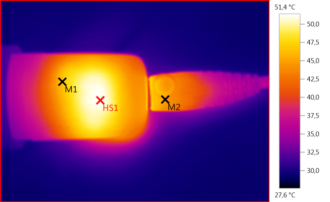
M1: 46,5°C, M2: 44,7°C, HS1: 51,4°C
The warm spot here is probably the transformer and it is not very warm.
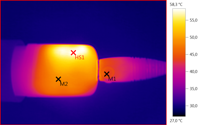
M1: 43,8°C, M2: 48,8°C, HS1: 58,3°C
This is the diode D101 and also some heat from the control ic, that is mounted below one of the capacitors.
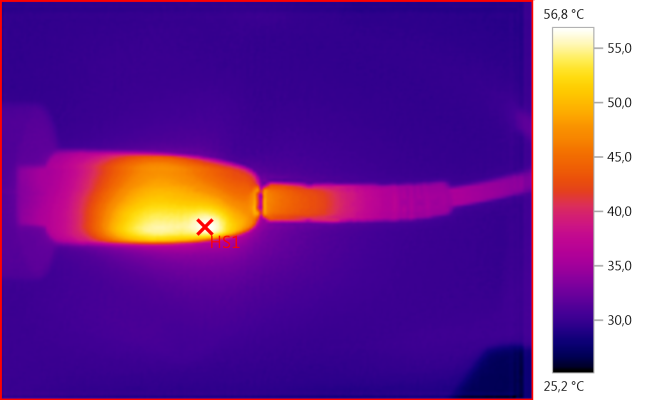
HS1: 56,8°C
Here the diode is HS1 and the other warm part is the control ic.
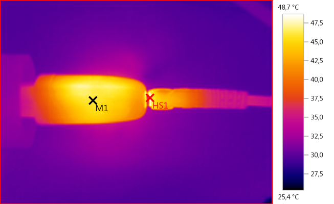
M1: 45,9°C, HS1: 48,7°C
The usb connector is slightly hotter than the case here, probably because it is heated by the diode.
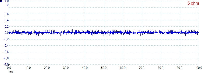
There is not much noise, 18mV rms and 240mVpp. at 1A.
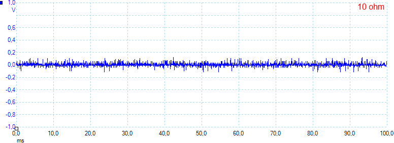
At 0.5A the noise is about the same with 17mV rms and 260mVpp.
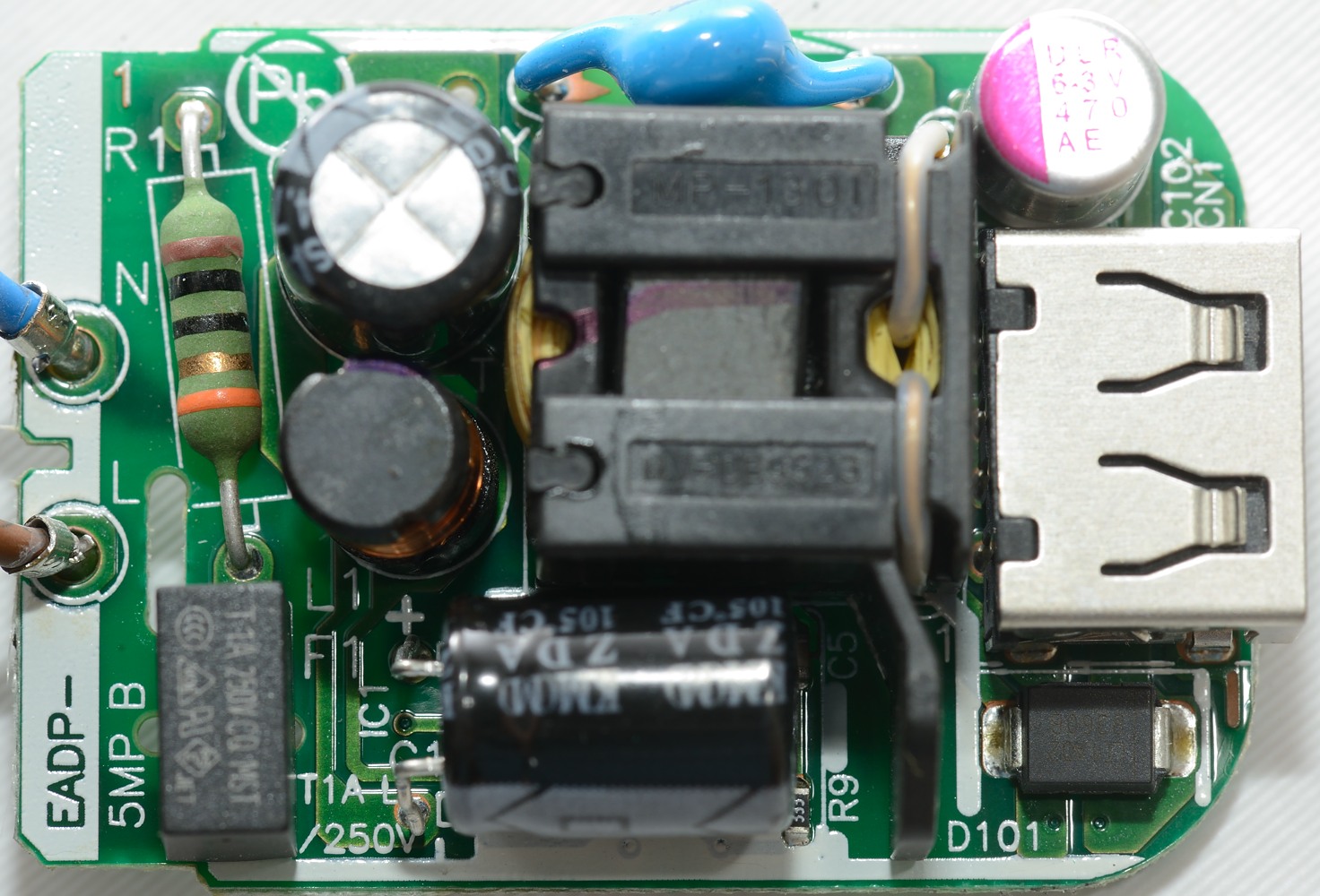
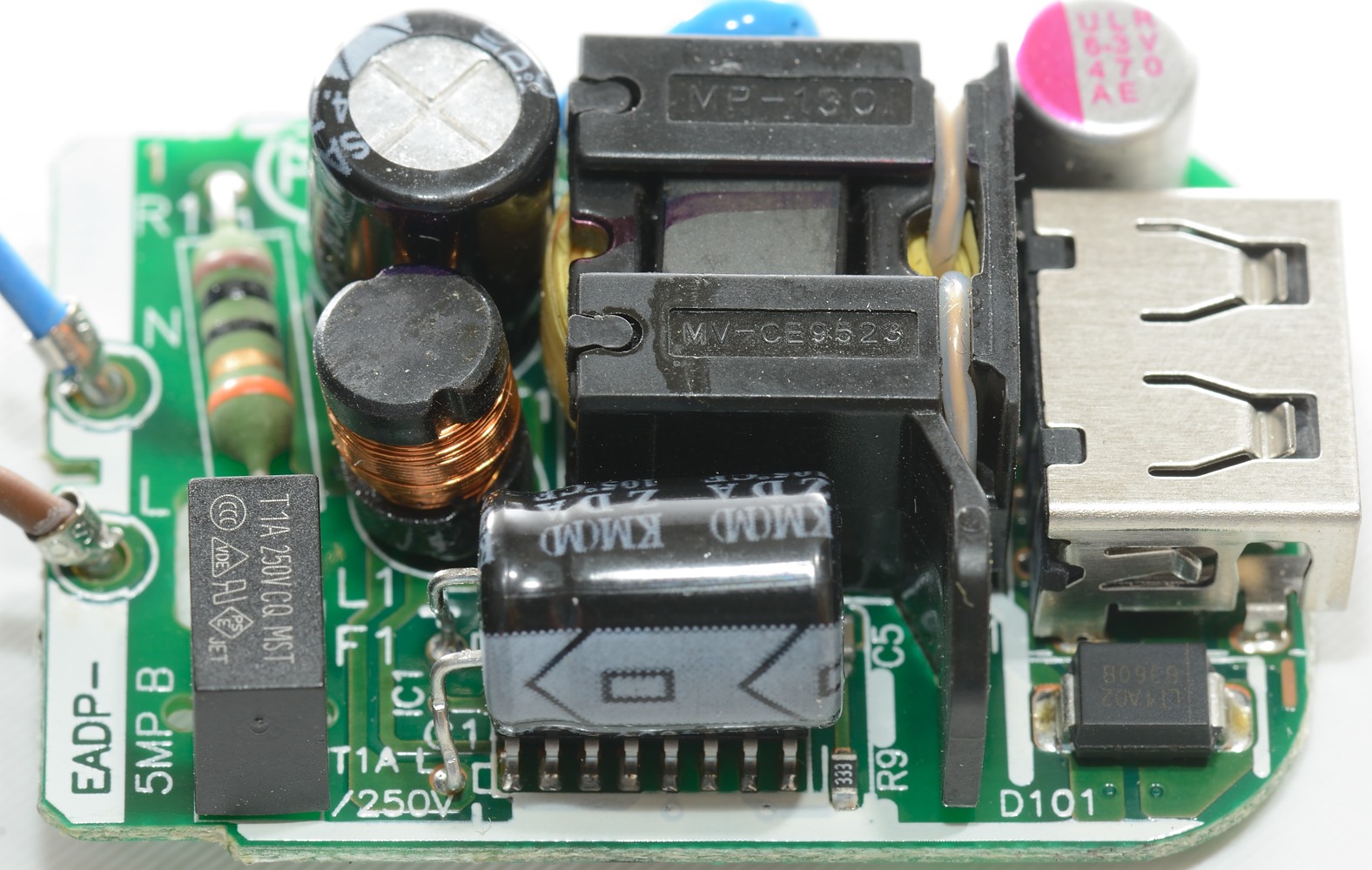
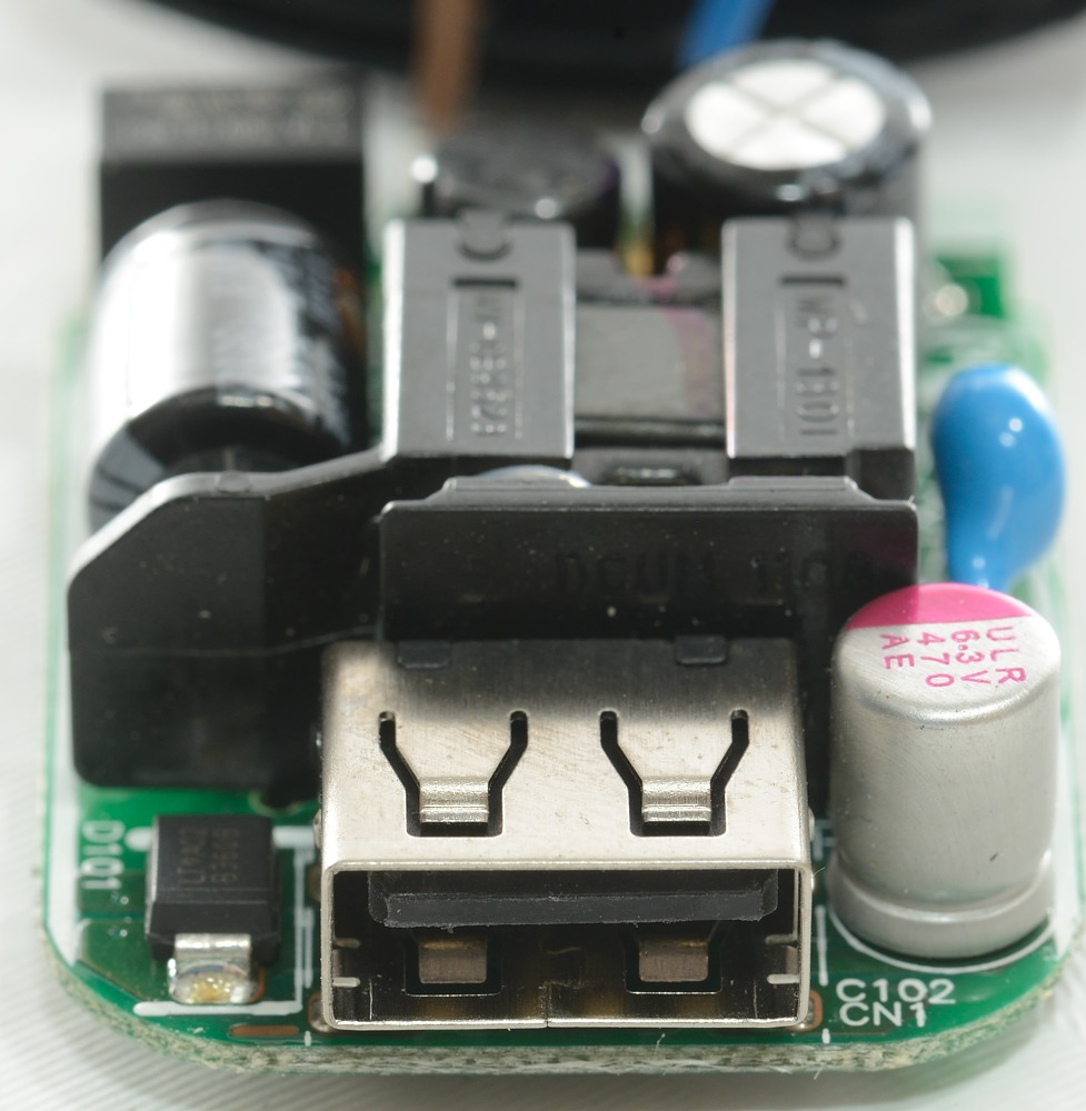
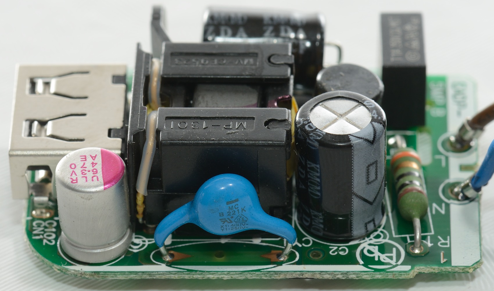
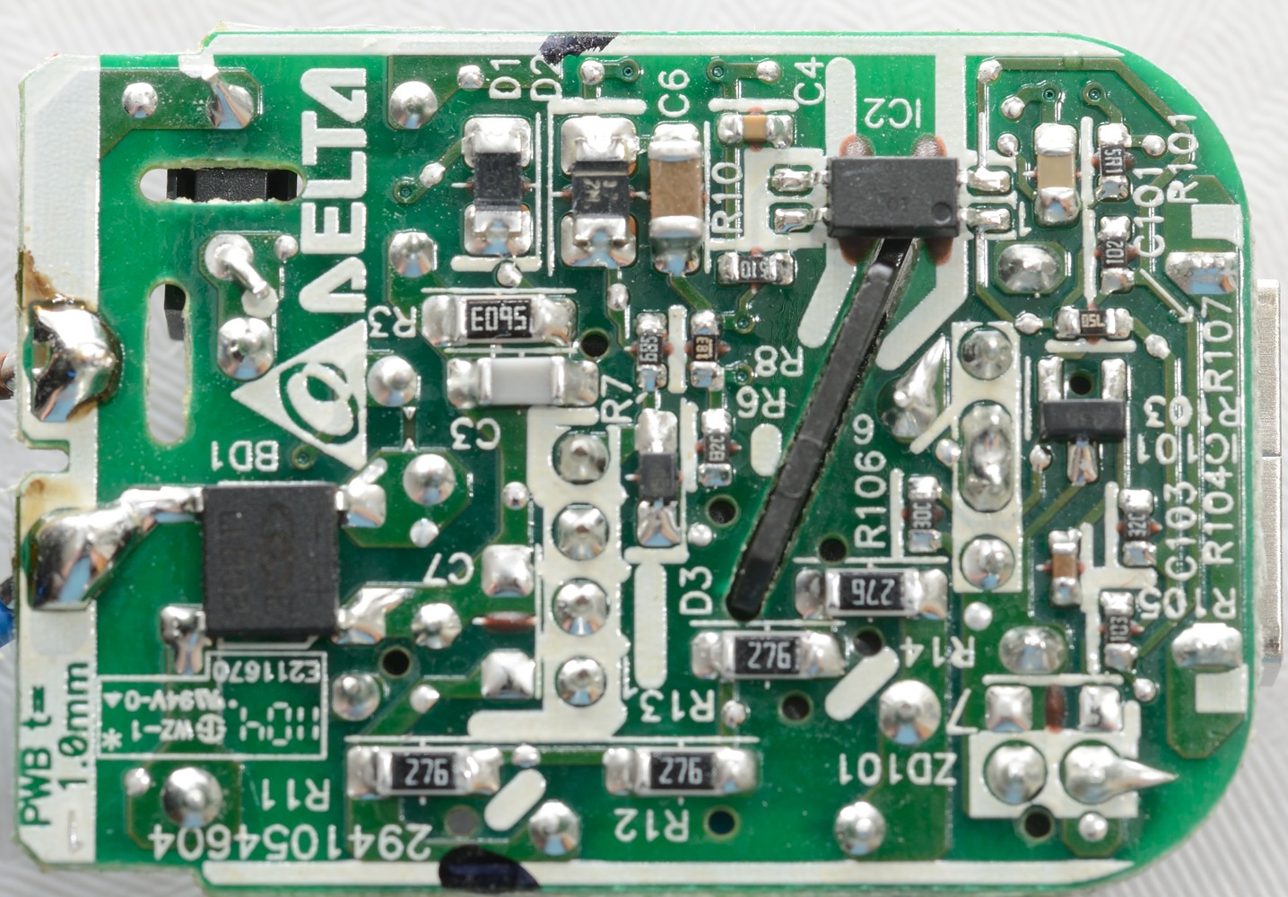
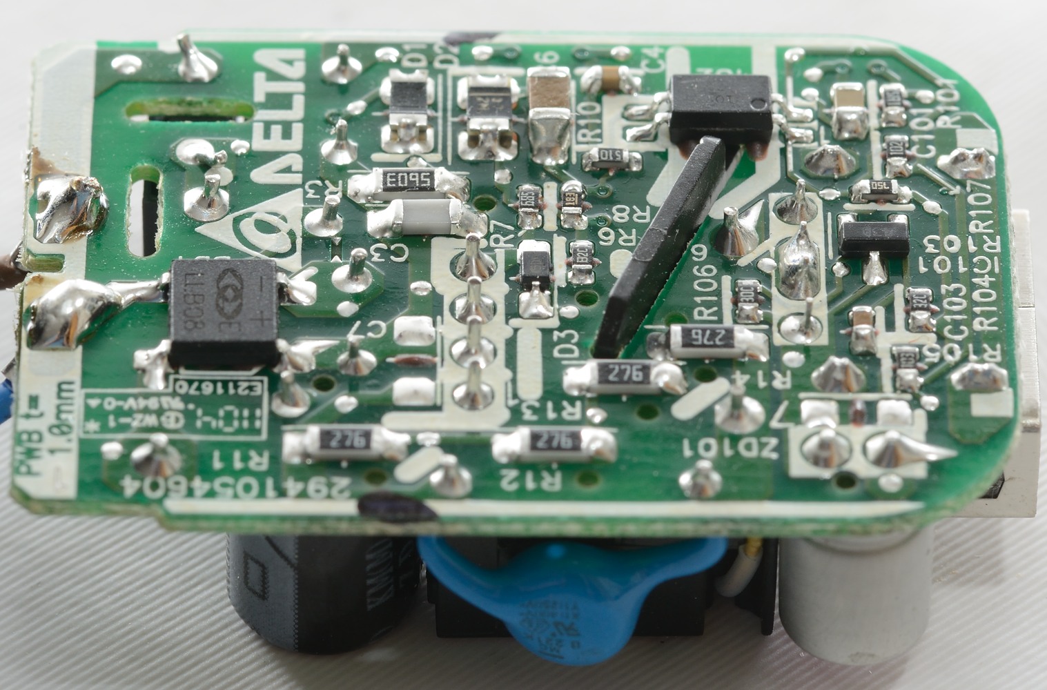
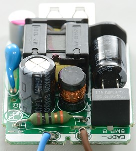
Tear down
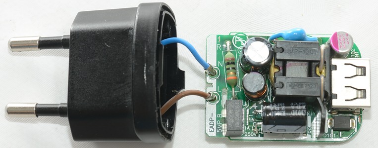
The wires from the plug is not soldered directly in the circuit board.

The main capacitors has a 105°C temperature rating, this is good.

There is a plastic shield on the transformer and it has a wing that prevents the capacitor to touch the low volt side, even if there is a very hard bump.
There is a fuse on the mains side, this can prevent a fire if the control chip fails.

The blue capacitors looks like a safety capacitor.
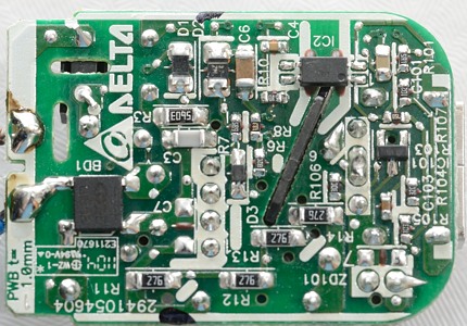
BD1 is a bridge rectifier.
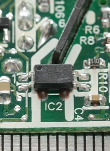
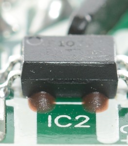
IC2 is an opto coupler, to give feedback about the output voltage.

The shield on transformer goes through the circuit board and is used to increase distance between mains and low volt side. This way the charger can be more compact, but still have enough isolation distance.
The electric connections are placed outside the thick white lines, to give enough distance.
The red stuff is probably to increase isolation.
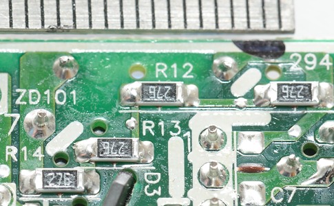
A interesting detail, there is a four resistors between the mains and the low volt side, each is 27Mohm. This is completely safe, but I wonder why they have it.
Testing the mains input with 2500 volt and 5000 volt between mains and low volt side, did not show any safety problems.
Conclusion
It is interesting to see how a big brand usb power adapter works. There as not really anything to complain about in it.
Notes
The power supply was supplied by Erik from Finland for review.
Read more about how I test USB power supplies/charger