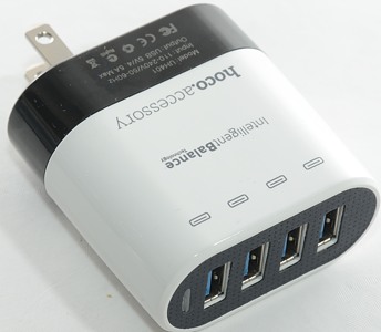
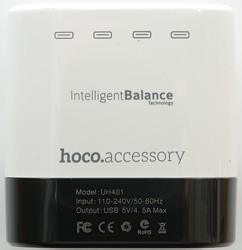
Hoco 4 port usb 4.5A UH401
Official specifications:
- Brand Name: HOCO
- Model: UH401
- Type: Travel Fast Charger
- Material: ABS+PC
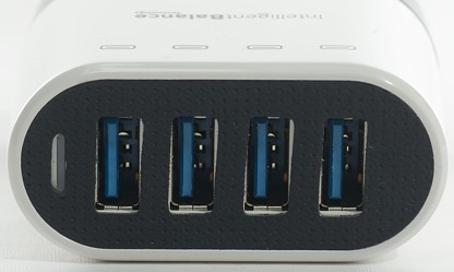
- Smart Identify: Intelligent Balance technology
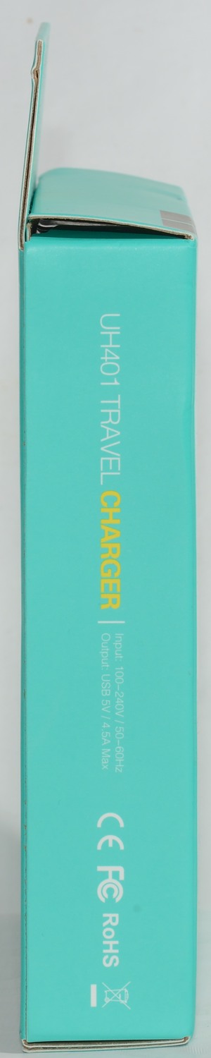
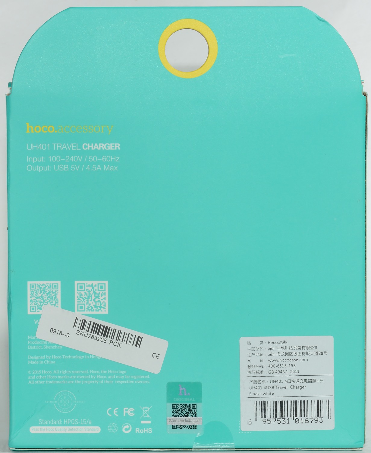
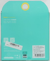
- Input: AC110V-220V
- Total Output: DC 5V/4.5A 22.5W
- One Plug Output: DC 5V/2.4A (the largest)
- Certificate: CE/FCC/RoHS
- Weight: 85g
- Dimension: 28 x 59 x 62mm
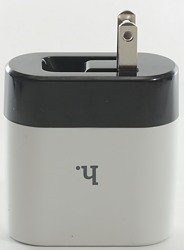
- Color: White+Black
I got it from Banggood


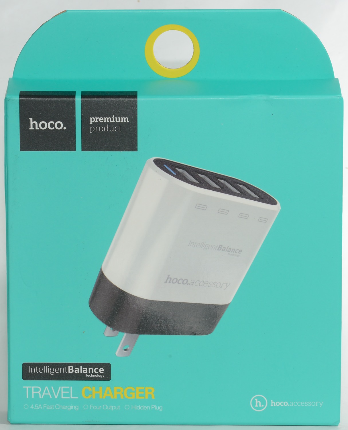
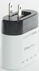
I got this charger in a cardboard retail box.
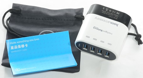
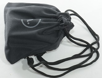
The box contained the charger, a pouch and a note.
Measurements
- Power consumption when idle is 0.4 watt
- Usb port coding is automatic selected (Up to Apple 2.5A).
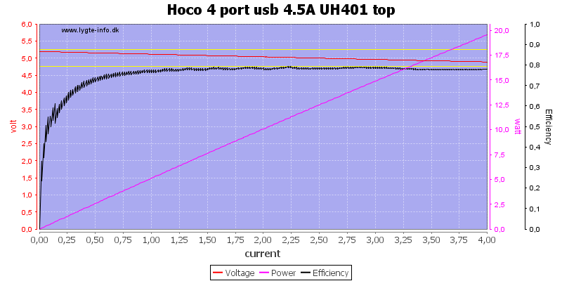
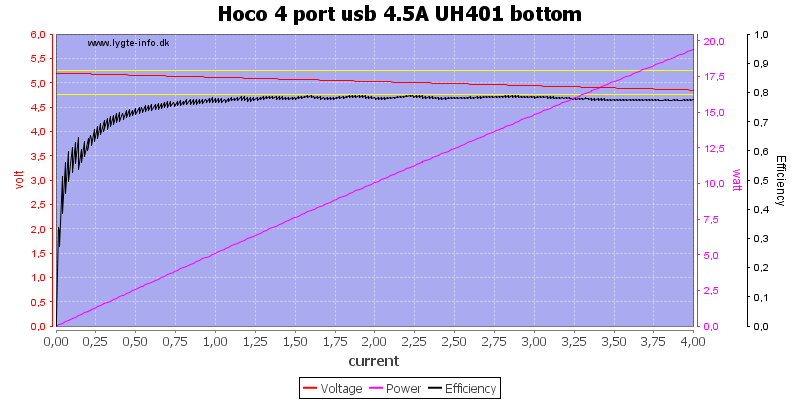
The top and bottom output looks just about the same, this also shows that there is no individual port protection.
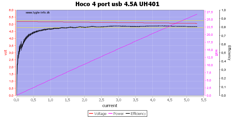
Linking all ports together and increasing the current shows that there is a common overload protection slightly above 5A, this is a good value for a 4.5A charger.
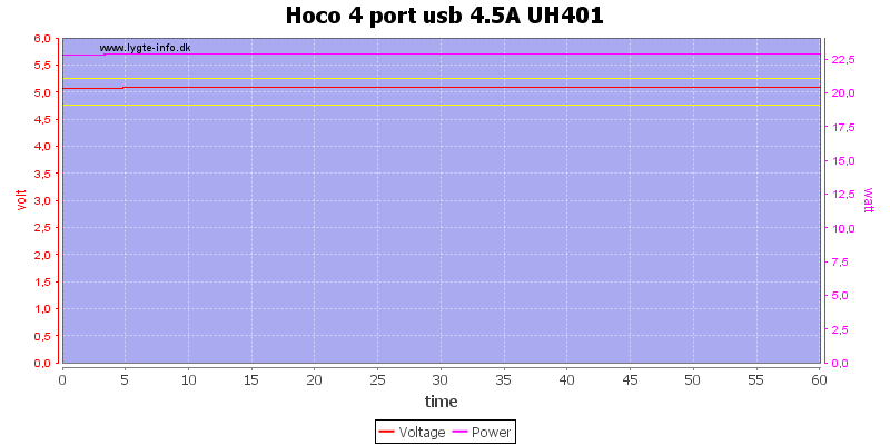
There is not problem delivering 4.5A for an hour.
The temperature photos below are taken between 30 minutes and 60 minutes into the one hour test.
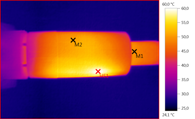
M1: 49,5°C, M2: 50,7°C, HS1: 60,0°C
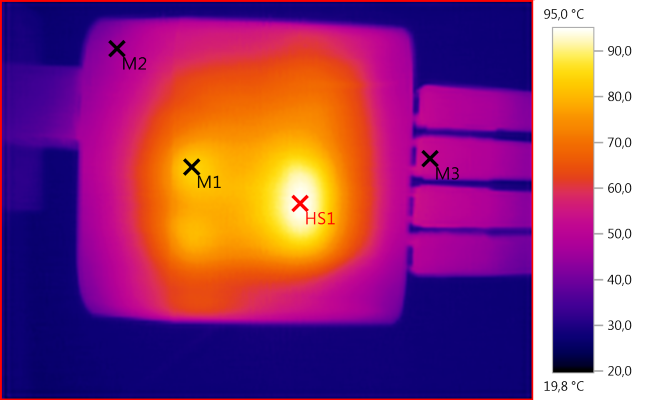
M1: 84,1°C, M2: 46,0°C, M3: 51,9°C, HS1: 95,0°C
HS1 is the 3 diodes under the metal, M1 and the heat below it is D5 and D6
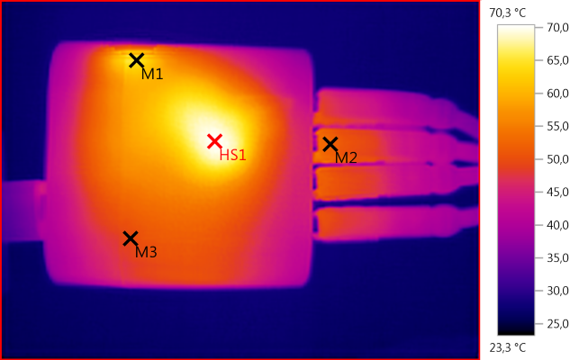
M1: 64,9°C, M2: 52,4°C, M3: 49,6°C, HS1: 70,3°C
HS1 is the transformer.
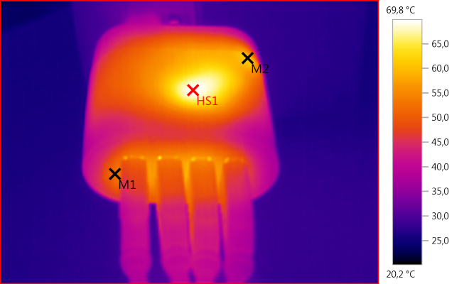
M1: 52,1°C, M2: 62,0°C, HS1: 69,8°C
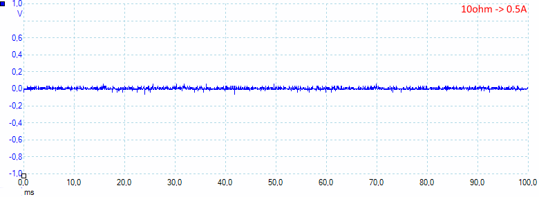
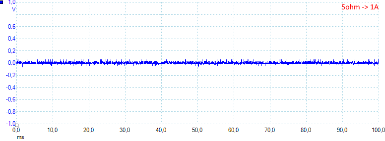
The noise is low at 8mV rms and 100mVpp
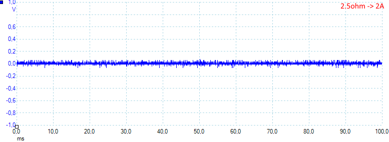
Increasing the load will also increase the noise: 11mV rms and 130mVpp
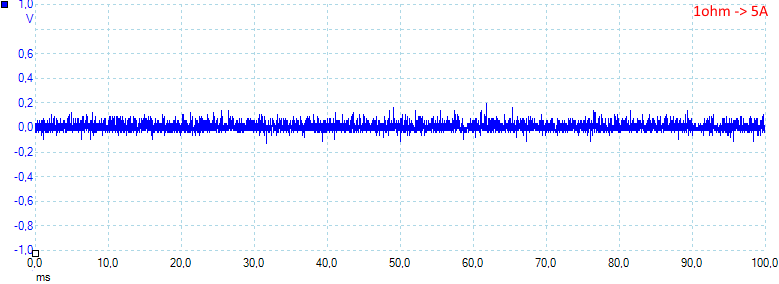
As above: 15mV rms and 160mVpp
With a slight overload the noise is still at a fairly low value: 29mV rms and 340mVpp
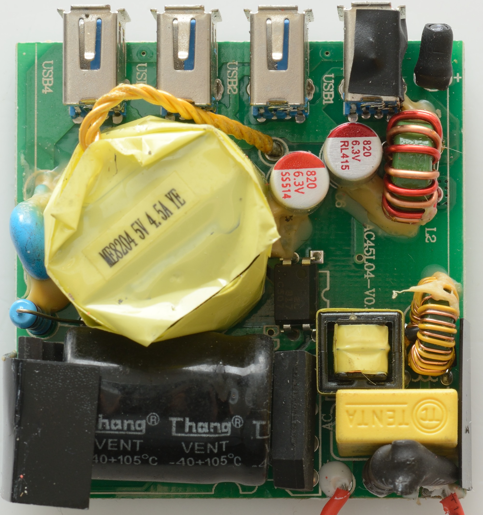
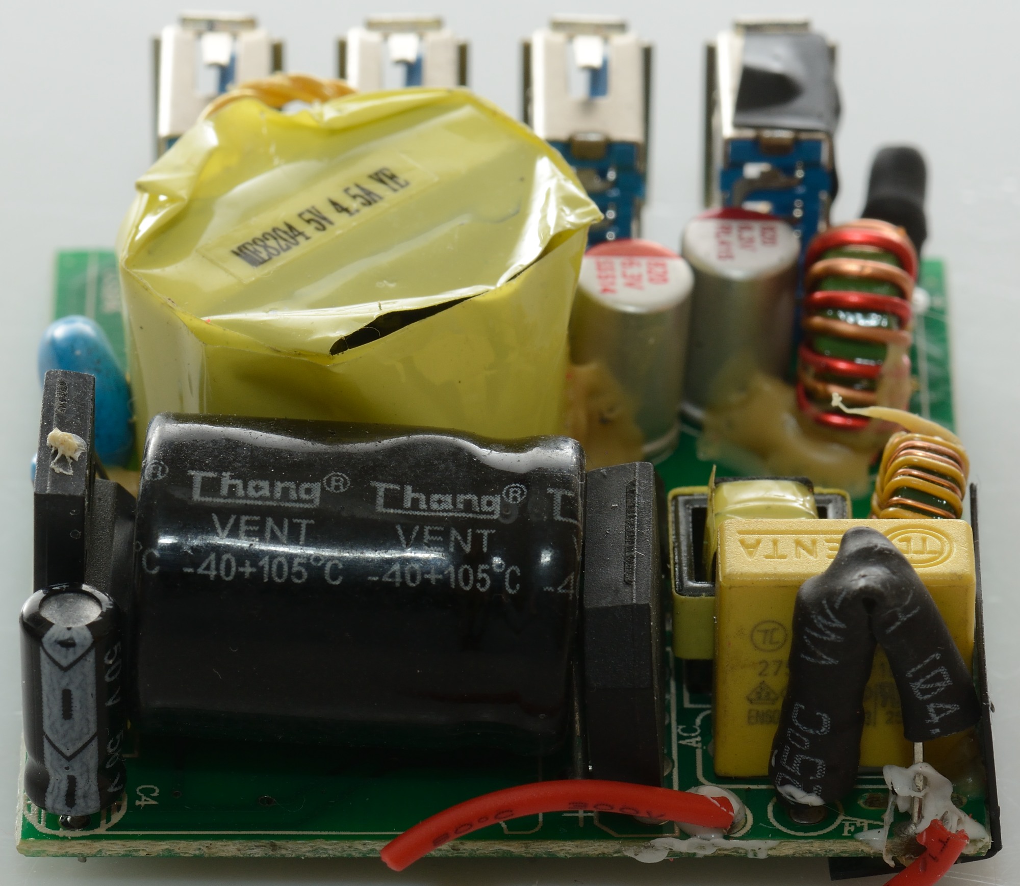
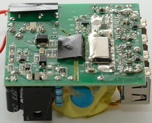
Tear down
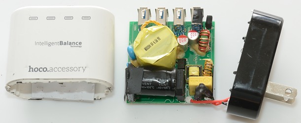
I needed both my vice and a mallet to open this.
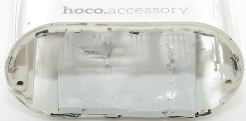
Notice the rubber at the bottom, it could be to reduce rattling noises, but my guess is that it is used to improve heat transfer (Thermo photo that hits 95,0°C).

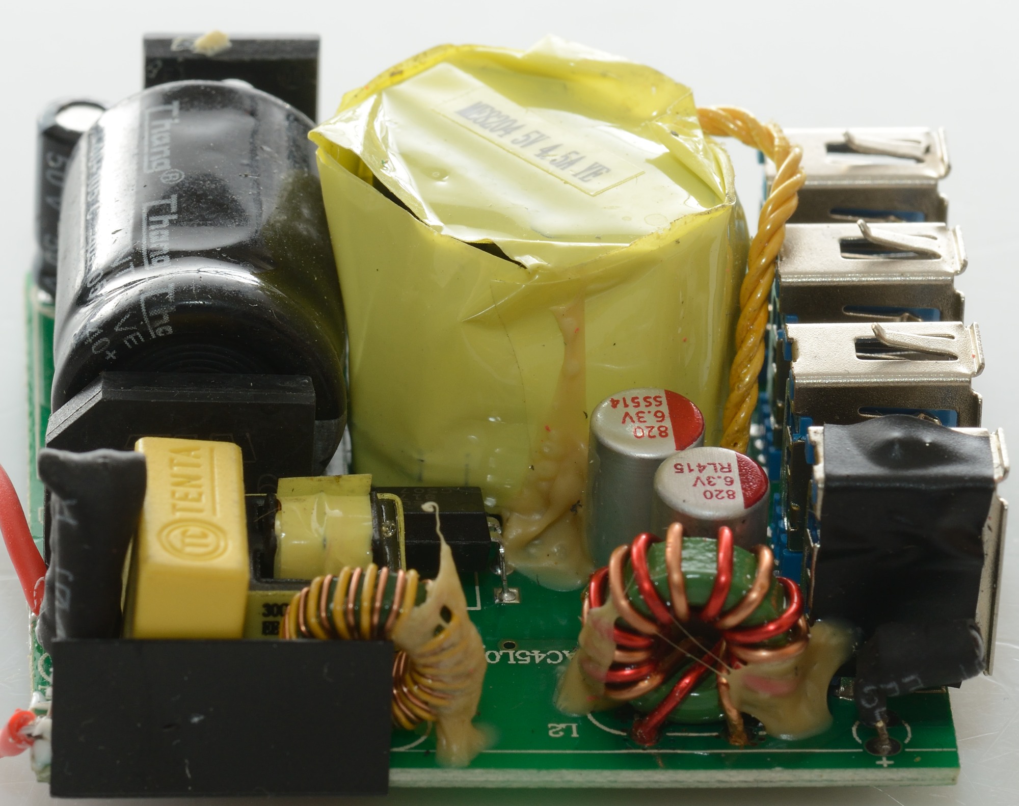
On the topside there is a fuse where the mains is connected and 3 common mode coils, two on the mains side and one on the low volt side. There is also a bridge rectifier, opto feedback and a safety capacitor and below some paper is the mains switcher transistor.

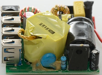
From this side the fuse can be seen between the two red wires and the bridge rectifier at one end of the large mains capacitor.
On the other view the mains switcher transistor and the safety capacitor can be seen.


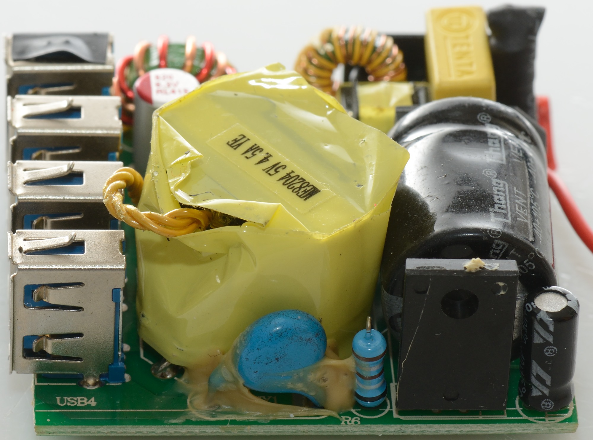
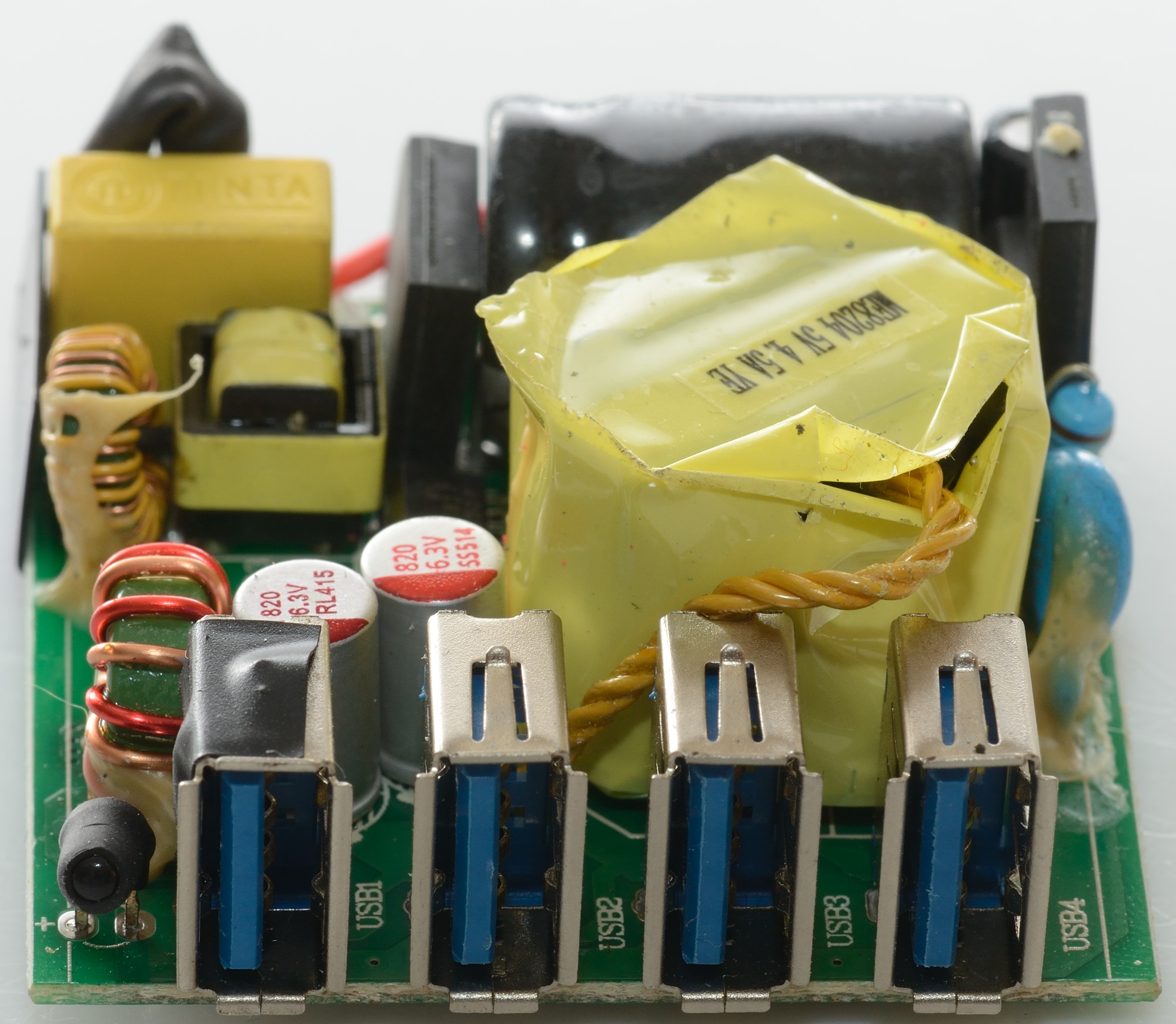
Usb connectors and the blue led with shrink wrap around to avoid light spill into the usb connectors.
The other view shows all the common mode coils, one looks like a small transformer the other two are on toroidal.
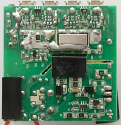
The bottom of the circuit board has the mains switcher controller (U1), the voltage feedback controller (U3) and two auto coding chips (U4, U5). The metal shields has 3 rectifier diodes in parallel (D1, D2, D3).
The black pieces is (special) paper, that is used to improve the isolation.
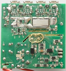
This view gives a better impression of the paper and the metal shield.

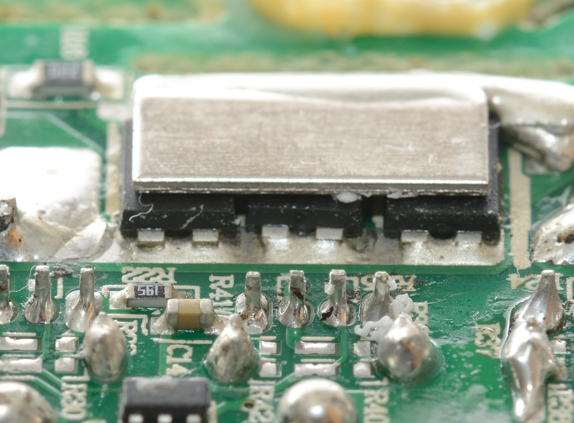
A closer look at the metal shield and the 3 diodes.
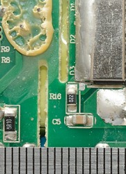
The isolation distance is generally good, but the black paper is needed.
Testing with 2500 volt and 5000 volt between mains and low volt side, did not show any safety problems.
Conclusion
Generally the charger looks good, but I am a bit worried about the high temperature when running at full load (That is only relevant for people that will run it at full load).
Notes
Index of all tested USB power supplies/chargers
Read more about how I test USB power supplies/charger