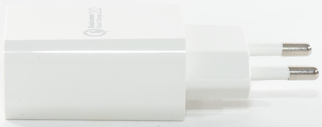
IKX 1 USB Quick Charge PT01
Official specifications:
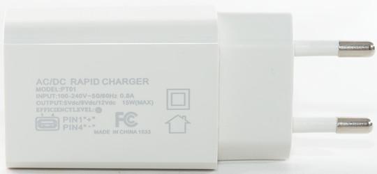
- Input: 100 - 240V 50 / 60Hz 0.8A
- Working power: 15W (Max.)
- Output: DC 5V / 9V / 12V
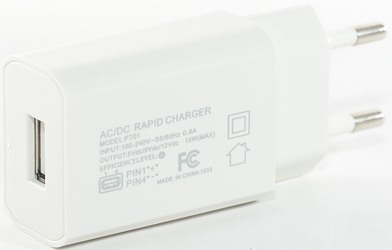
- Type: Power Adapter
- Compatible Devices: Universal
- Special Functions : Portable,USB,Rapid Charging
- Color: Black,White
- Package weight: 0.063 kg
- Product size (L x W x H): 8.200 x 3.900 x 2.200 cm / 3.228 x 1.535 x 0.866 inches
I got it from Aliexpress dealer: China Brands AE Technology Co., Ltd. (price was below $4 including shipping).
Measurements
- Power consumption when idle is 0.13 watt
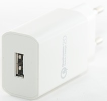
- Usb output is coded as QuickCharge
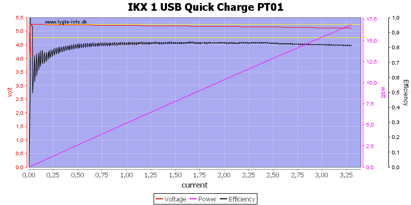
The adapter is rated for 15W output and it delivers it, even at 5 volt and with over current protection.
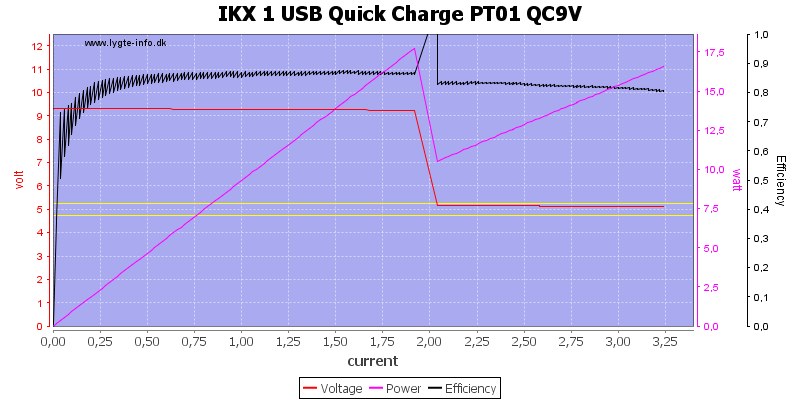
Again it delivers the rated power.
Note: I have cleaned the curve where it drops from 9V to 5V, the voltage goes to 0V for a short time.
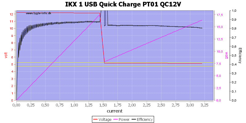
And also at 12V. it looks like the limit is power based and probably part of the mains switcher.
Note: I have cleaned the curve where it drops from 12V to 5V, the voltage goes to 0V for a short time.
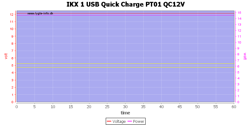
Delivering the rated 15W for 1 hour is no problem.
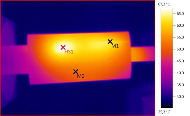
The temperature photos below are taken between 30 minutes and 60 minutes into the one hour test.
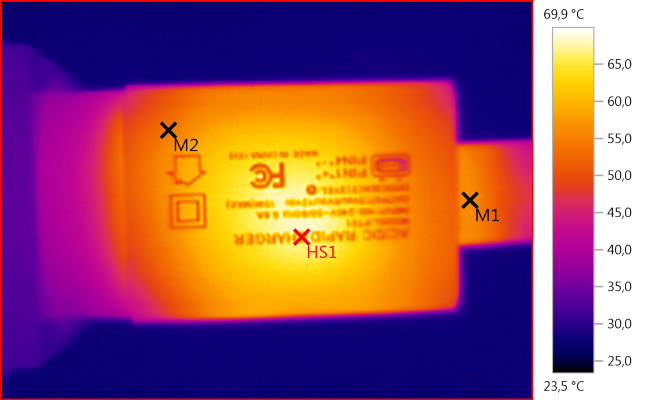
M1: 56,1°C, M2: 54,2°C, HS1: 69,9°C
HS1 is the mains transformer.
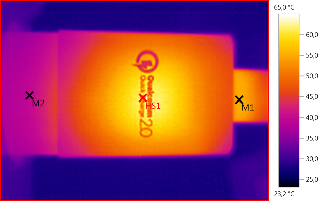
M1: 62,2°C, M2: 52,1°C, HS1: 67,3°C
Here HS1 is the mains switcher transistor.
M1: 54,9°C, M2: 40,0°C, HS1: 65,0°C
Again HS1 is the mains transformer.
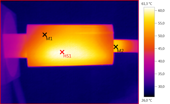
M1: 48,7°C, M2: 55,4°C, HS1: 61,3°C
HS1 is the circuit board, probably heat from the rectifier diode.
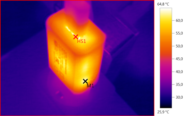
M1: 63,0°C, HS1: 64,8°C
It must also be the rectifier diode that heats the usb connector.
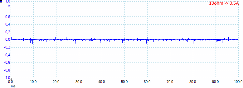
Noise at 0.5A load is 10mV rms and 388mVpp
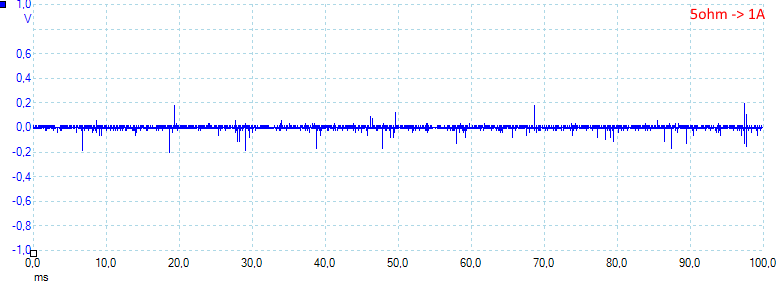
Noise at 1A load is 15mV rms and 503mVpp
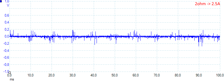
Noise at 2.5A load is 20mV rms and 530mVpp
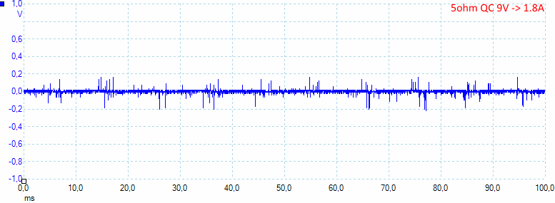
Noise at 9V 1.8A is 20mV rms and 520mVpp
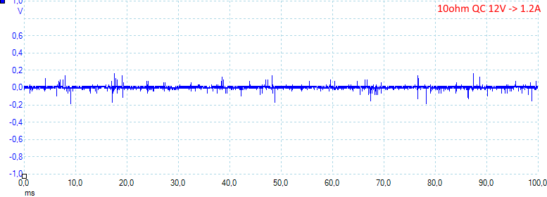
Noise at 12V 1.2A load is 16mV rms and 440mVpp
Tear down
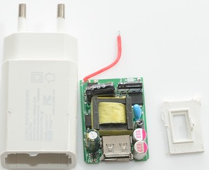
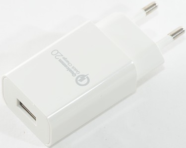
The adapter was clicked together and I could break it open with a screwdriver.
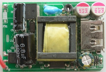
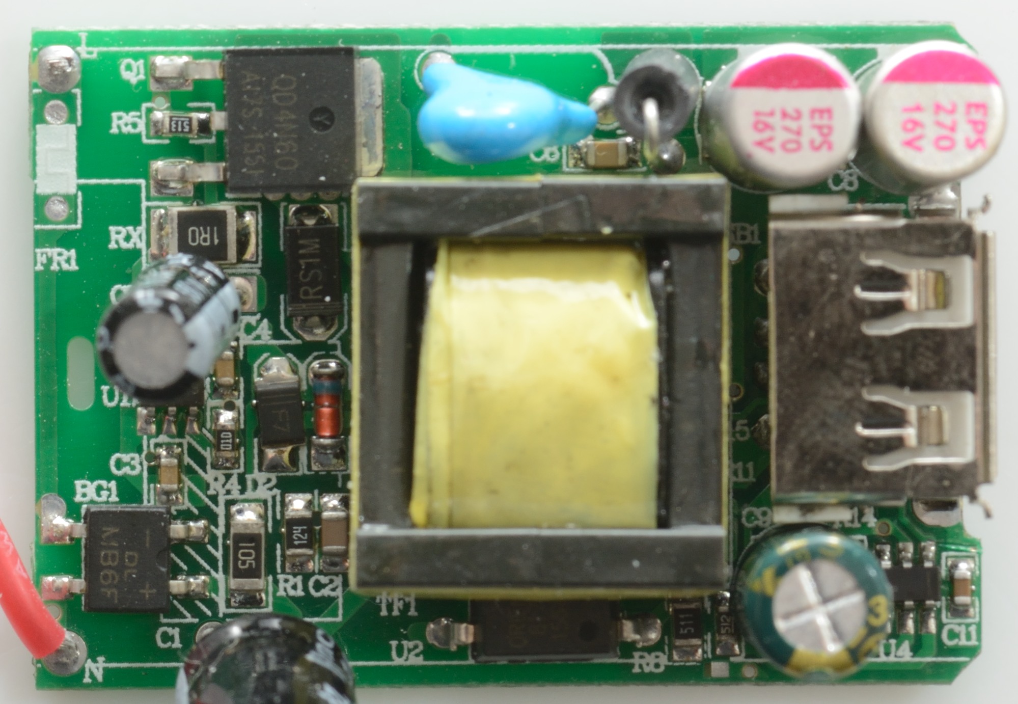
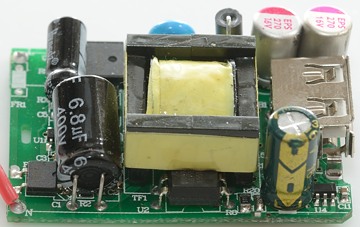
There is space for an input fuse (FR1), but it is missing. After the fuse is the bridge rectifier (BG1). There is a fairly large mains switcher transistor (Q1). Just beside the transistor is the safety capacitor, on the other side of the mains transformer is the opto coupler. Beside the usb connector is a 6 pin chip (U4), it must be the quick charge controller.
I am missing the rectifier diode, it must be placed below the transformer.
Below the capacitors is a couple more parts, including the mains switcher controller (U1).
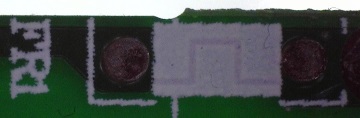
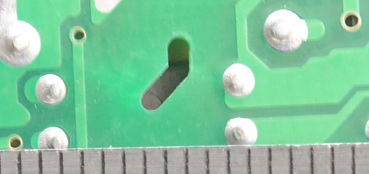
There is a "fuse", it is made with a thin trace on the circuit board, under the white paint.
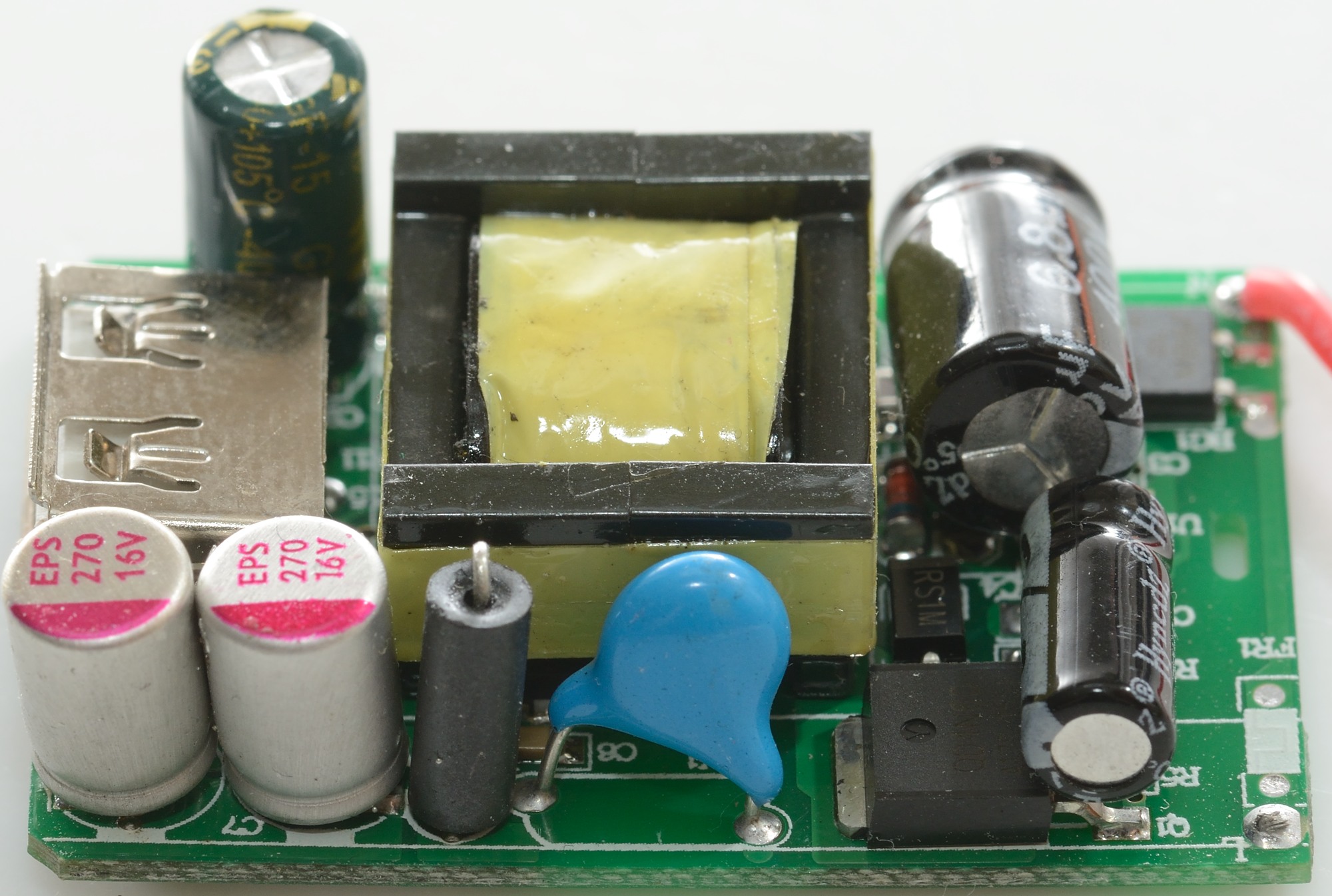
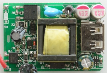
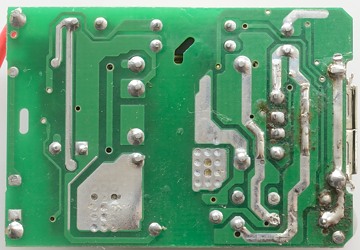
From this side the bridge rectifier, the opto coupler and the quick charge controller can be seen.
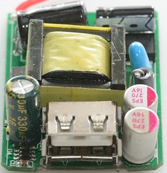
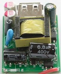
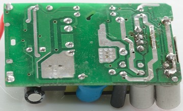
One the first picture the quick charge controller can again be seen beside the usb connector. The second picture has the mains switcher controller and the bridge rectifier.

On this side the blue safety capacitor is very obvious and the switcher transistor. There is also a ferrite bead, this works as a very small inductor and reduces noise.
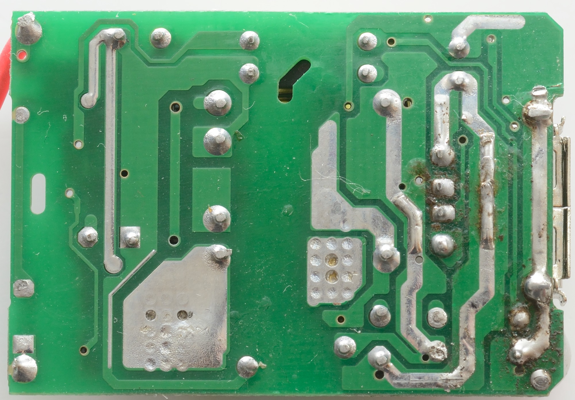
There is no parts on this side.
The area on the low volt side with lots of filled holes is the connection/heat sink for the rectifier diode.
The isolation distance is good enough, the problem is sparks that jumps from the transformer to the capacitors. A few extra turns of the yellow tape around the transformer core would probably have fixed it.
The charger passed the 2500 volt test, but failed the 5000 volt test, this makes it unfit for 230VAC mains voltage.
Conclusion
This is a very cheap QC2 charger, it works fairly well (Noise is a bit high). The design do probably not live up to EU standards due to the lack of filtering.
Even with the very attractive price I will not recommend the charge due to the failed high voltage test.
Notes
Index of all tested USB power supplies/chargers
Read more about how I test USB power supplies/charger