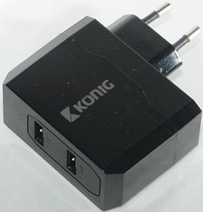
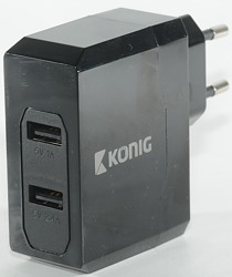
Konig 1A+2.4A CS34UW001BL
Official specifications:
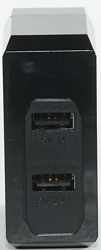
- No. of outputs: 2
- Usage: Home
- Socket type: USB
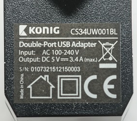
- Output voltage: 5 VDC
- Cable type: No Cable Included
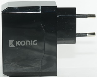
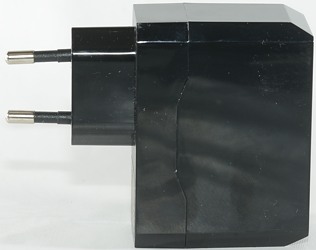
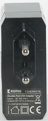
- Power plug: Euro / Type C (CEE 7/16)
- Colour: Black
- Voltage: AC 100 - 240 V
- Output current: 3.4 A
- Max output current per port: 1x 2.4A + 1x 1A
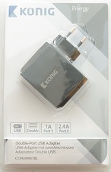
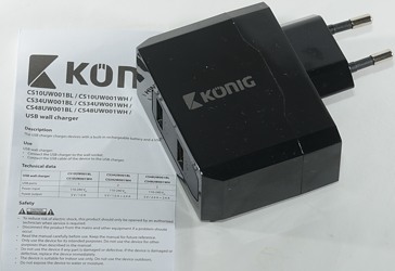
The box contains the charger and a multi language and multi device instruction/data sheet without any useful information.
Measurements
- Power consumption when idle is 0.25 watt
- 1A usb output is coded as usb charger (DCP)
- 2.4A usb outputs has automatic coding with Apple 2.4A as max.
- The two output ports are in parallel.
- Weight: 90.4g
- Size: 87 x 67 x 28.4mm
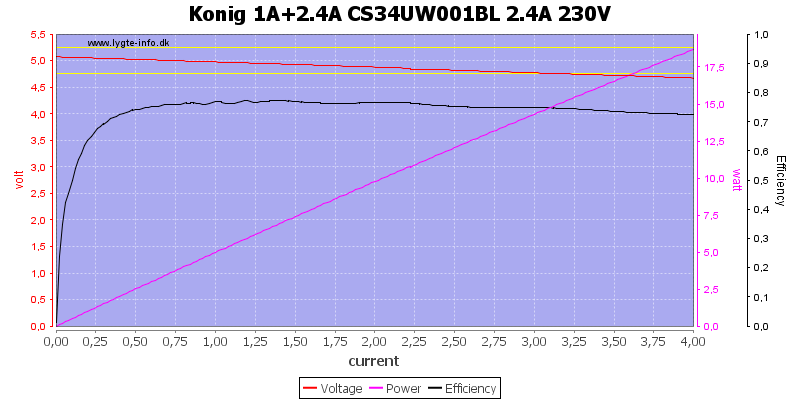
There is no individual overload protection on the 2.4A output
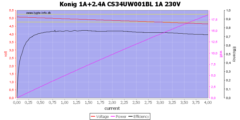
Same for the 1A output
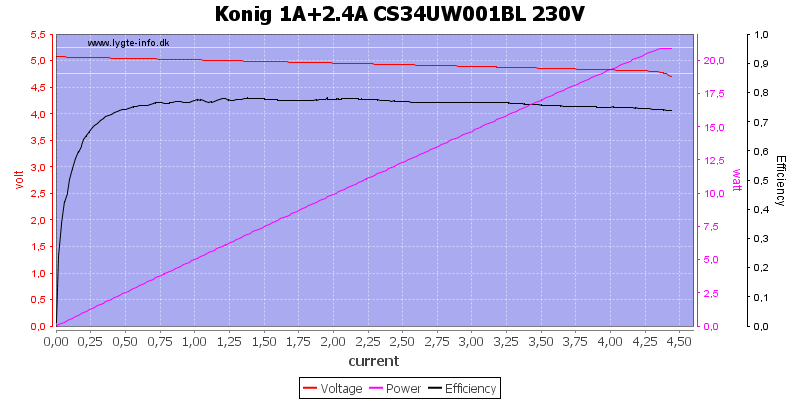
There is a total output limit at about 4.5A

The adapter runs fine on both 120VAC and 230VAC.
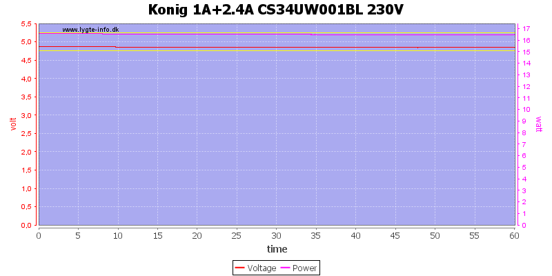
There is no problem delivering rated current for one hour.
The temperature photos below are taken between 30 minutes and 60 minutes into the one hour test.
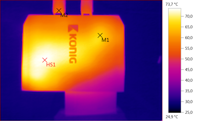
M1: 66,0°C, M2: 55,4°C, HS1: 73,7°C
HS1 is the transformer
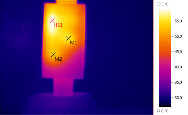
M1: 55,7°C, M2: 53,1°C, HS1: 59,3°C
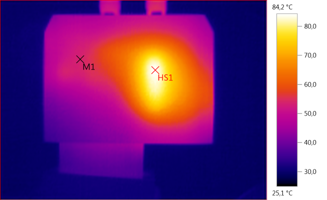
M1: 53,8°C, HS1: 84,2°C
Again HS1 is the transformer.
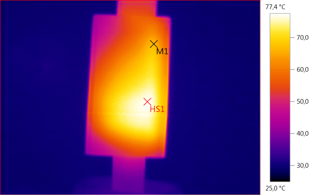
M1: 66,3°C, HS1: 77,4°C
HS1 is the rectifier diode here.
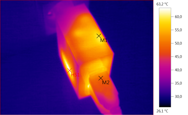
M1: 58,5°C, M2: 48,9°C, HS1: 63,2°C
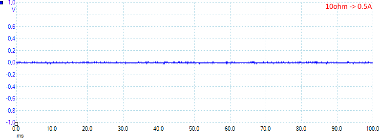
Noise at 0.5A load is: 5mV rms and 70mVpp.
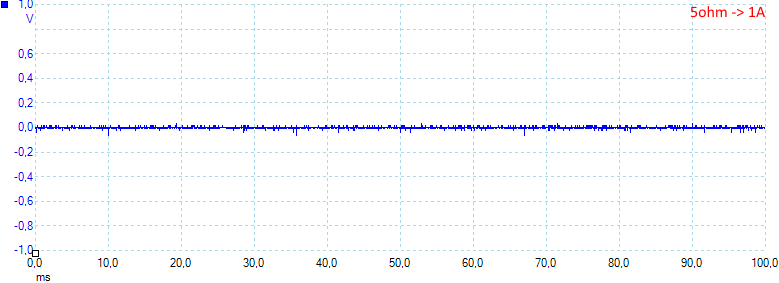
Noise at 1A load is: 5mV rms and 160mVpp.
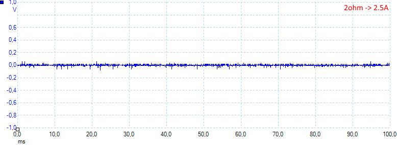
Noise at 2.5A load is: 9mV rms and 170mVpp.
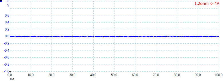
Noise at 4A load is: 8mV rms and 163mVpp.
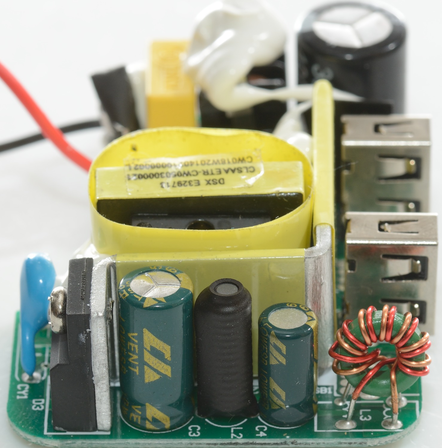
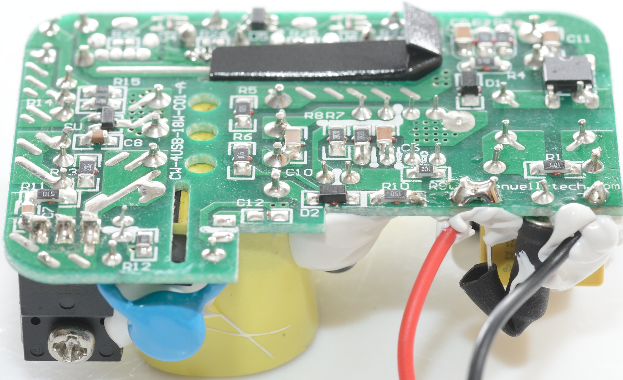
Tear down
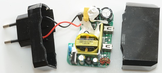
The charger looked easy to open: tie the bottom part in my vice and give the top part a few wacks with my mallet. It worked as expected.
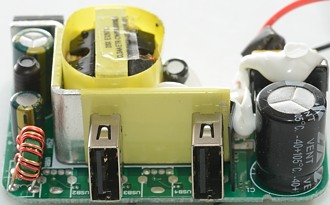
Some of the parts are hidden beneth the white stuff (It is there to keep parts fixed if the charger is dropped).
At the mains input is a fuse and a common mode coil. Part of the switcher IC can be seen beside the common mode coil.
Besides the mains transformer is an opto coupler and a safety capacitor (CY1).
The low volt side has a rectifier diode (D3) mounted on a large heatsink, an inductor between two capacitors and even a common mode coil on the output.
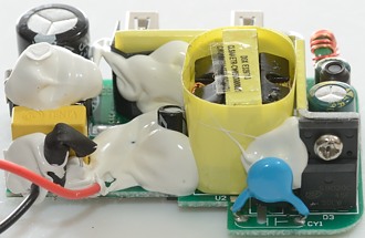
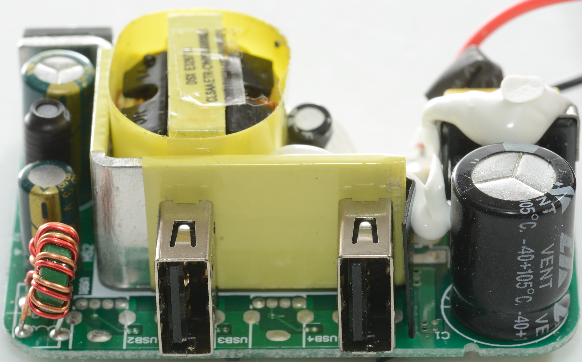
From this side the fuse, the safety capacitor and the rectifier diode can be seen.

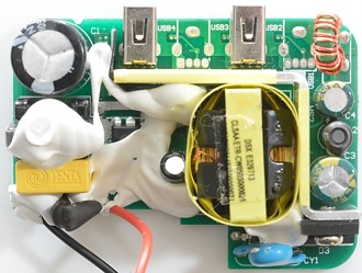
Here the two inductors L2 and common mode coil (L3) can be seen.
There is space for four usb outputs, but the total current is a bit weak for four outputs.

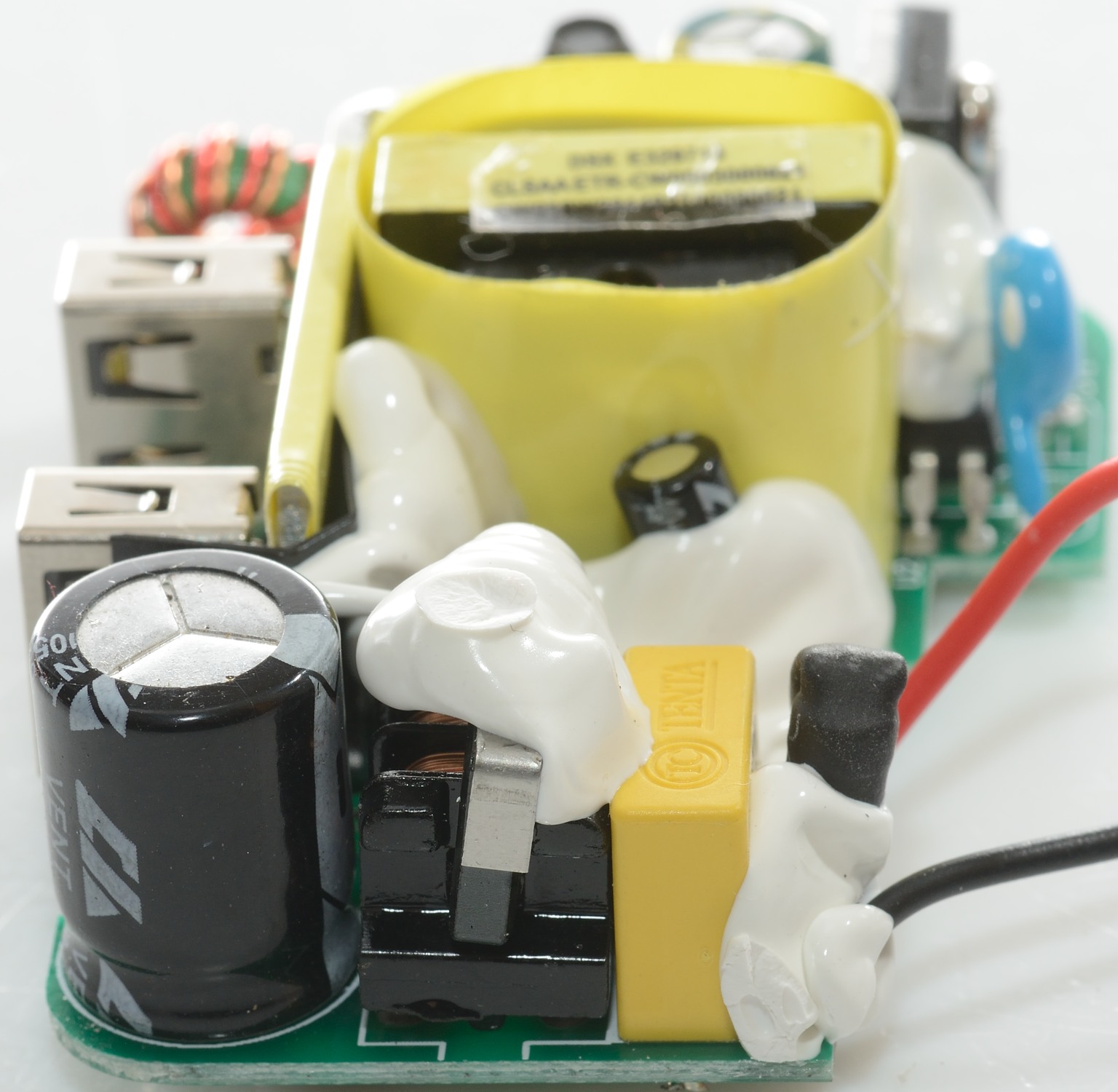
The common mode coil on the mains side can be seen here.
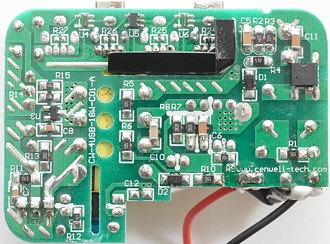
The bottom has a bridge rectifier at the mains input. The paper isolation between mains and low volt side can be seen in on of the slots in the circuit board.
The voltage reference is U3. There is one IC for automatic usb coding (U5).

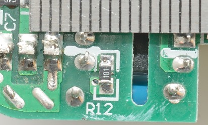
Due to the slot in the circuit board it only need 4mm safety distance and that is fulfilled.
Testing with 2830 volt and 4242 volt between mains and low volt side, did not show any safety problems.
Conclusion
The charger can supply the rated current without problems, has auto coding on the 2.4A port and DCP coding on the 1A port, is safe and has fairly low noise.
This makes it a good charger.
Notes
Charger was supplied by Pro backup (probackup.nl)
Index of all tested USB power supplies/chargers
Read more about how I test USB power supplies/charger
How does a usb charger work?