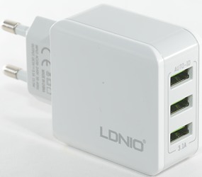
LDNIO 3 port ubs charger A3301
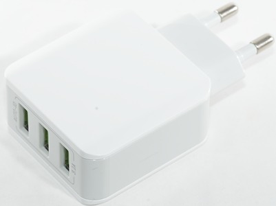
Official specifications:
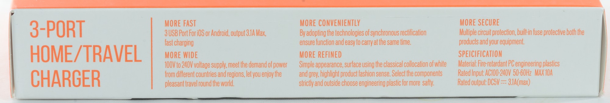
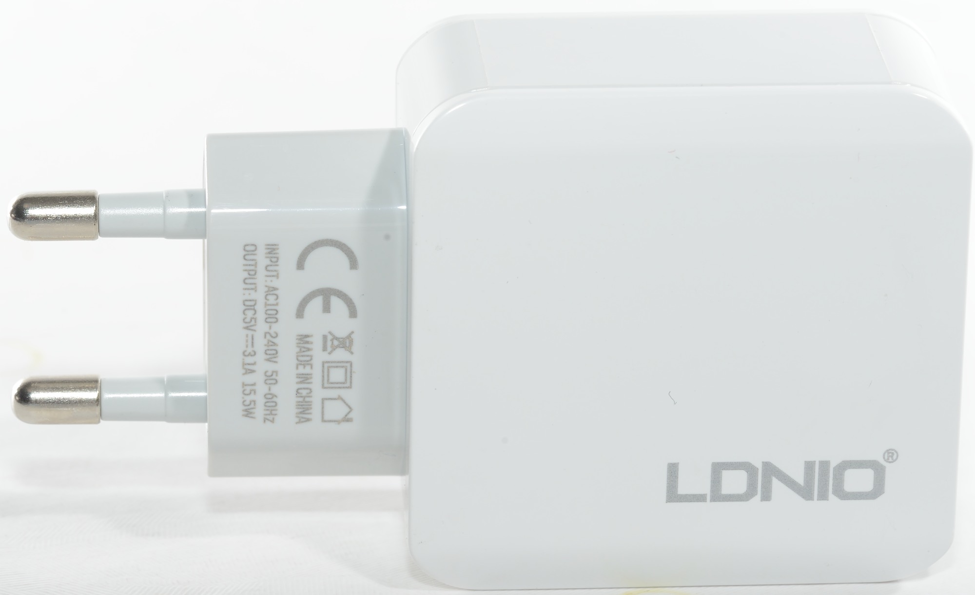
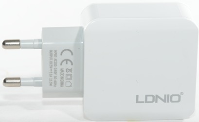
- Input:100-240V, 50-60Hz
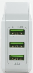
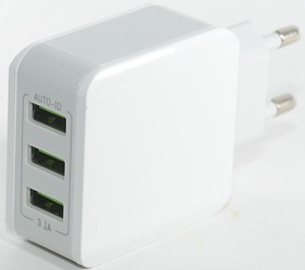
- Output: 5V/3.1A
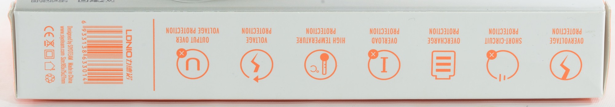
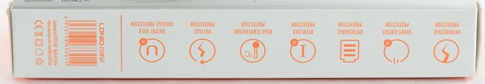
- Quick & short circuit / overtemperature / overvoltage / overcurrent protection;
I bought it from Aliexpress dealer Worthit Store
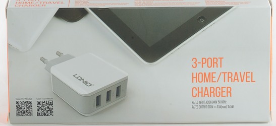
I got it in a card board box, it only contained the charger, no manual or usb cable.
Measurements
- Power consumption when idle is 0.23 watt
- Both usb output are auto coding with Apple 2.4A as max.
- Outputs are in parallel.
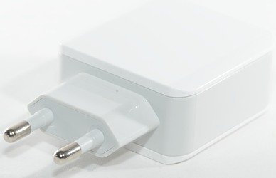
- Weight: 63.7g
- Size: 88.6 x 50.0 x 25.5mm

Each port is rated at 2.4A according to coding, but this port easily deliver 5A, this means no individual overload protections on the ports.
Same with this one.
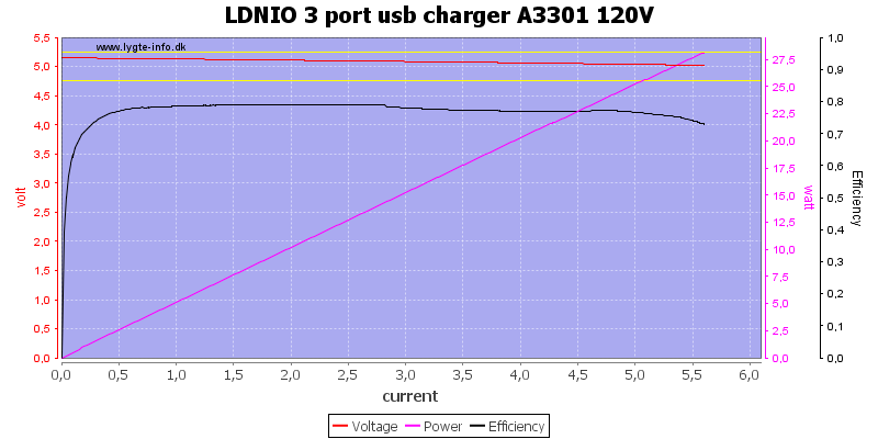
The charger works fine on 120VAC, delivering up to 5.6A
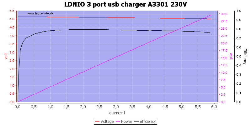
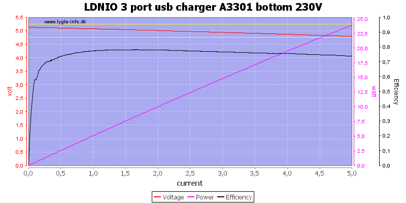
On 230VAC it can deliver slightly more.
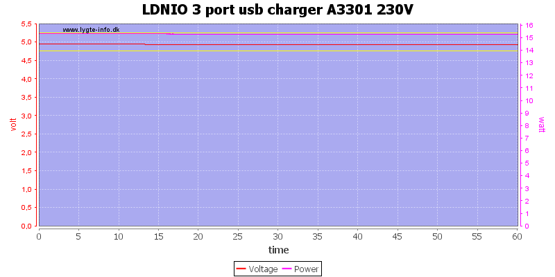
No problems running one hour at 3.1A.
The temperature photos below are taken between 30 minutes and 60 minutes into the one hour test.
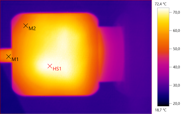
M1: 57,3°C, M2: 56,1°C, HS1: 72,4°C
HS1 is the rectifier.
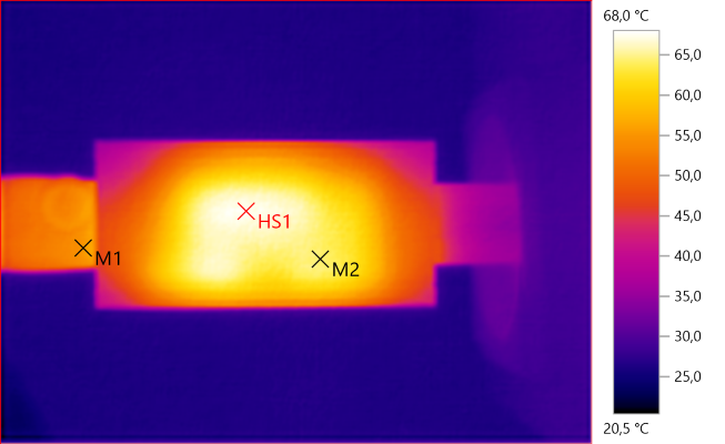
M1: 55,4°C, M2: 64,4°C, HS1: 68,0°C
HS1 is the transformer.
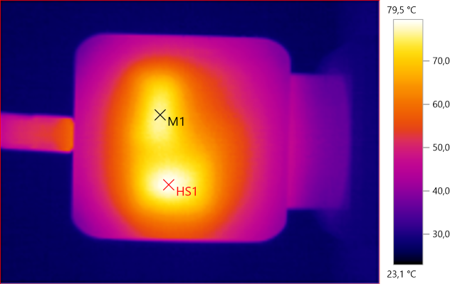
M1: 76,6°C, HS1: 79,5°C
HS1 is the transformer and M1 is the rectifier.
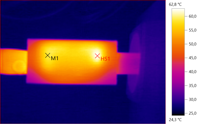
M1: 58,6°C, HS1: 62,8°C
HS1 must be heat from the switcher ic.
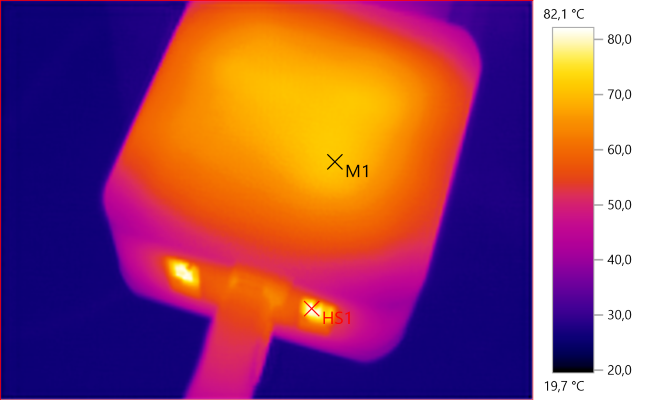
M1: 71,2°C, HS1: 82,1°C
HS1 is heat from the transformer.
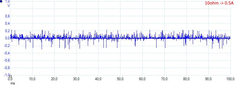
At 0.5A the noise is 28mV rms and 634mVpp.
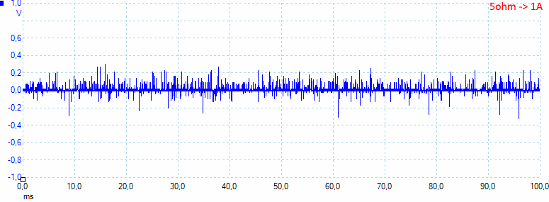
At 1A the noise is 32mV rms and 701mVpp.
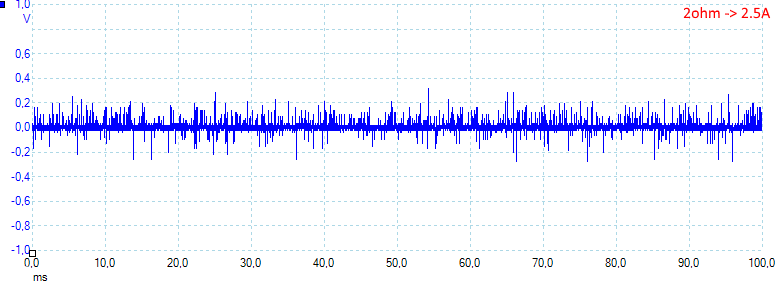
At 2.5A the noise is 39mV rms and 637mVpp, this is rather high.
Tear down
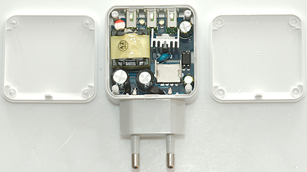
Some pressure from my vice and the two lids popped open (A spudger may have done it).
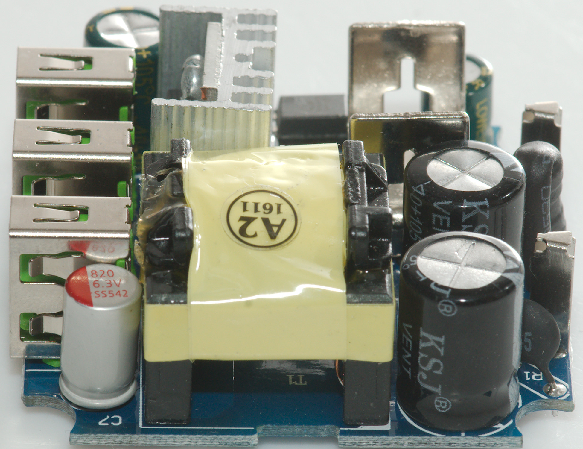
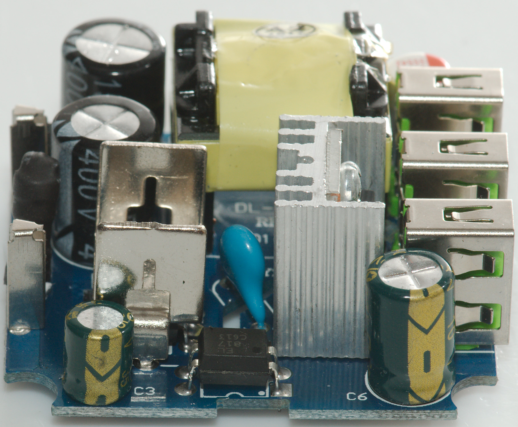
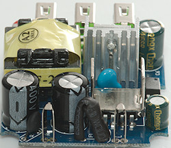
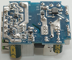
At the mains connection is a fuse wrapped in heat shrink and a inrush current limiter. The switcher ic is hidden under a heatsink and just beside it is the opto feedback and the blue safety capacitor.
The rectifier is mounted on a heatsink and between the usb connectors is two leds.

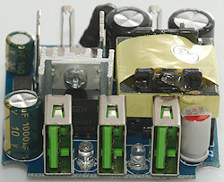
On the first image the inrush current limiter can be halfway seen (Marked R1 on the circuit board).
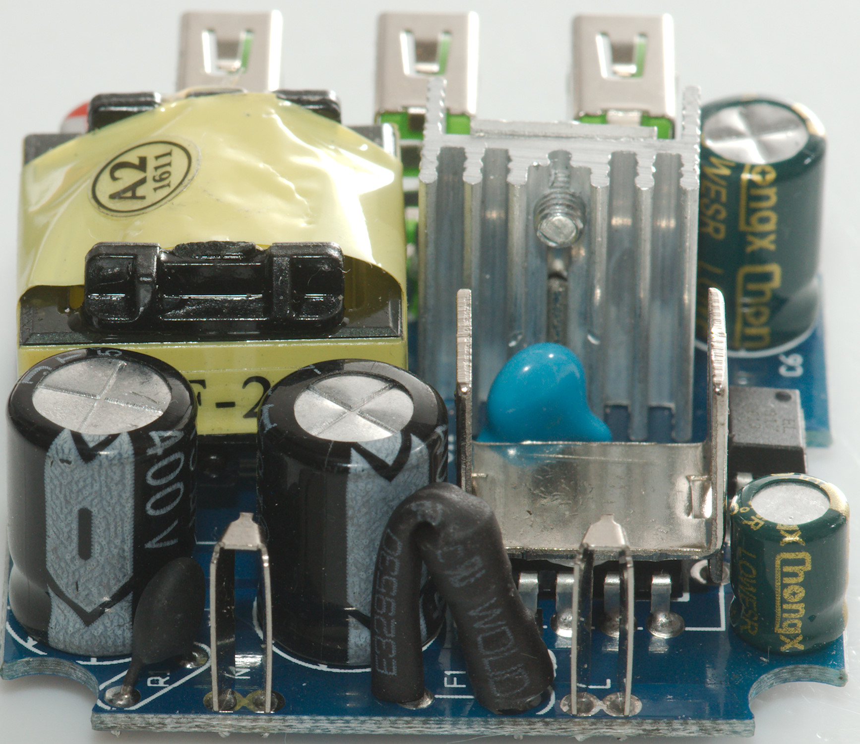
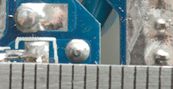
The second picture shows the two leds and the rectifier diode behind the usb connectors.
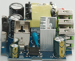
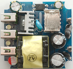
On the first picture the optocoupler can be seen with the blue safety capacitor between the heat sinks. A corner of the switcher ic can be seen beneath the left heatsink.
On the second picture the fuse is in center (Marked F1 on the circuit board).
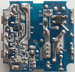
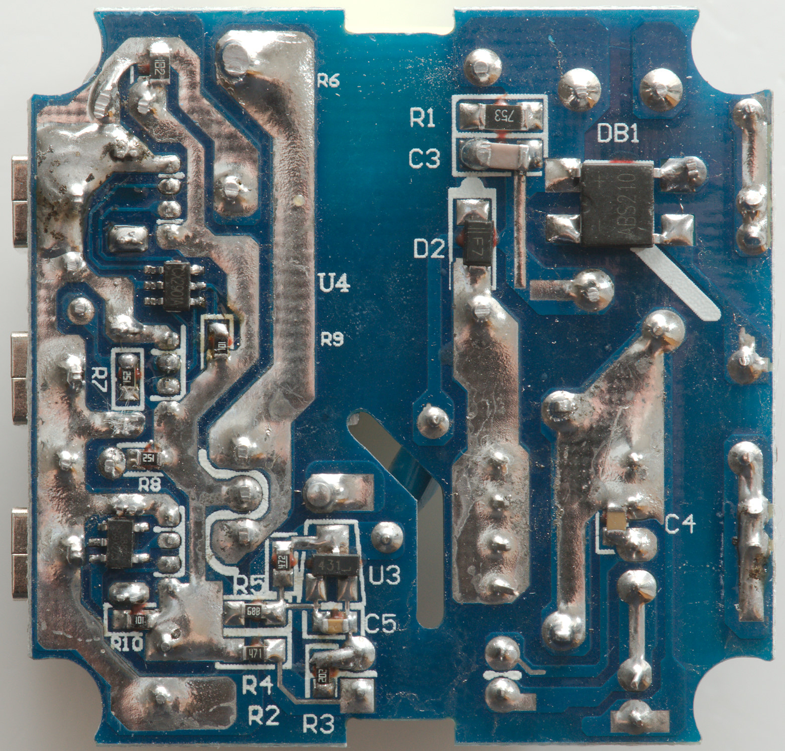
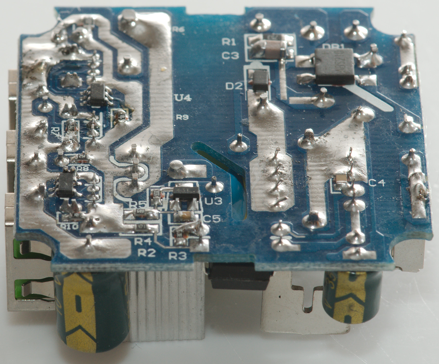
On this side is the bridge rectifier (DB1), the two auto coding chips (U4:CX2901 dual channel and MA5887 single channel) and a 431 reference (U3).
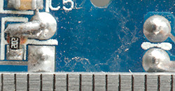
Safety distance across the slow is a bit low (It is supposed to be 4mm).
Testing with 2830 volt and 4242 volt between mains and low volt side, did not show any safety problems.
Conclusion
The auto coding is a good detail, but with 3 outputs the 3.1A is a rather low current, I could also have wished for less noise. The slightly low safety distance do also mean it is not completely safe to use at 230VAC
Notes
Index of all tested USB power supplies/chargers
Read more about how I test USB power supplies/charger
How does a usb charger work?