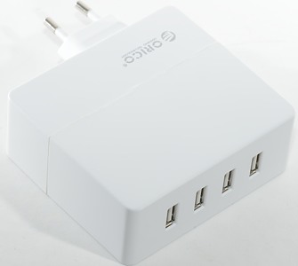
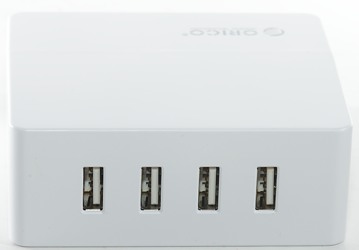
Orico 4-Port Wall USB charger DCA-4U
Official specifications:
- Compatible Brand: HTC,Apple iPhones,Samsung,Motorola,Toshiba,Panasonic,Blackberry,Nokia,Sony-Ericsson,LG,Palm
- Type: Travel
- Brand Name: ORICO
- Power Source: A.C. Source,USB
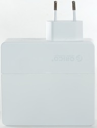
- Socket Type: For E.U.
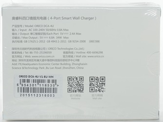
- Model Number: ORICO DCA-4U-EU-WH
- Item: 4 Port USB Wall EU Charger
- Color: Black/White
- Product Size: 90*85*35mm
- N.W/G.W: 175g/290g
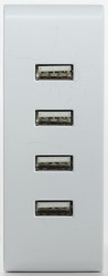
- Interface: 5V2.4A*4
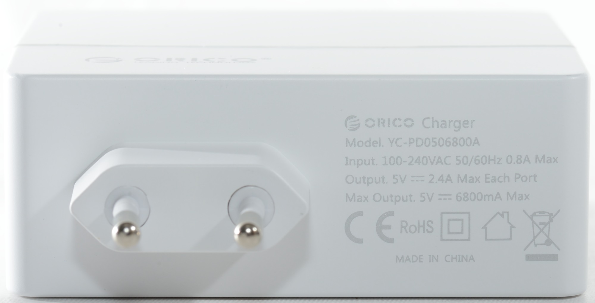
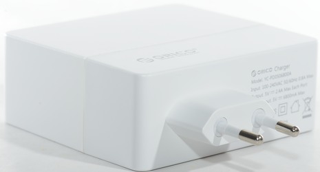
- AC Input: 100-240VAC/0.8A/50-60Hz
- Output: 5V6A30W
- Advantage: Over-heated/Over-current/Over-charging protection
- Certificate: CE/ROHS
- Plug: Original EU Plug
I got it from aliexpress dealer Orico Technologies Co., Ltd.
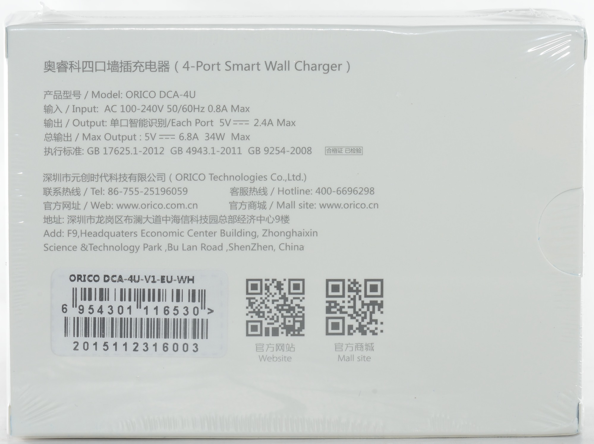
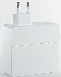
I got this charger in a cardboard retail box.
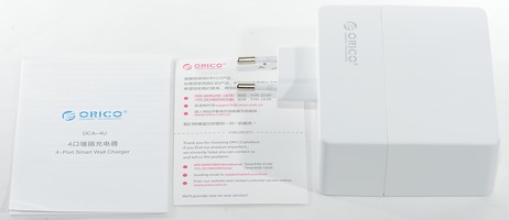
The box contained the charger, a instruction sheet and a thank you note with Orico phone numbers.
Measurements
- Power consumption when idle is 0.14 watt
- All usb outputs is auto coding with Apple 2.5A as maximum.
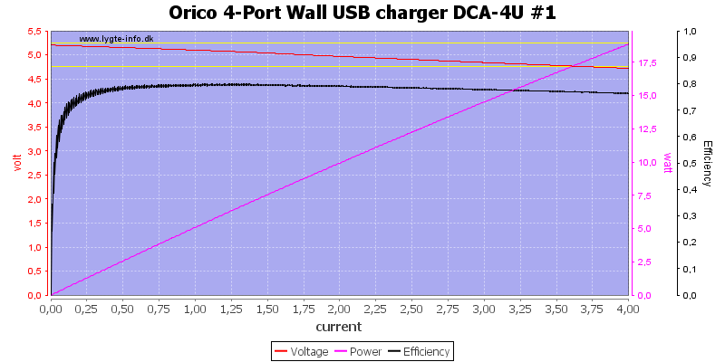
There is no individual overload protection on the ports.
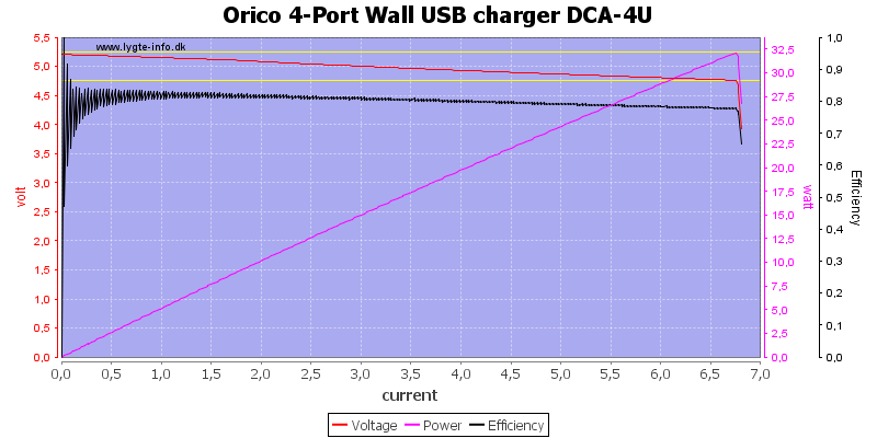
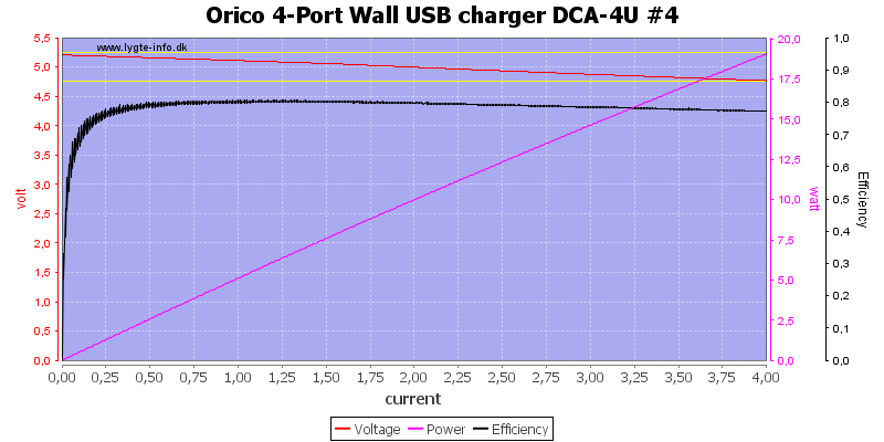
Running all outputs in parallel I found the overload protection at about 6.8A, exactly the value specified on the charger.
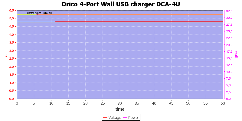
A one hour test with 6.5A load was no problem.
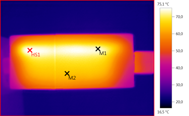
The temperature photos below are taken between 30 minutes and 60 minutes into the one hour test.
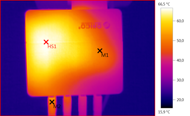
M1: 49,9, M2: 50,4, HS1: 66,5
HS1 is the transformer.
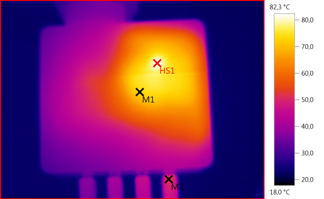
M1: 72,5, M2: 51,5, HS1: 82,3
HS1 is again the transformer.
M1: 73,0, M2: 64,9, HS1: 75,1
The hot line must be the slot for the circuit board, this improves the heat transfer.
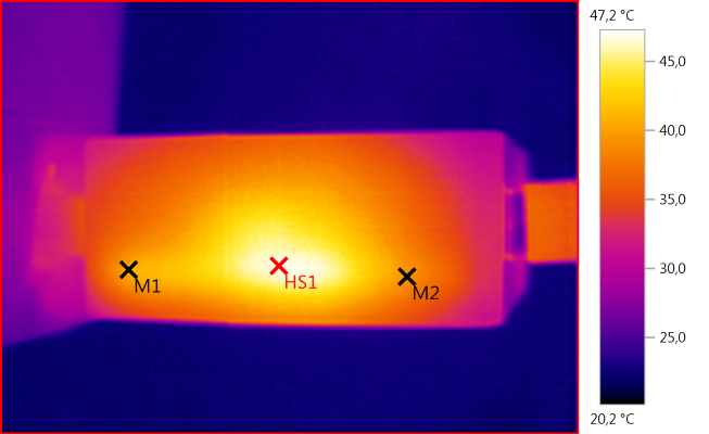
M1: 40,4, M2: 39,1, HS1: 47,2
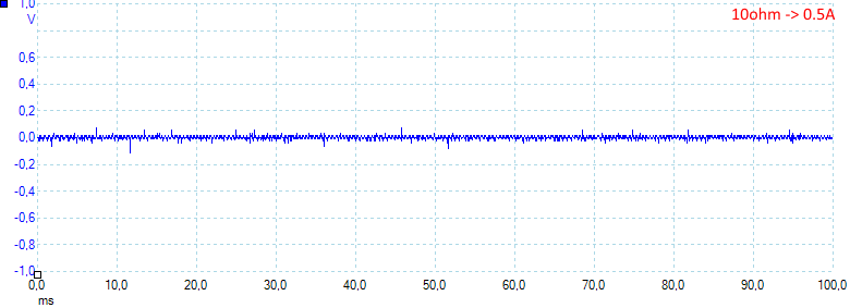
The noise is low at 10mV rms and 170mVpp
Increasing the load do not increase the noise: 6mV rms and 170mVpp
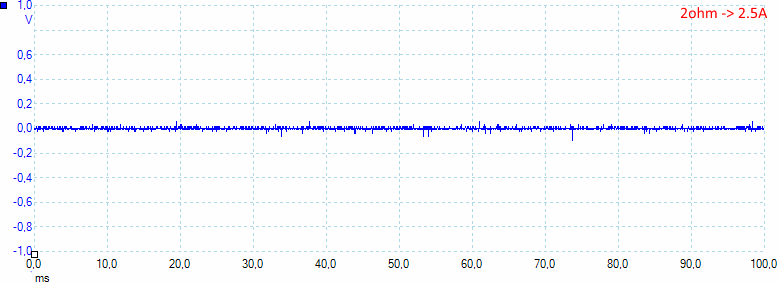
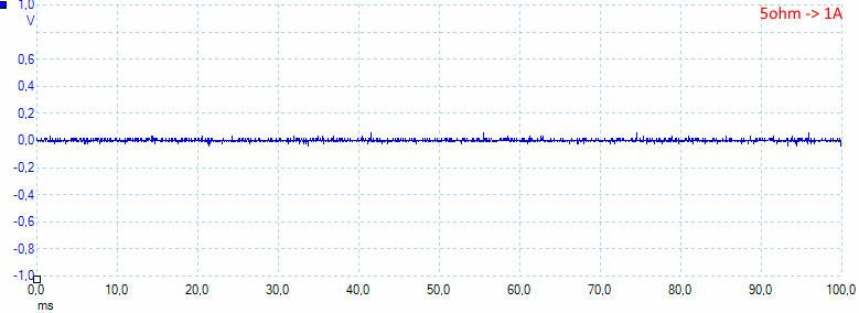
Even at 2.5A the noise is about the same: 7mV rms and 150mVpp
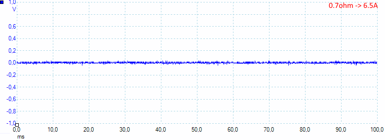
When running all ports together at full load the noise very low: 7mV rms and 81mVpp
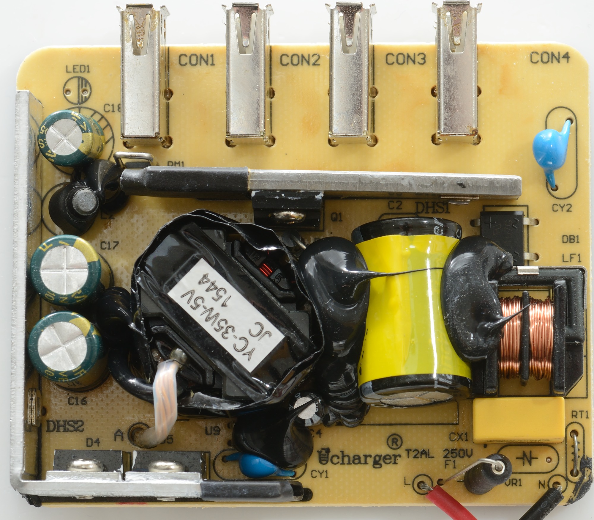
Tear down
I mounted it in my vice and hit it a few times with the mallet to open it.

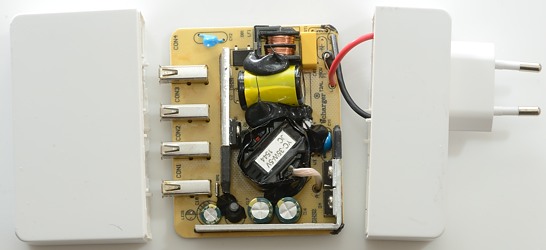
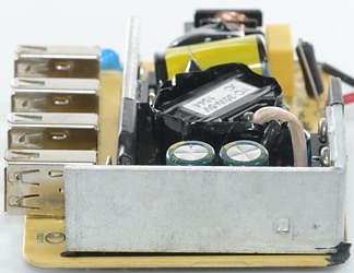
At the mains input there is a fuse, then a commmon mode coil (LF1) and a bridge rectifier (DB1). The mains switcher transisotr (Q1) is mounted on the heatsink behind the usb connectors.
Below the black stuff the opto coupler is hidden (U9), there is two safety capacitors (CY1, CY2).
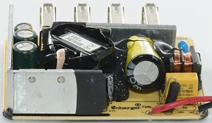
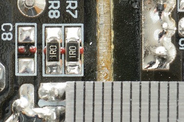
On the other heatsink the two rectifier diodes are mounted (D4, D5), there is also a filter inductor (L2, between C17 and C18). For measuring the current a wire resistor is used (RM1).
All the black stuff is used to secure the parts stay where they are supposed to be, even if the charger is dropped, but I would have like some to secure the heatsink (DHS1) behind the usb connectors.
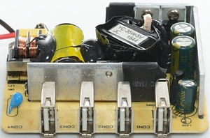
Behind con1 a little bit of the current measuring resistor can be seen (It is just a wire).
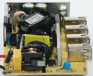
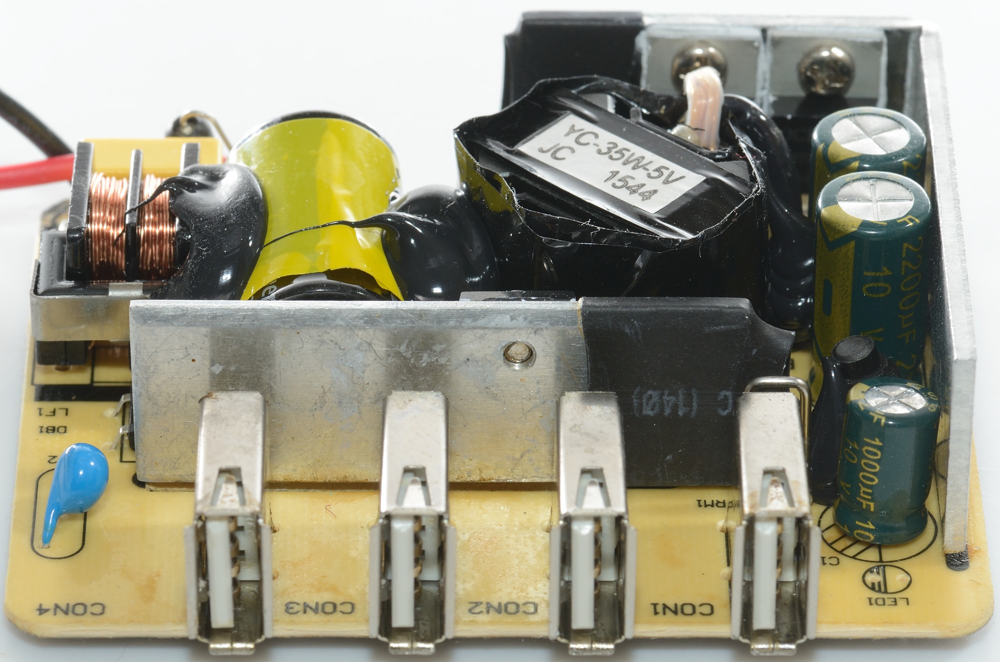
The black round part at the red wire is the fuse. The yellow capacitor is marked X2, this means it can be used accross mains voltage.
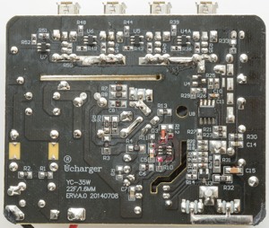
Here is the switcher controler (U1), the over current (U8 LM358), the voltage control (U3 CYT431A) and the four usb auto coding chips (U4A, U5, U6, U7 NS3601)
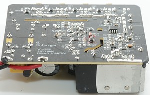
The isolation distance is enough if the heatsink do not touch the circuit board.
Testing with 2500 volt and 5000 volt between mains and low volt side, did not show any safety problems.
Conclusion
This usb power supply looks good, it has low noise, it can deliver lots of current and has auto coding and the safety is acceptable.
Notes
Index of all tested USB power supplies/chargers
Read more about how I test USB power supplies/charger