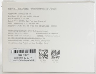
Orico 5 port usb charger CSE-5U
Official specifications:
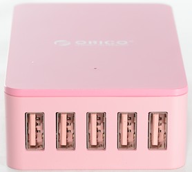
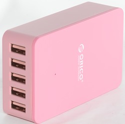
- Port: 5 USB Charging Ports
- Rated Power: 40W
- Output Per PortIntelligent Identification: 5V 2.4A
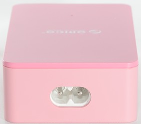
- Input Voltage: 100-240V AC
- ControllerIntelligent Detective IC
- Dimension: 100 x 60 x 28mm
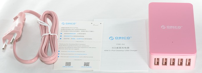
The box contained the charger, mains cable, instruction sheet and a warranty card.
Measurements
- Power consumption when idle is 0.1 watt.
- Usb output is automatic coding with Apple 2.4A as max.
- There is a white led behind the small hole on top of the charger.
- When a output shuts down it will not affect the other channels.
- Overloaded outputs will recover automatic when load is removed.
- Ground is common, overload disconnects +5V
- Weight without any accessories or mains cable is 152 grams.
- Size is 100x60x27.9mm
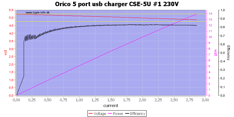
The ports has individual port protection, here it trips at about 2.8A
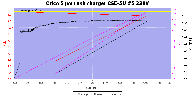
There is some tolerance on the protection, on this port is trips at 2.5A, this is good enough for a 2.4A port.
With this variation between the two ports, I also checked the 3 other ports, they were between 2.6A and 2.8A.
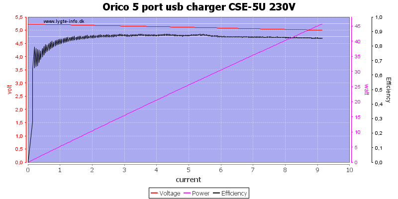
The total current limit is between 9A and 10A. The charger has very good efficiency.
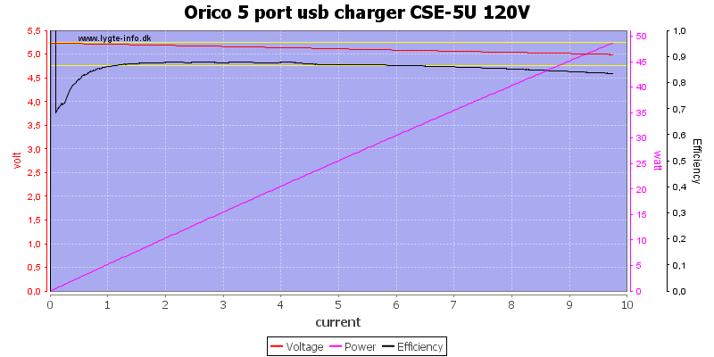
At 120V it is closer to 10A.
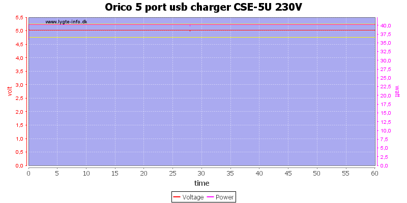
Running at 8A output for one hour was not a problem.
The temperature photos below are taken between 30 minutes and 60 minutes into the one hour test.
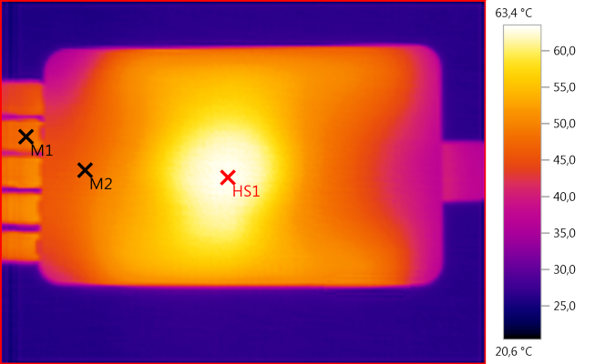
M1: 48,1°C, M2: 47,2°C, HS1: 63,4°C
HS1 is the transformer.
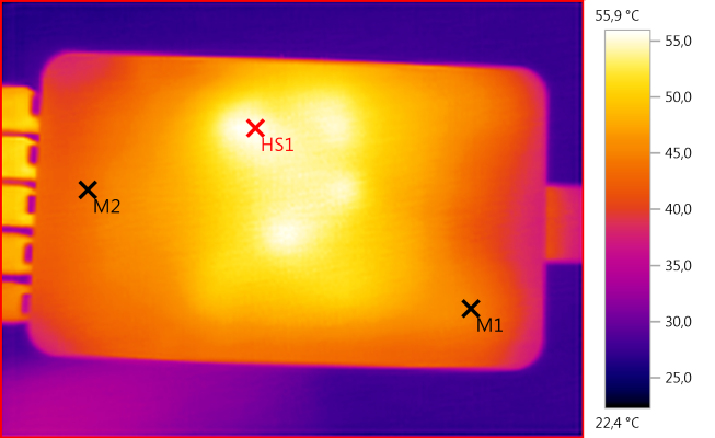
M1: 44,9°C, M2: 43,6°C, HS1: 55,9°C
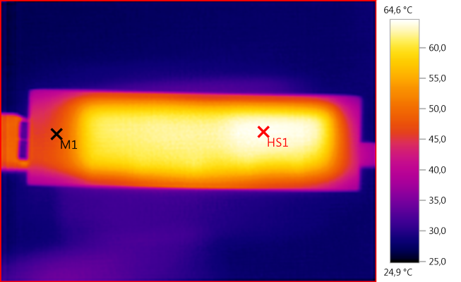
M1: 47,6°C, HS1: 64,6°C
I wonder why the end is hotter than the middle, the transistor is at the middle. Maybe it is because the heatshrink touched the box at the end?
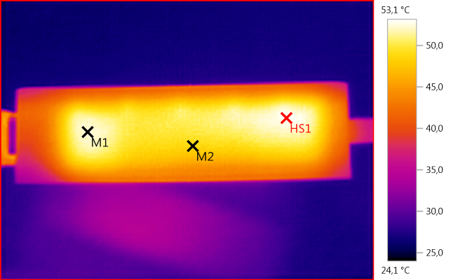
M1: 52,5°C, M2: 48,9°C, HS1: 53,1°C
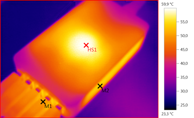
M1: 50,2°C, M2: 53,3°C, HS1: 59,9°C
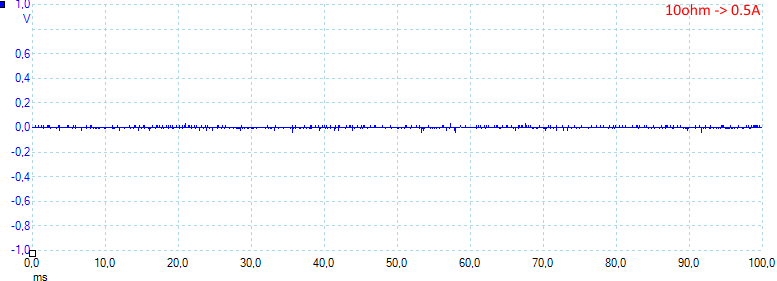
Noise at 0.5A load is: 5mV rms and 115mVpp.
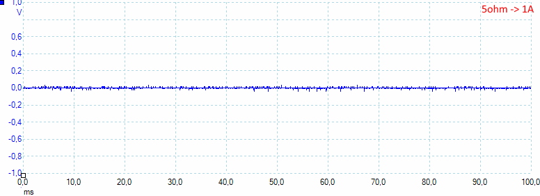
Noise at 1A load is: 6mV rms and 110mVpp.
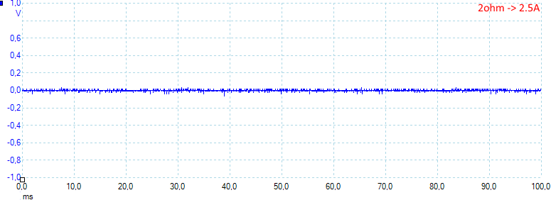
Noise at 2.5A load is: 6mV rms and 102mVpp.
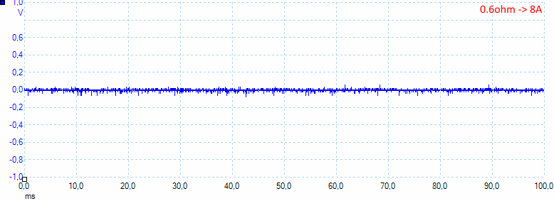
Noise at full load is: 12mV rms and 184mVpp.
Tear down
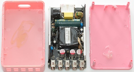
Some pressure with my vice and I could break the lid off.
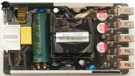
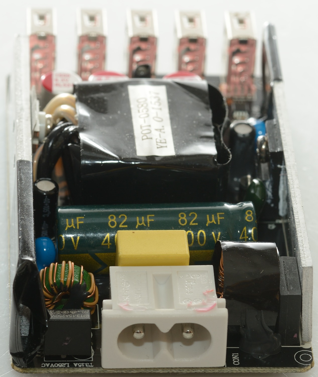
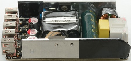
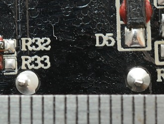
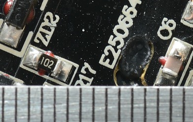
Just after the mains connector is the fuse, then two common mode coils with a capacitor between and after them a bridge rectifier (BD1). The two heatsinks has the mains switcher transistor (Q1) and the rectifier transistor (Mounted with a isolation pad). There is two blue safety capacitors. The led (LED1) is packed in black heatshrink. Behind the usb connectors are the chips (U5, U6, U7, U8, U9: marked 2500) that handles both auto coding and current limit.
It might not be very visible, but both coils, the transformer and the capacitor is glued to the circuit board. This is good, then they will not move if the charger is dropped.
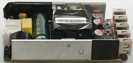
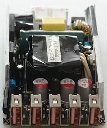
The silpad isolating the rectifier transistor from the heatsink is visible here.

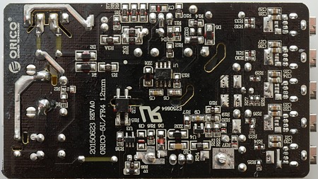
There are a few interesting parts on this side: The mains switcher (U1: NF11180), the opto coupler (U2:EL357N), the synchronous rectifier controller (U3: Marked 19HFH), the reference (U4: 431).
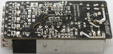
There is very good isolation distance on the circuit board, anything that is a bit close has a isolation slot.
With the isolation slot only 4mm is required, the glue in the slot spoils it a bit, but even if it had filled the slot exactly, there would still be 6mm.
Testing with 2830 volt and 4242 volt between mains and low volt side, did not show any safety problems.
Conclusion
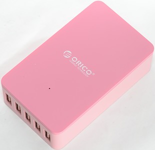
There is some consequence in the use of the pink color: charger including usb connectors and mains cable (For people not liking pink it also exist in black).
I am impressed with this charger: Lots of current for 5 ports, auto coding, individual port protection, very low noise, good safety.
This is a very good usb charger / power supply.
Notes
My high voltage test is done with a real HiPot tester allowing me to use the correct voltages for US and EU.
Index of all tested USB power supplies/chargers
Read more about how I test USB power supplies/charger