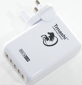
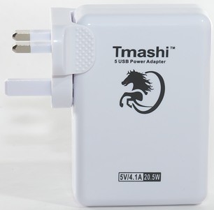
Tmashi 5 port 4A
Official specifications:
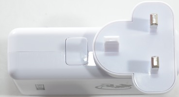
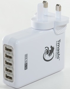
- AC wall charger with 5USB ports Plug US,EU,UK and SAA for choose
- Supports charging 5 devices simultaneously through just one wall socket.
- Designed with blue LED indicators.
- Glossy design prevents scratches
- Solid and sturdy shell prevents break or cracks
- High-class click-spring design prevents AC pins from slipping out
- Built-in IC smart fuse with double protection to check on overheat, overcurrent, overload and short circuit
- High efficiency and low energy consumption.
- Compact, lightweight, portable and very easy to operate.
- Ideal for indoor use only.
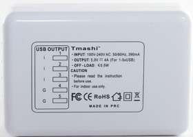
- Input: 100-240V AC, 50/60Hz
- Output: 5V--4.1A /20.5w (For 1-5*USB)((1-3 port for Apple iPad; 4-5 port for Samsung Galaxy tabs & smartphones; all FIVE are also applicable on iPhone/samsung/htc phones or other USB-charged electronics
- Plugs: EU,US,UK,SAA for choose
- Color:White
I do not know where I got it, but it can found at Ebay dealer: tmashi-store

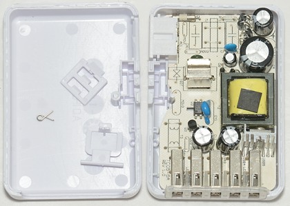
I got this charger in a plastic bag.
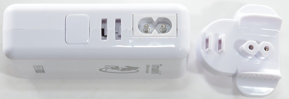
The power plug is seperate from the charger and it is possible to order it with different plugs, but not with all plugs for travel usage.
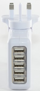
There is a blue led between port 1&2 and 4&5.
Measurements
- Power consumption when unloaded: 0.25 Watt
- Usb output is codes as Apple 2.1A and Samsung tablet
- All usb outputs are in parallel.
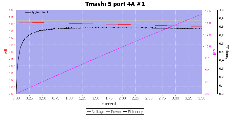
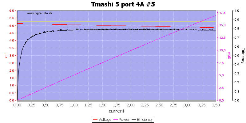
There is not much different between usb port #1 and #5, except #5 is slightly higher in voltage.
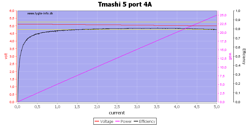
Running all outputs in parallel up to 5A works fine, but I would have liked a overload protection kicking in (I did a fast test up to 8A without seeing any protection).
No problem running at 4A for one hour.
The temperature photos below are taken between 30 minutes and 60 minutes into the one hour test.
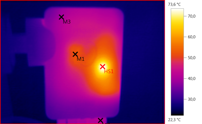
M1: 51,6°C, M2: 41,0°C, M3: 40,0°C, HS1: 73,6°C
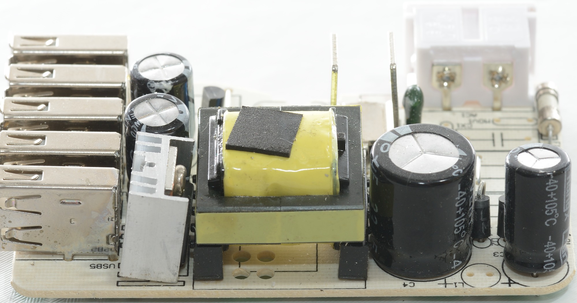
HS1 is probably the transformer and the temperature is acceptable for a transformer.
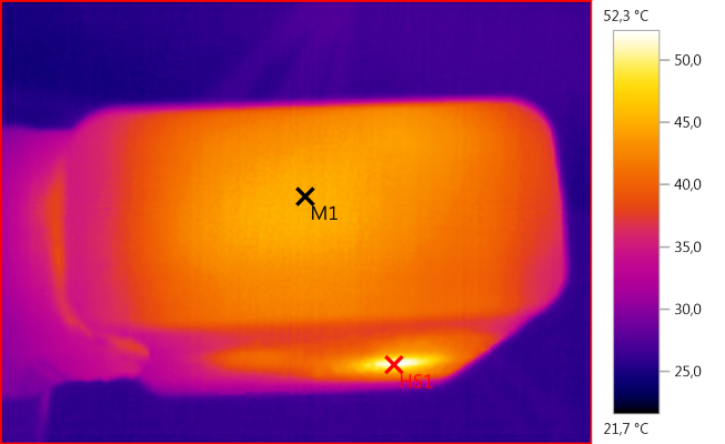
M1: 45,2°C, HS1: 52,3°C
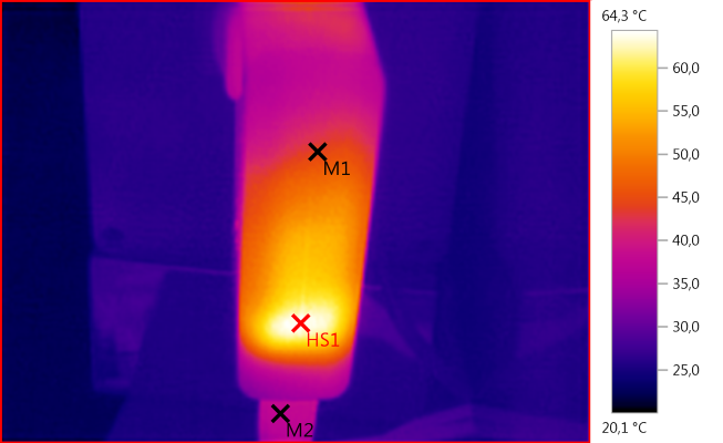
M1: 44,1°C, M2: 37,7°C, HS1: 64,3°C
HS1 must be the rectifier diode.
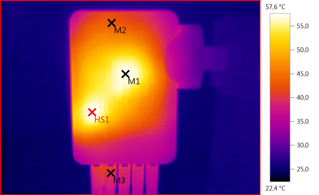
M1: 57,1°C, M2: 43,2°C, M3: 40,2°C, HS1: 57,6°C
M1 must be the mains switcher and HS1 must be the rectifier diode.
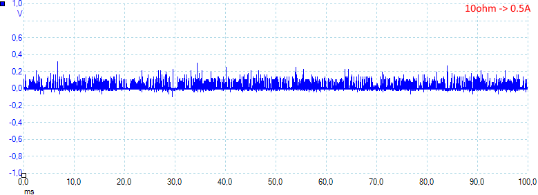
At 0.5A the noise is 38mV rms and 550mVpp. The rms noise is fairly low, but there is some spikes that gives a high peak noise.
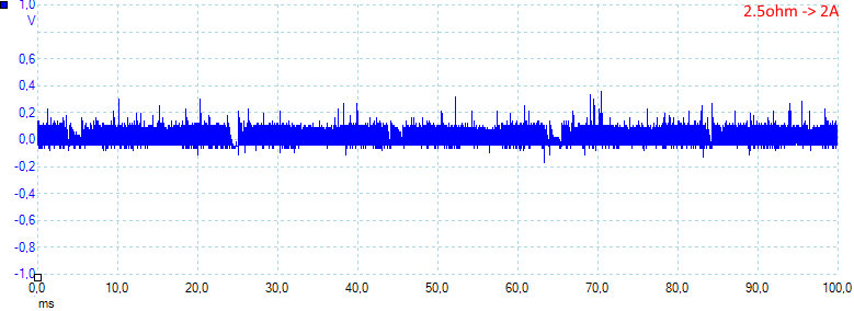
At 2A the noise is 62mV rms and 570mVpp
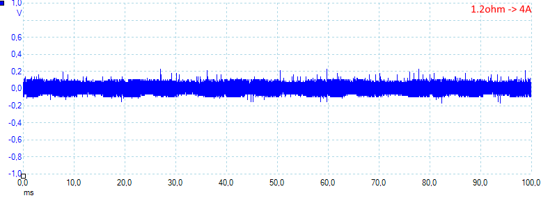
At 4A the noise is 69mV rms and 510mVpp
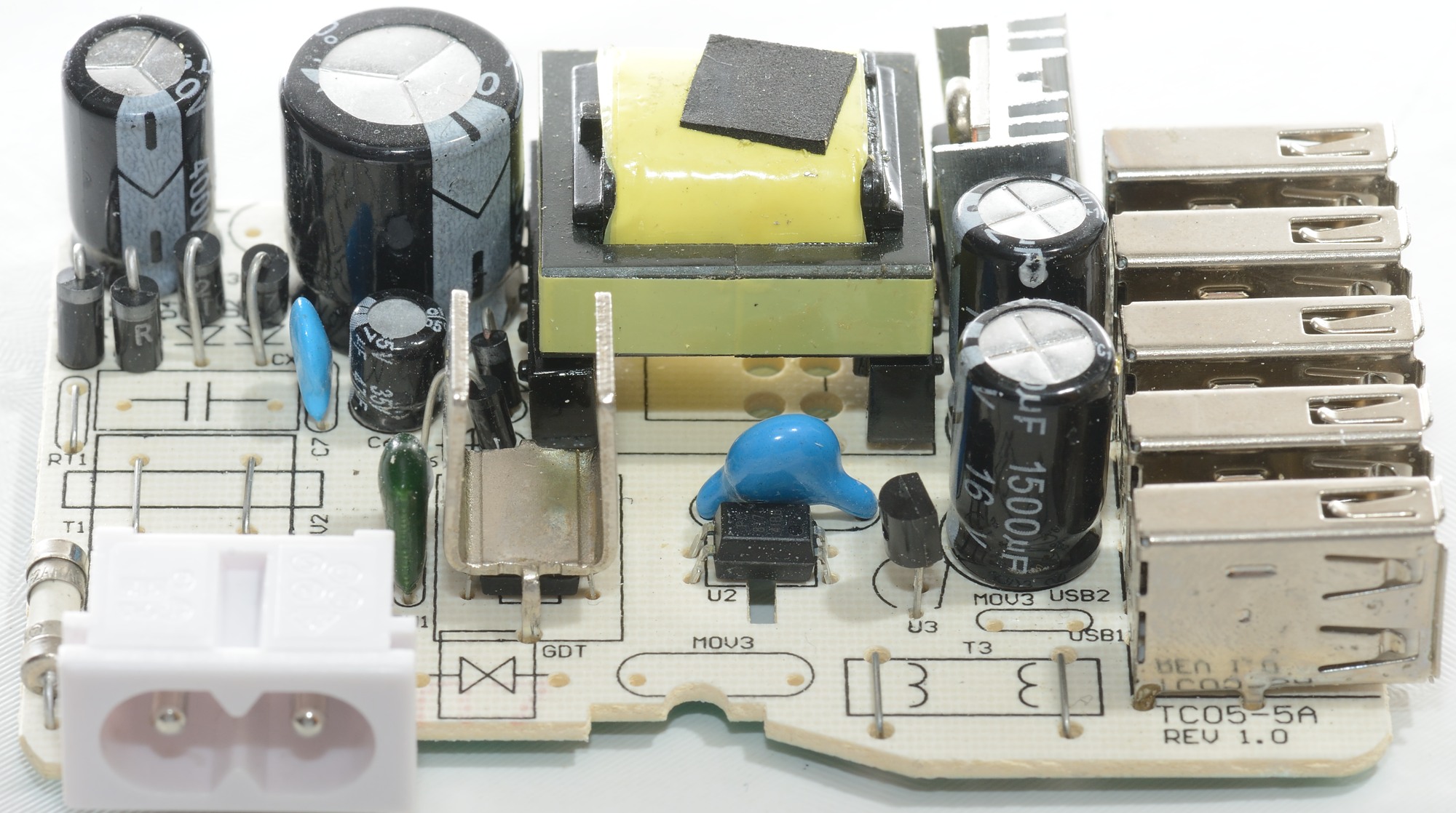
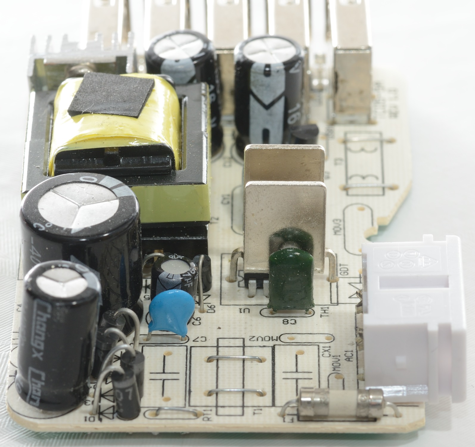
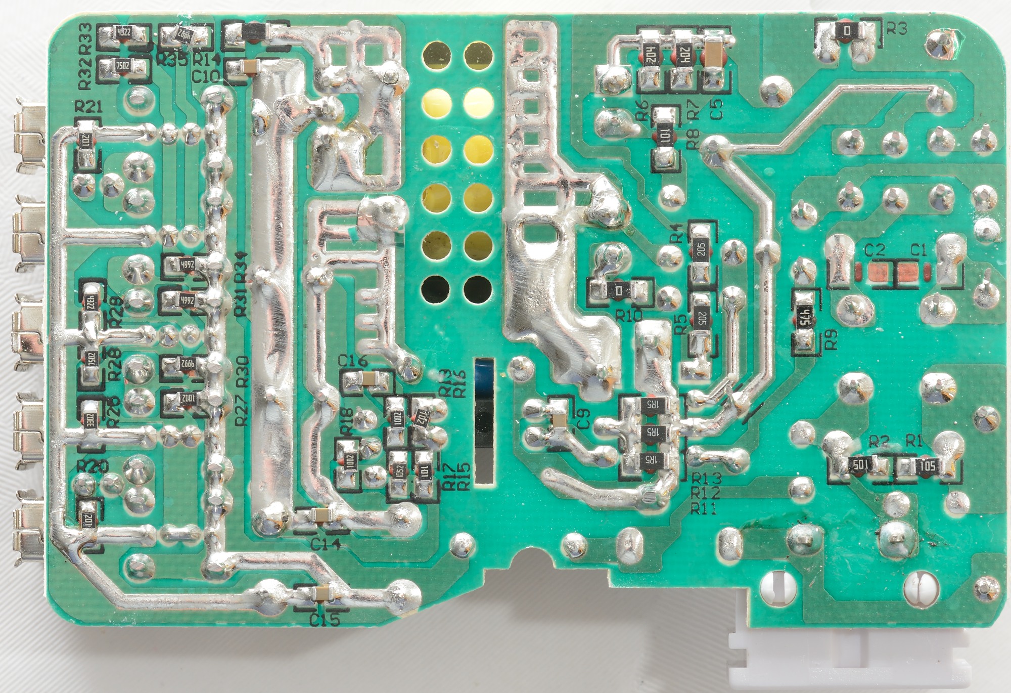
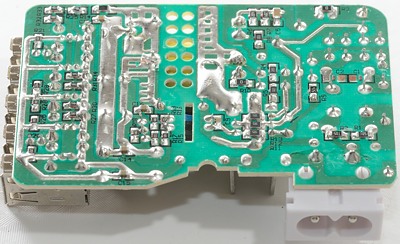
Tear down
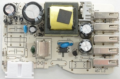
It looks like a lot of parts has been removed from the design. Most of the missing parts are designed to reduce EMC and make it less sensitive for spikes on the main.
The MOV3 part is not legal to mount, it would directly transfer spikes from the mains to the low volt side.
The input side has a fuse, bridge rectifier (4 diodes), capacitor and a switcher IC (Below a heatsink).


Between the usb connectors is is possible to see the leds.

The power starts at usb port #5 and usp port #1 has the longest traces on the circuit board, that is the reason for the small performance difference between them.
Note: The port numbers I am using is the ones on the box, not the ones on the circuit board that are reversed.
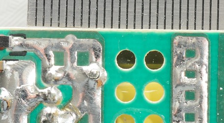
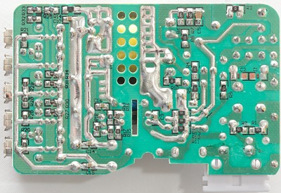
There is no issues with the isolation distance, it is fine.
Testing with 2500 volt and 5000 volt between mains and low volt side, did not show any safety problems.
Conclusion
This charger might have been a fairly good charger, before all the parts where removed from the design, without these parts I doubt it will pass the EMC part of the CE test.
The safety looks good, except the missing overload protection, both for each usb port and for the full device.
Notes
Read more about how I test USB power supplies/charger