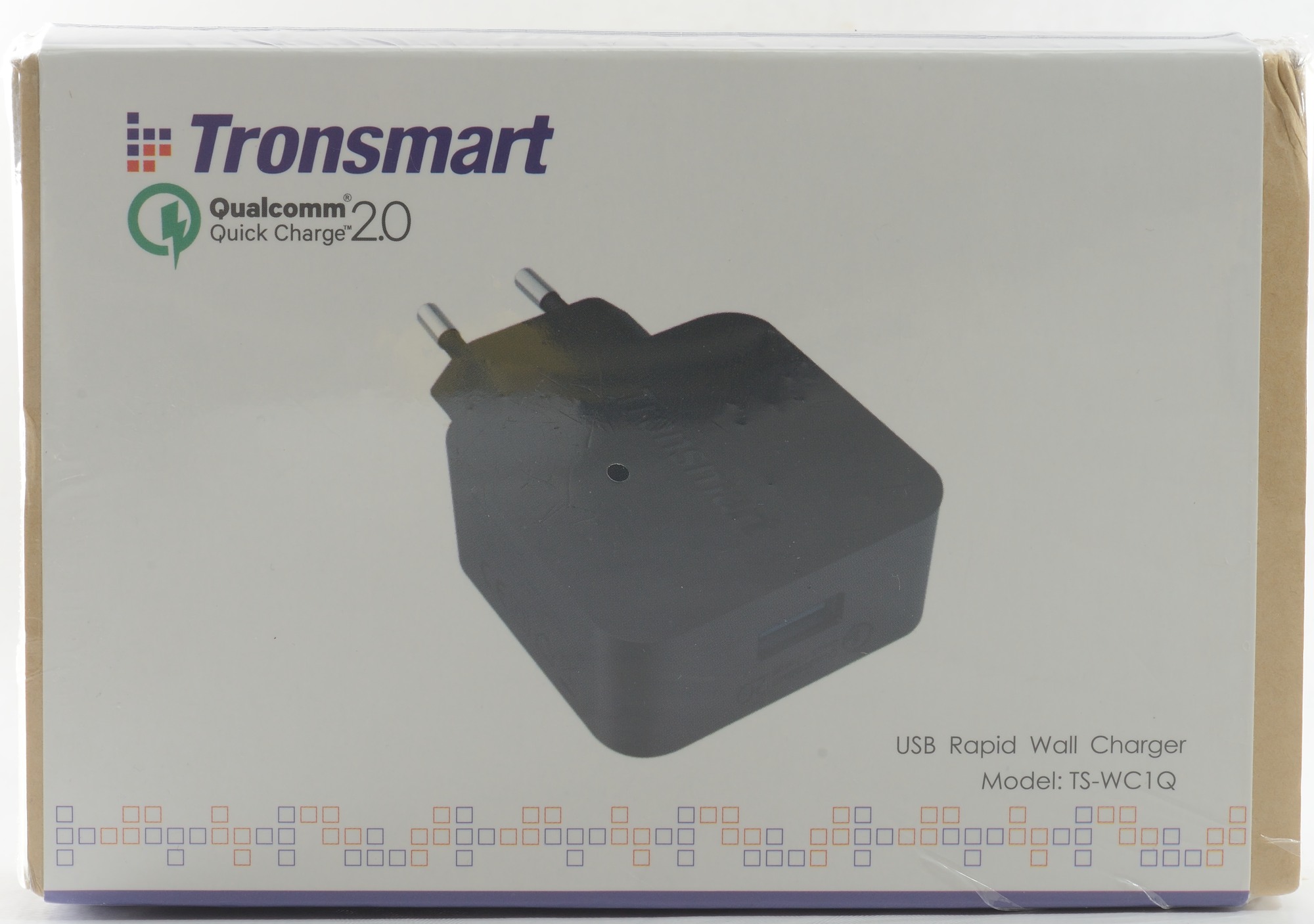
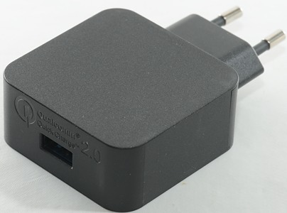
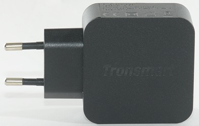
Tronsmart USB Rapid Wall charger TS-WC1Q
Official specifications:
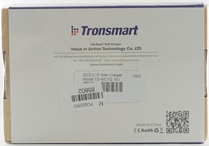
- Model: TS-WC1Q
- Input: 100-240V 50/60Hz
- Output: 5VDC 2A, 9VDC 2A, 12VDC 1.5A
- Power: 10 watt / 18 watt
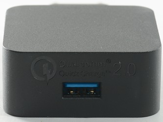
- QuickCharge 2.0
I got it from ebay dealer powerstrike
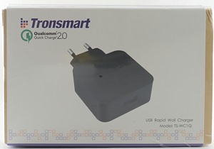
I got this charger in a cardboard retail box.
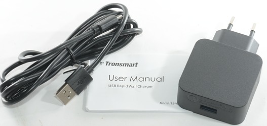
The box contained the charger, a usb cable and a manual.
Measurements
- Power consumption when idle is 0.06 watt
- Usb port coding is usb charger (DCP) and QuickCharge 2.0
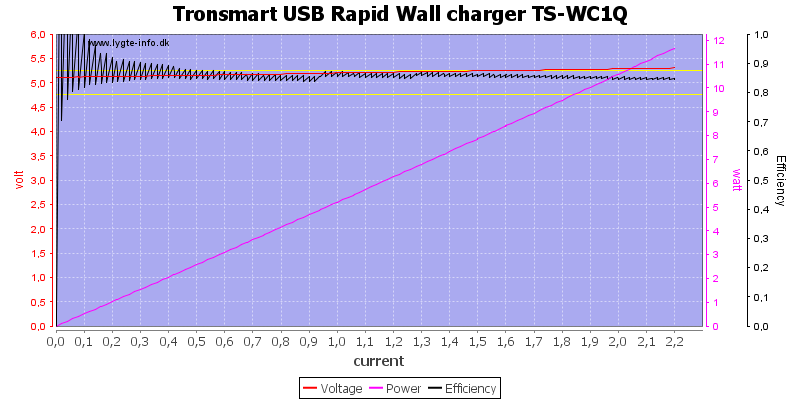
A 2A rated charger where the overload protection kicks in at 2.2A (nice). The efficiency is also good.
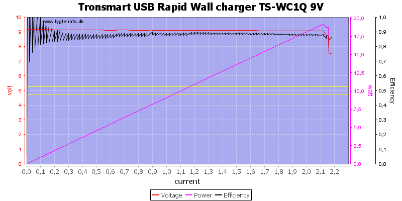
9V at 2A works fine.
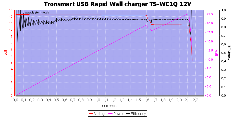
When doing QuickCharge at 12V it is rated for 1.5A and it can handle that without problems. At 1.6A the output voltage will drop a bit and at 2.1A the overload protection kicks in.
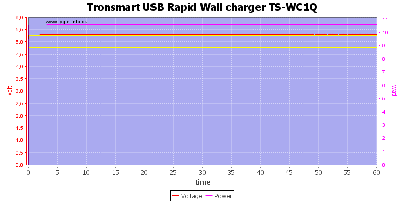
Running with 5V output and 2A load for an hour is no problem.
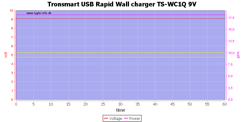
9V 2A for one hour is also fine.
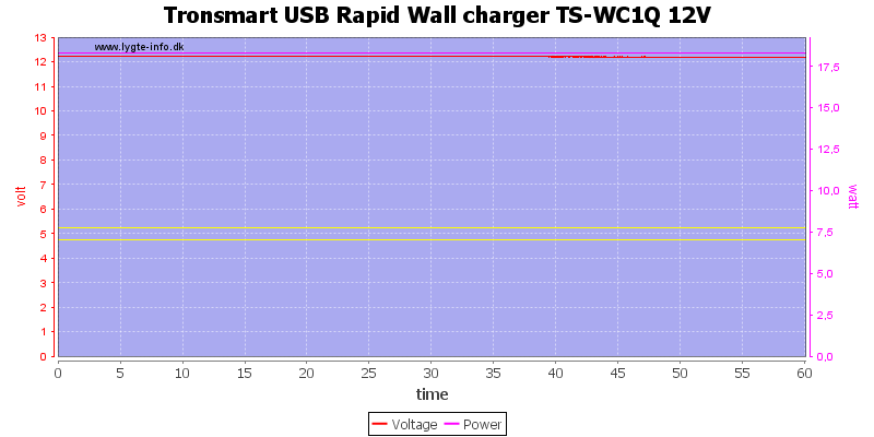
And the same with 12V 1.5A for one hour.
The temperature photos below are taken between 30 minutes and 60 minutes into the one hour test.
First four photes is from the 5V 2A test.
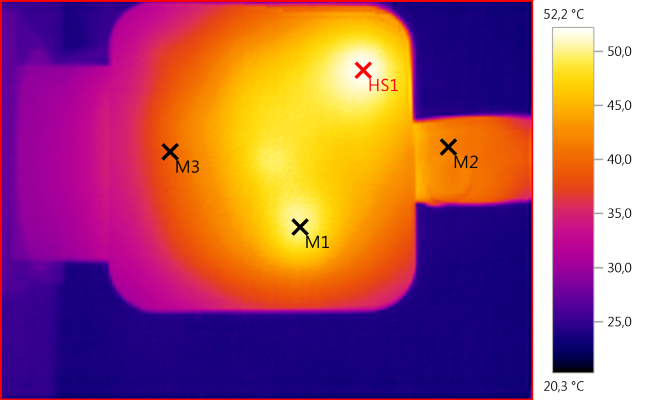
M1: 50,2°C, M2: 41,5°C, M3: 39,6°C, HS1: 52,2°C
HS1 is the rectifications mosfet and M1 is the big controller IC.
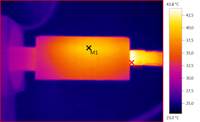
M1: 40,0°C, HS1: 43,8°C
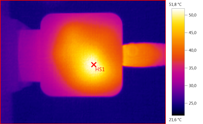
HS1: 51,8°C
Here HS1 is the transformer.
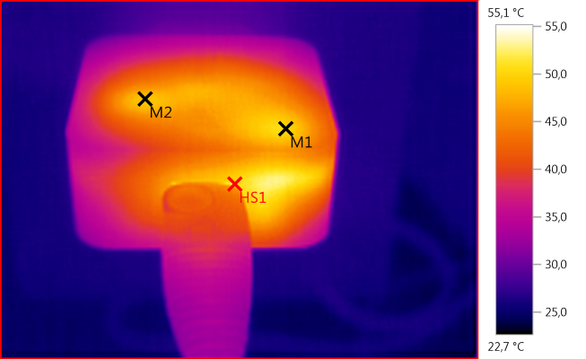
M1: 50,2°C, M2: 49,0°C, HS1: 55,1°C
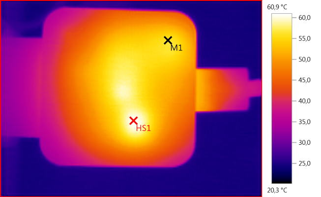
M1: 56,0°C, HS1: 60,9°C
This is from 12V 1.5A test, the switcher is warmer due to the higher output power.
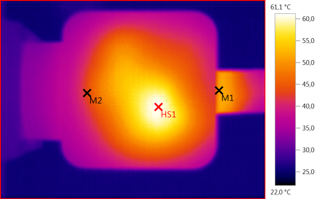
M1: 50,3°C, M2: 43,3°C, HS1: 61,1°C
This is from 12V 1.5A test, the transformer get warmer with the higher output power.
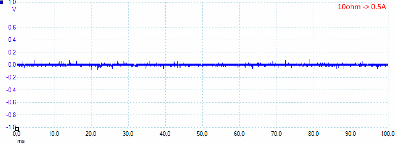
13mV rms and 240mVpp
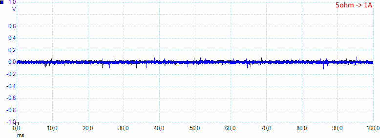
Increasing the load will also increase the noise: 17mV rms and 250mVpp
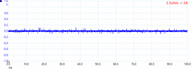
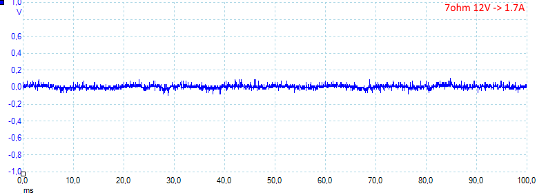
As above: 20mV rms and 410mVpp
With a slight overload the noise is still at a fairly low value: 22mV rms and 228mVpp
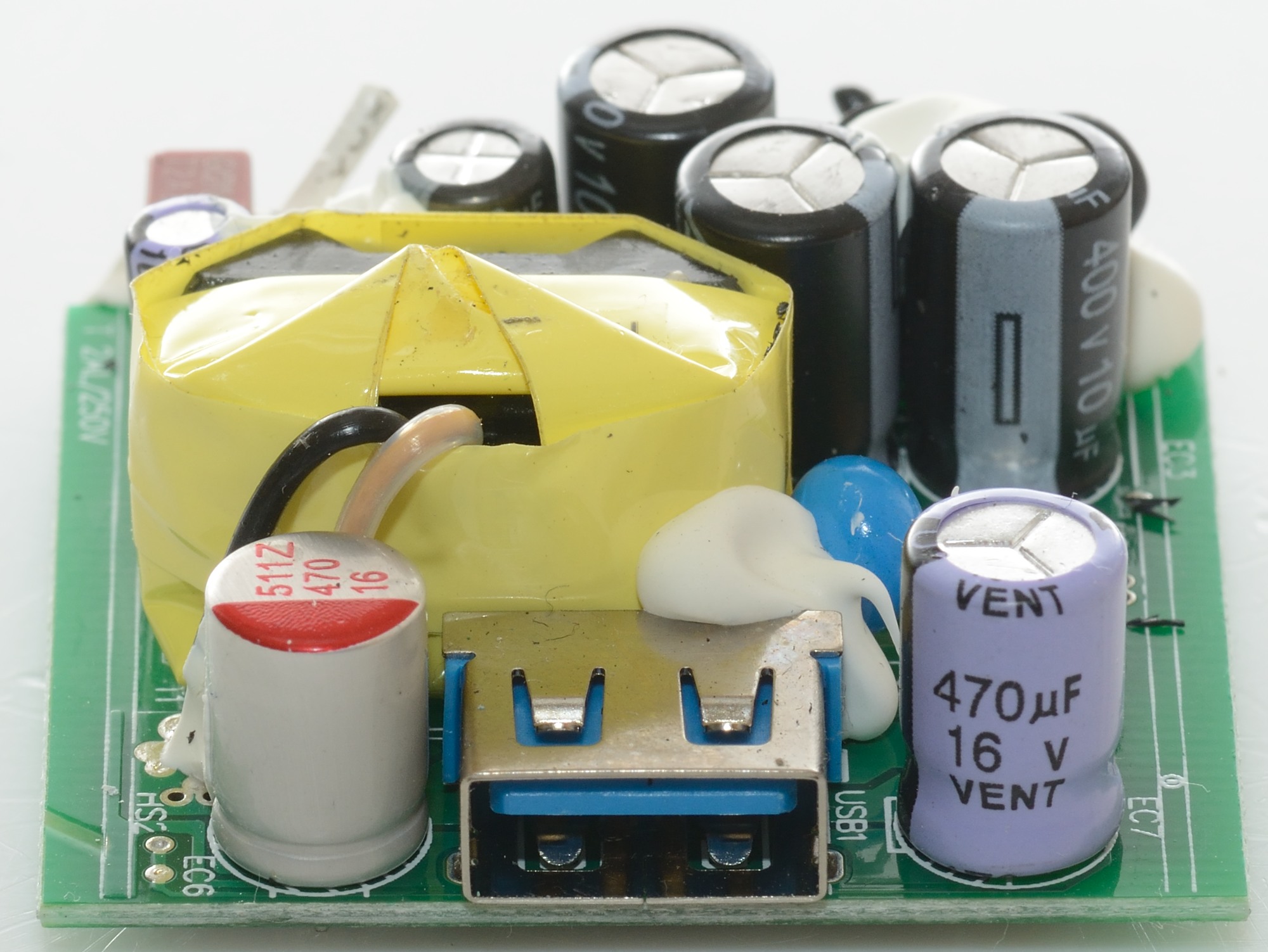
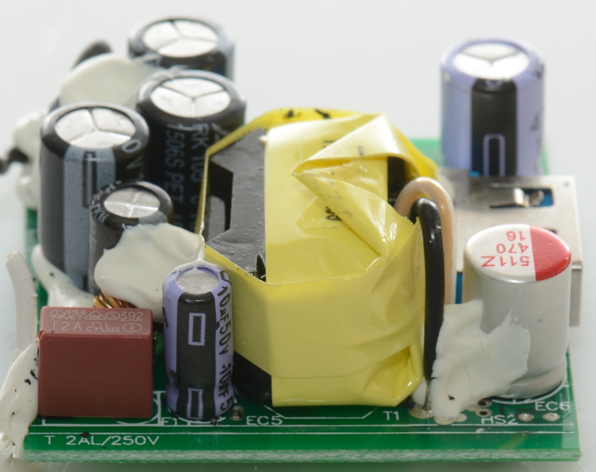
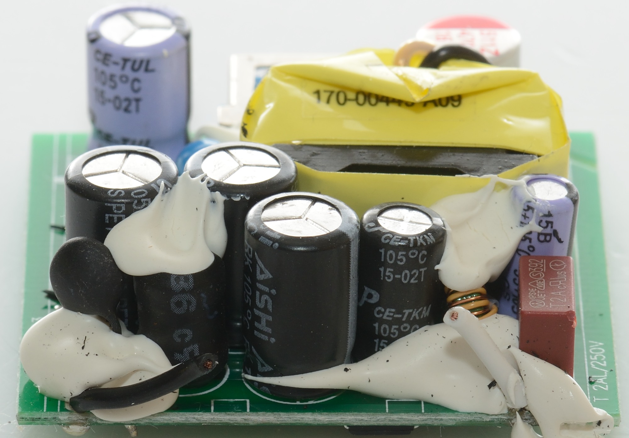
Tear down
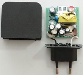
I could not open this charger with my vice or mallet and had to cut it open.
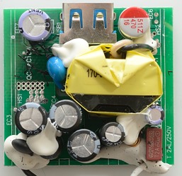
There is not that much too see on the topside, there is a fuse at the input and hidden in the white stuff is a common mode coil. There is a normal inductor at the input and a inrush limiter (NTC).
The blue safety capacitor is beside the transformer.

The red box is a 2A fuse.

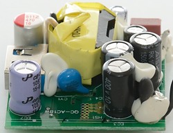
Behind the black wire is the inrush limiter and the inductor. The common mode coil can be seen beside the fuse.
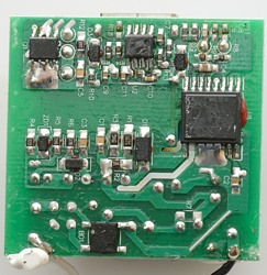
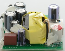
On the bottom side is the bridge rectifier and a huge IC (U1) that is mounted between mains and low volt side. This chip is a SC1223K that is a mains switcher and has output for synchronous rectification. The chip has very low standby power and is tested with 6000 volt, but it do not have any support for QuickCharge. This must be provided by U2 (Sorry, I could not read the number on it). Q1 is the mosfet used for synchronous rectification.
One likely candidate for U2 is PHY100, looking at the circuit it looks possible.
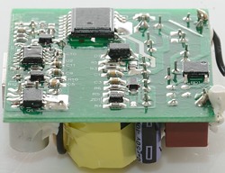
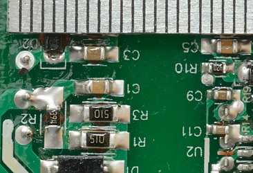
The isolation distance is good.
Testing with 2500 volt and 5000 volt between mains and low volt side, did not show any safety problems.
Conclusion
This is a good charger with QuickCharge support, overload protection looks fine, the noise levels are good, it has high efficiency and low standby current.
Notes
Index of all tested USB power supplies/chargers
Read more about how I test USB power supplies/charger