UGreen Dual USB Power Adapter CD104
Official specifications:
- Model no: CD104
- Product name: Dual USB charger
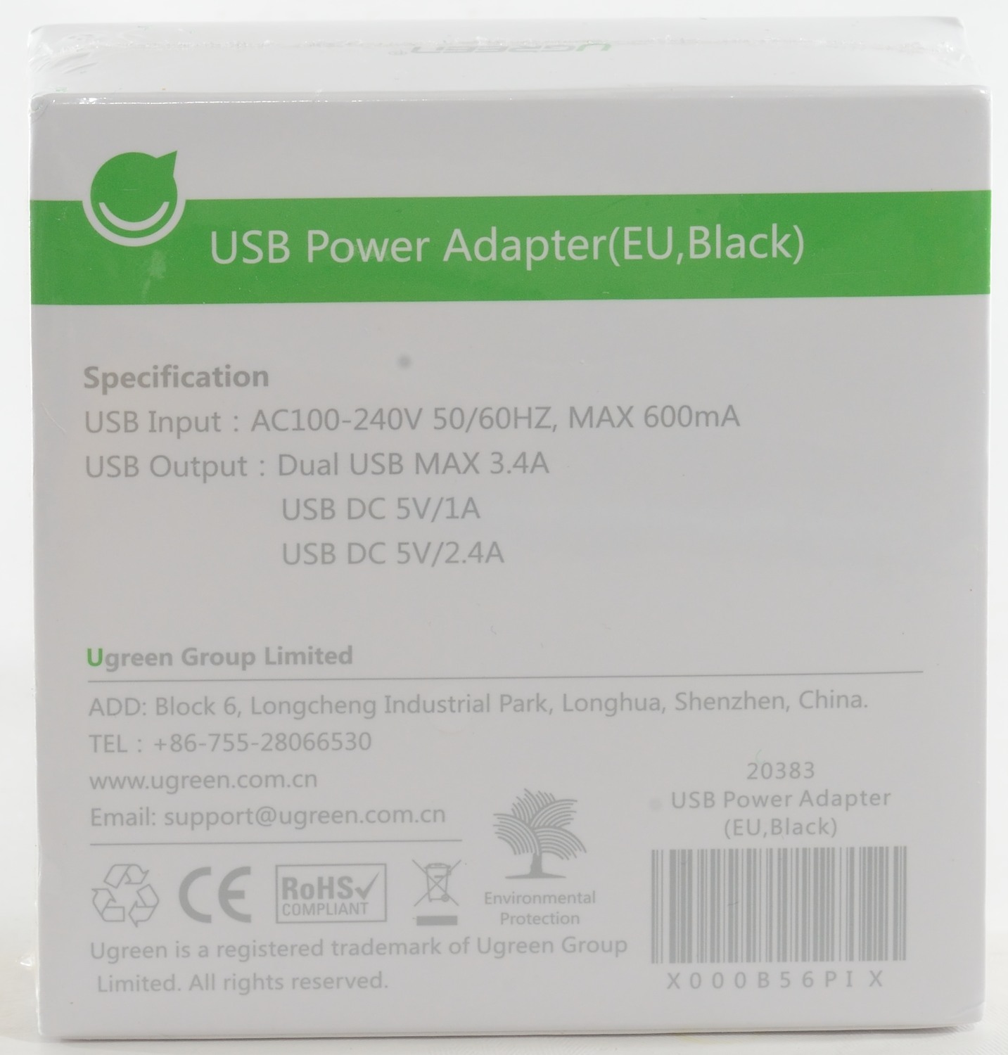
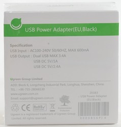
- Input: 100-240VAC 50/60Hz, max 600mA
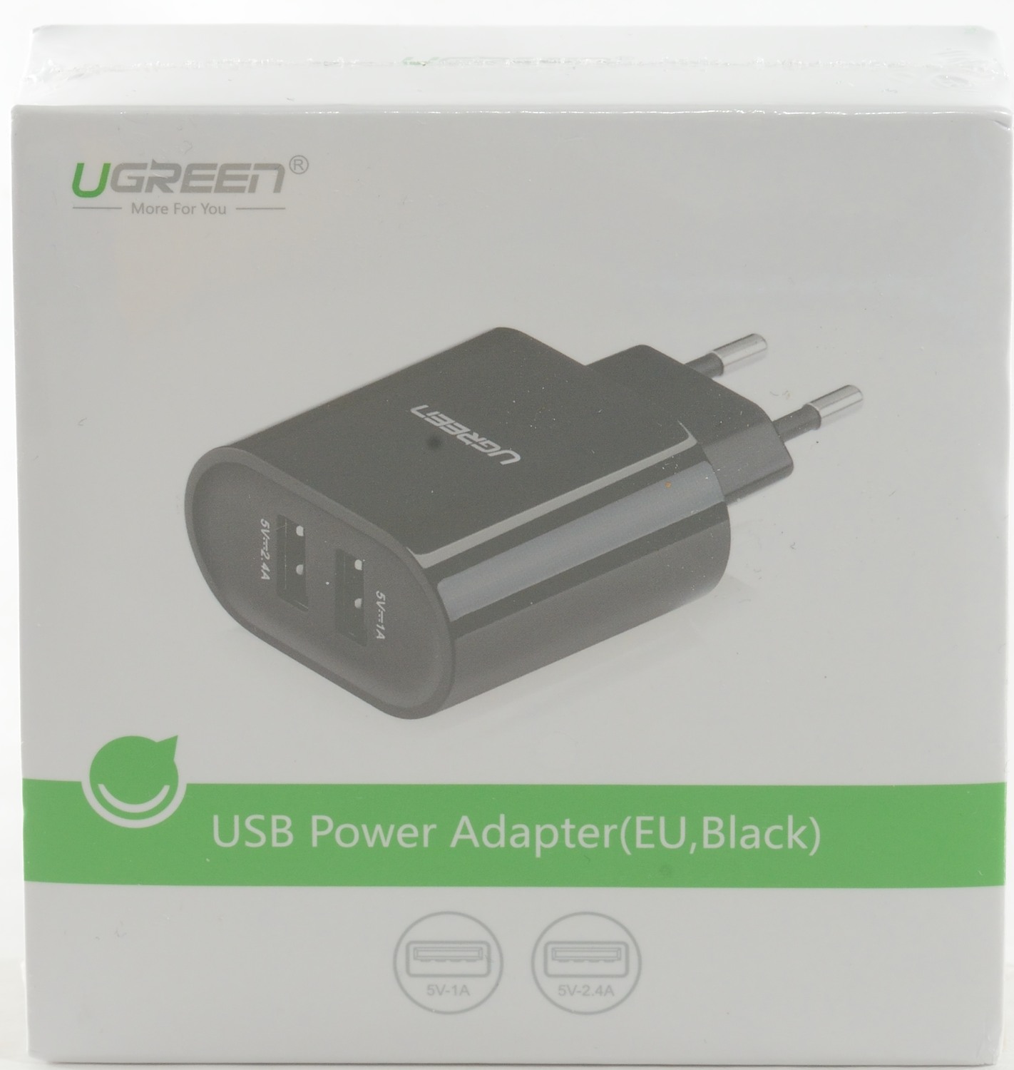
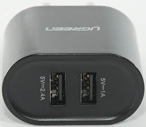
- Output: 5V/2.4A + 5V/1A
- Material: ABS+ PC fireproof
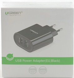
I got it in a white cardboard box.
Measurements
- Power consumption when idle is 0.08 watt
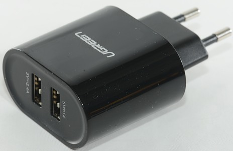
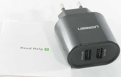
- USB output top is auto coding with Apple 1A.
- USB output bottom is auto coding with Apple 2.4A as max.
- The two outputs are in parallel.
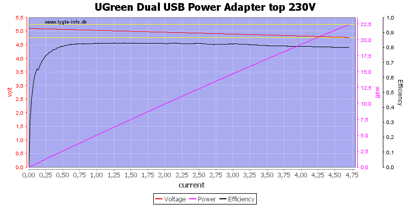
The top output may only be rated for 1A, but it can deliver a bit above 4.5A, this is a bit high for the usb connector.
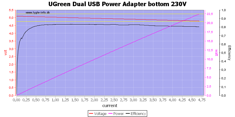
Same with the bottom output.

And it is no surprise that running them in parallel, the output current is the same, both at 120VAC
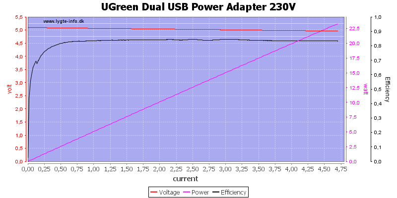
And 230VAC
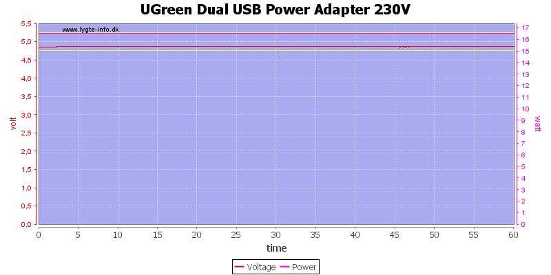
Rated output is 3.4A and it can deliver that for at least one hour.
The temperature photos below are taken between 30 minutes and 60 minutes into the one hour test.
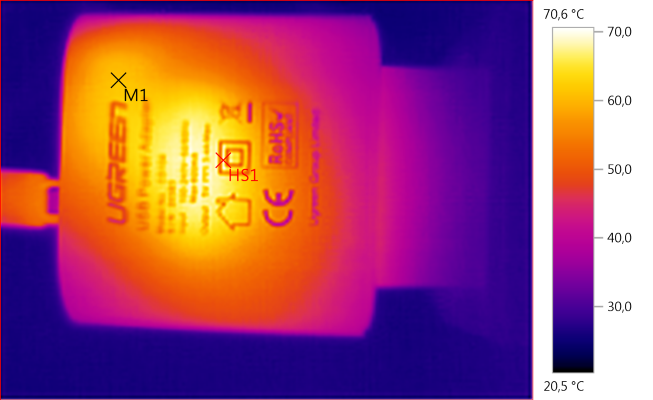
M1: 61,2°C, HS1: 70,6°C
HS1 is the transformer.
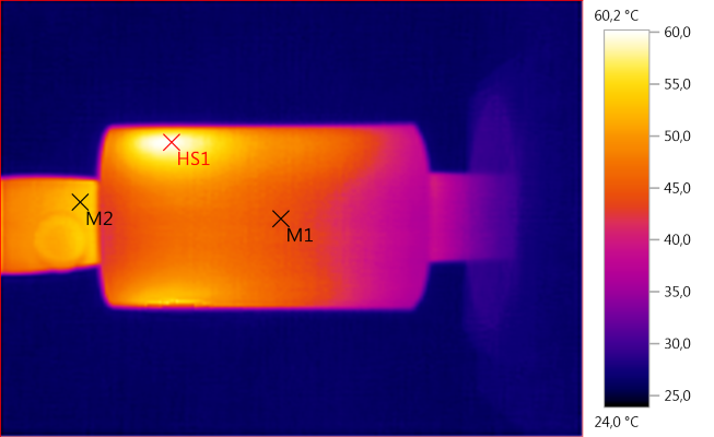
M1: 44,5°C, M2: 52,9°C, HS1: 60,2°C
HS1 is the rectifier diode, is is also the reason for the warm usb connector.
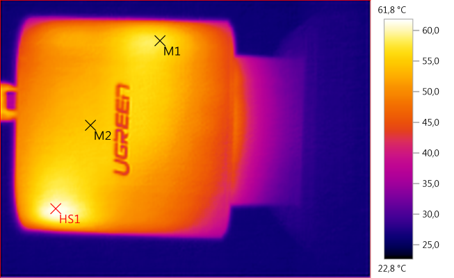
M1: 57,7°C, M2: 54,4°C, HS1: 61,8°C
HS1 is again the rectifier diode. M1 is the switcher transistor or something close to it.
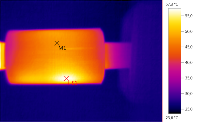
M1: 47,7°C, HS1: 57,3°C
HS1 is the switcher transistor or something close to it.
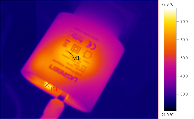
M1: 62,0°C, HS1: 77,3°C
M1 is the transformer and HS1 is due to the rectifier diode.
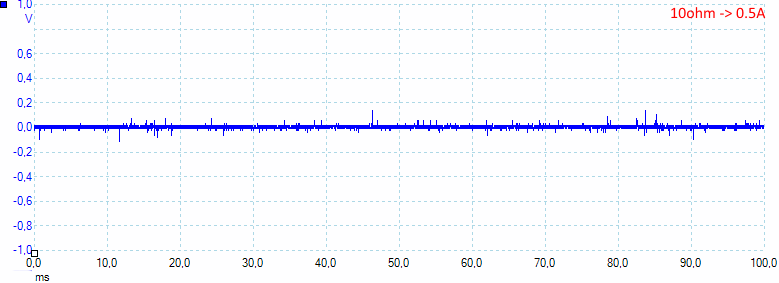
At 0.5A the noise is 13mV rms and 331mVpp.
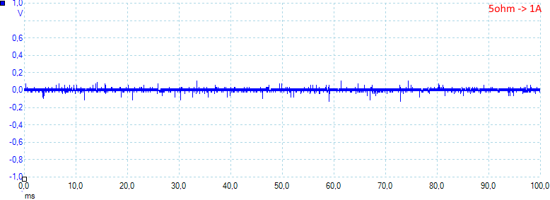
At 1A the noise is 16mV rms and 305mVpp.
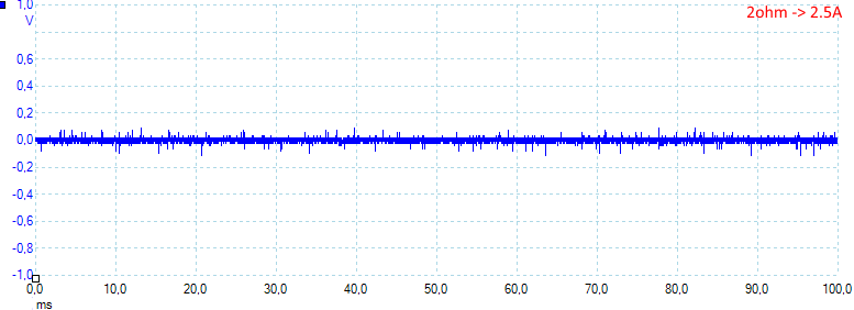
At 2.5A the noise is 18mV rms and 273mVpp.
Tear down
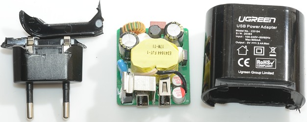
The glue was very strong on this one, I had to cut and break it open.
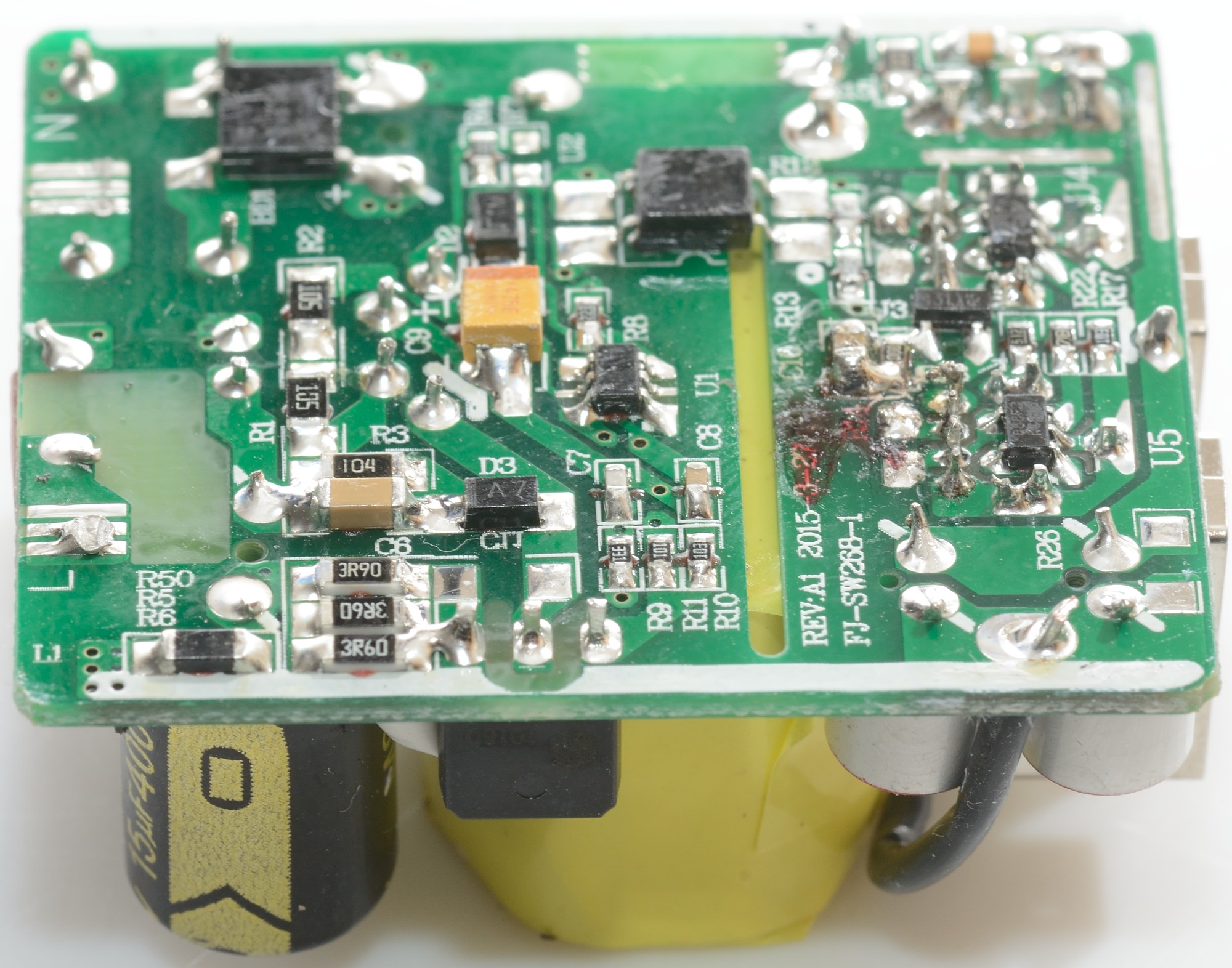
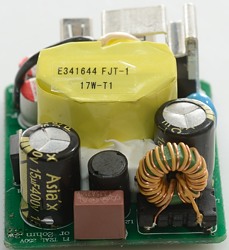
On the input side is a fuse (Red block), a common mode coil and an inductor. The switcher transistor can also be seen.
The transfor has flying leads to improve isolation,below the transformer is a safety capacitor.
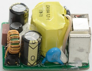
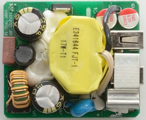
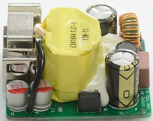
On the first picture the common mode could and the safety capacitor with all its approvals can be seen. The metal is a heatsink for the rectifier diode. On the second picture the fuse with the inductor behind it and the common mode coil can be seen.
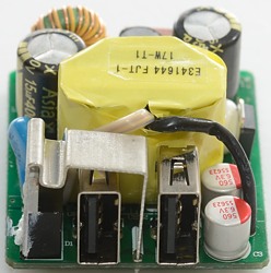
On the first picture the switcher transistor sits before the transformer. On the second picuture the recifier diode can be seen inside the heatsink. The heatsink also helps move current to the capacitors.

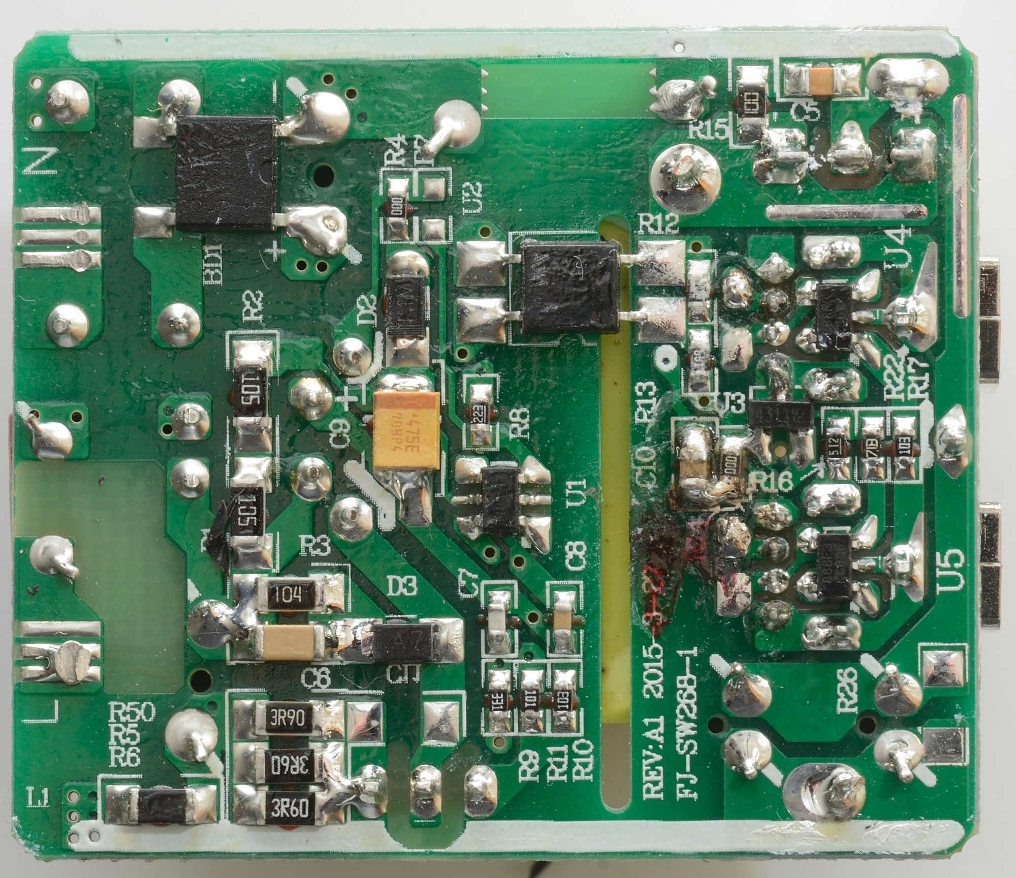
On this side is the bridge rectifier (BD1), the switcher controller (U1), the opto feedback (U2), the reference (U3:431) and two chips for auto coding (U4, U5).

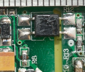
The slot in the circuit board is great for safety, this means very good distance between mains and low volt side.
Testing with 2830 volt and 4242 volt between mains and low volt side, did not show any safety problems.
Conclusion
This power supply can deliver rated current, has auto coding, noise is acceptable, there is overload protection (It is a bit high, but not enough to be a serious problem), the safety looks good.
I will call it a good power supply.
Notes
Index of all tested USB power supplies/chargers
Read more about how I test USB power supplies/charger
How does a usb charger work?