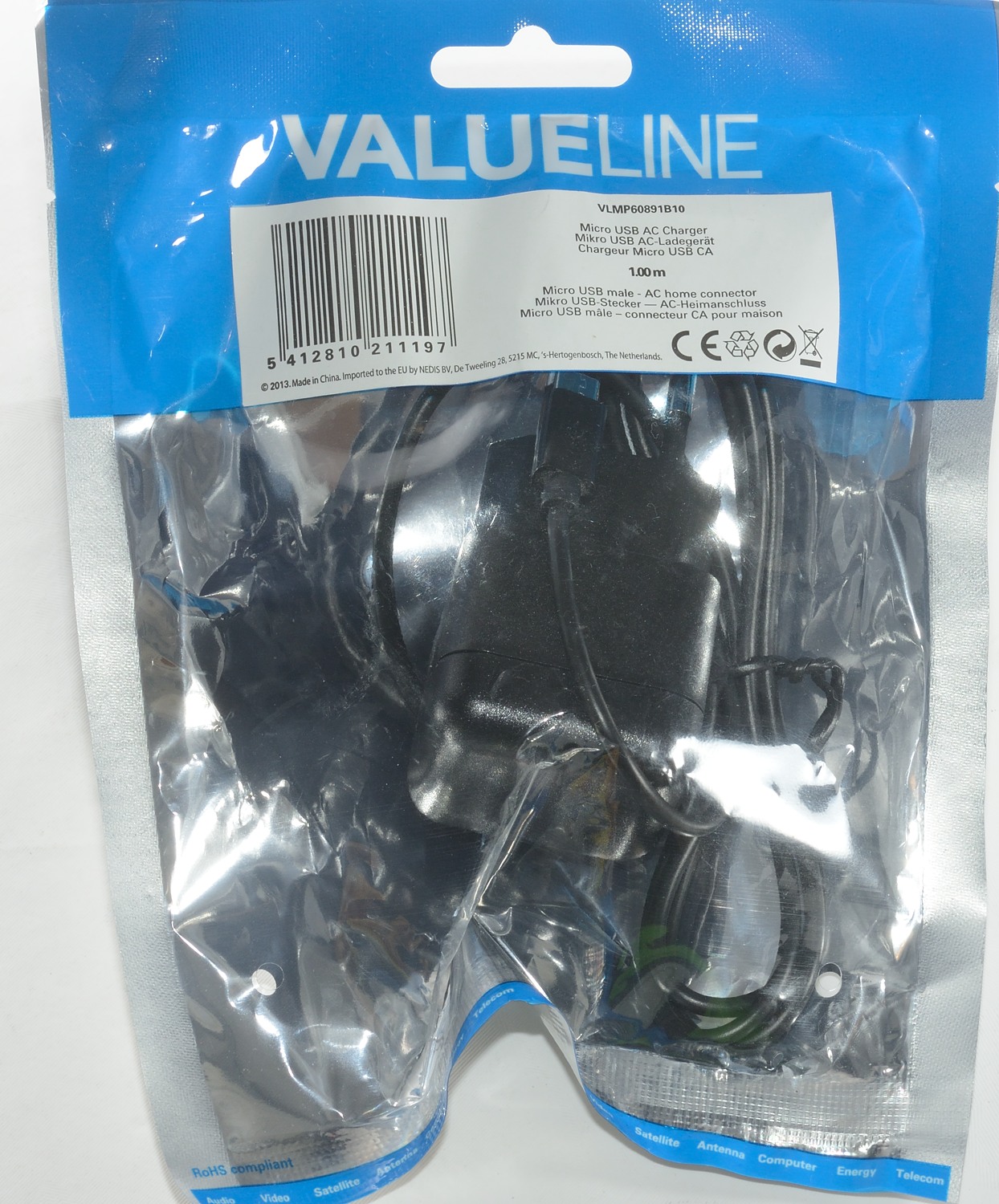
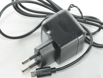
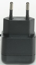
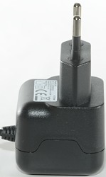
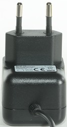
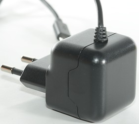
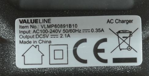
Valueline Micro USB AC charger VLMP60891B10
Official specifications:
- Input Power: AC 100-240V 50/60Hz
- Output Power: DC 5V-2.1A
- Connector: Micro usb
I got it in a plastic bag.
Measurements
- Power consumption when idle is 0.1 watt
- Usb output is coded as Samsung
- Weight: 64.6g
- Size: 71.7 x 48.0 x 39.0mm
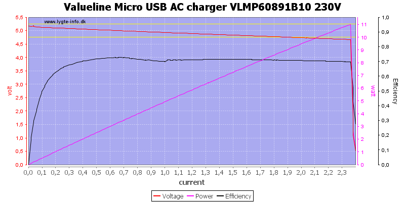
Thus small adapter can deliver the rated current and a bit more (the overload protection looks fine). The dropping voltage is probably due to the cable.
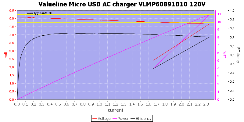
It will also work at 120VAC.
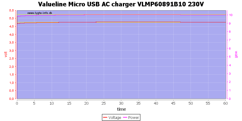
No problems running one hour at 2.1A.
The temperature photos below are taken between 30 minutes and 60 minutes into the one hour test.
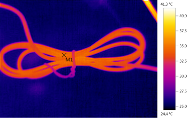
M1: 35,4°C
The cable gets sligtly warm.
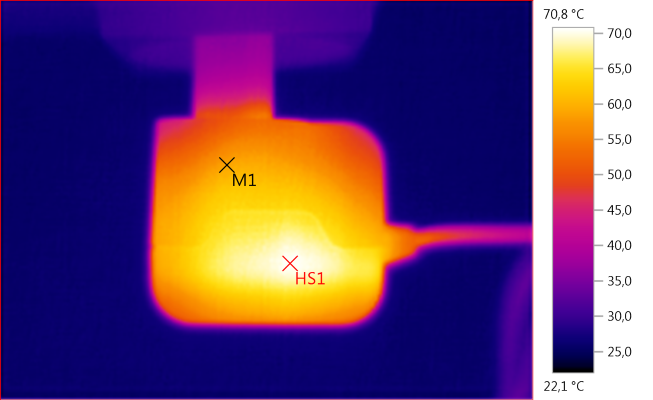
M1: 58,8°C, HS1: 70,8°C
HS1 is the transformer.
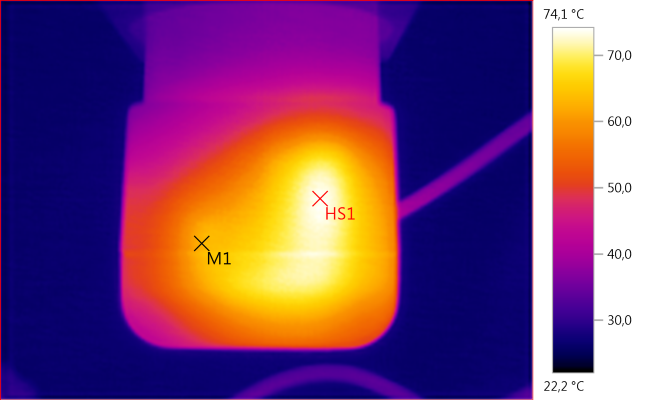
M1: 62,6°C, HS1: 74,1°C
HS1 is again the transformer.
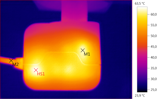
M1: 61,8°C, M2: 52,8°C, HS1: 63,5°C
This time HS1 is the rectifier diode.
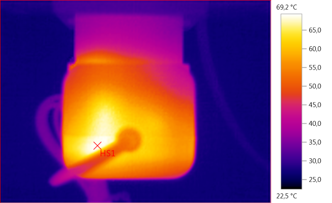
HS1: 69,2°C
And the rectifier diode again.
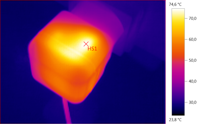
HS1: 74,6°C
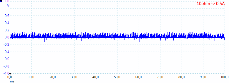
At 0.5A the noise is 32mV rms and 303mVpp.
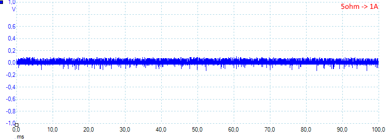
At 1A the noise is 34mV rms and 275mVpp.
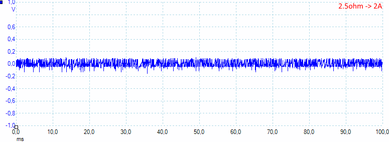
At 2A the noise is 44mV rms and 273mVpp.
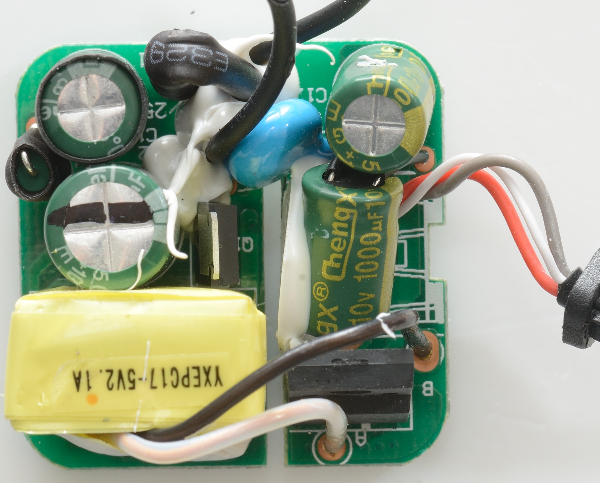
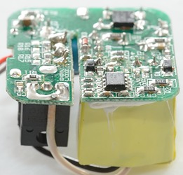
Tear down
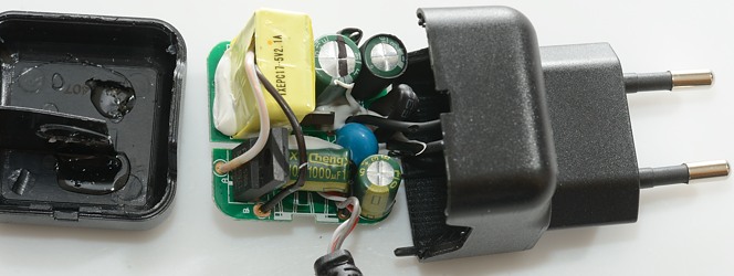
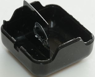
My vice and a mallet could open it.
The plastic shield inside the box is used for isolation between mains and low volt side.

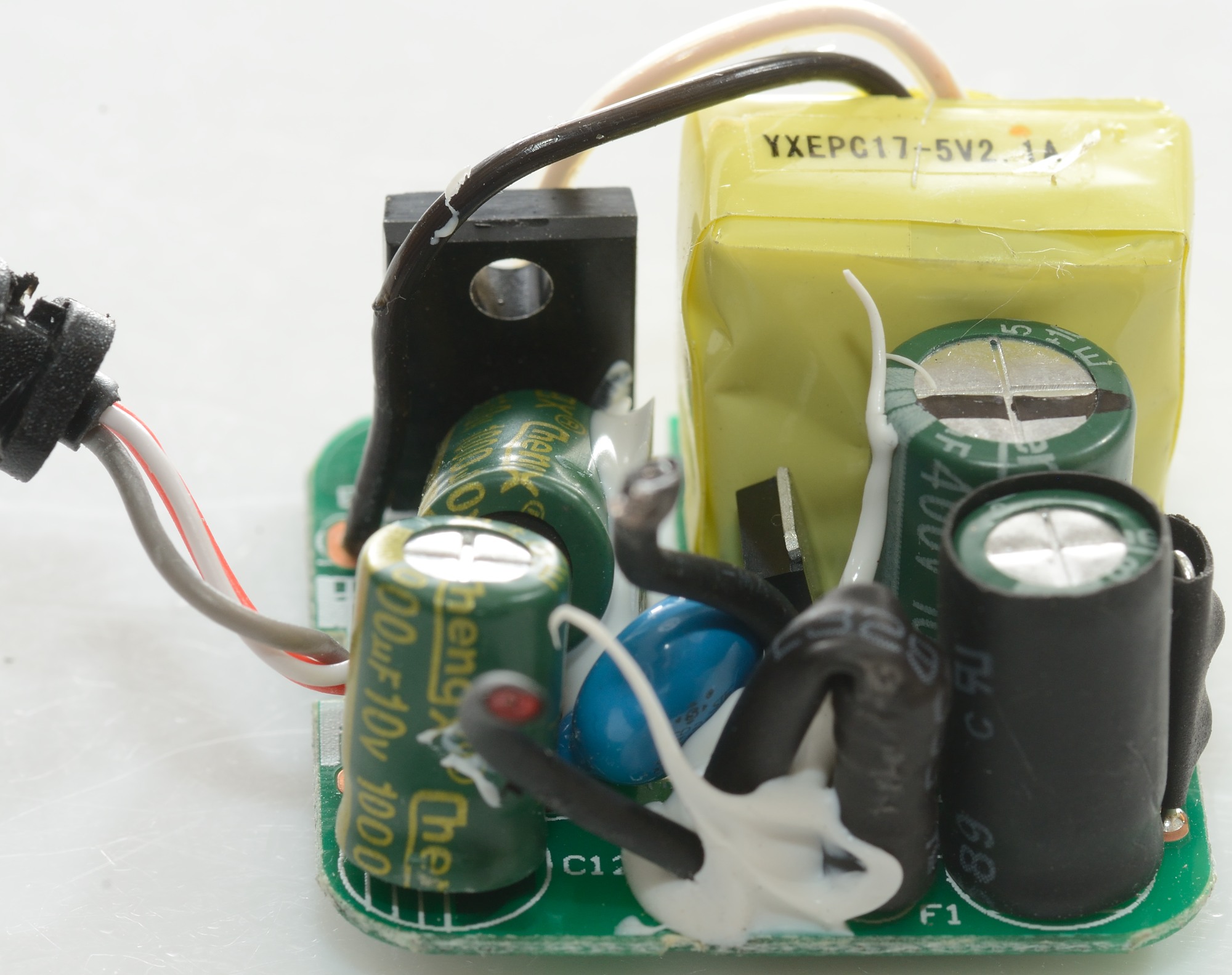
At the mains input there is a fuse and a blue safety capacitor. Between the two capacitors is an inductor with shrink wrap around. The mains switcher transistor (Q1) is next to the transformer. The transformer has wires to the low volt side, where the rectifier diode is placed.
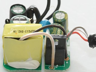
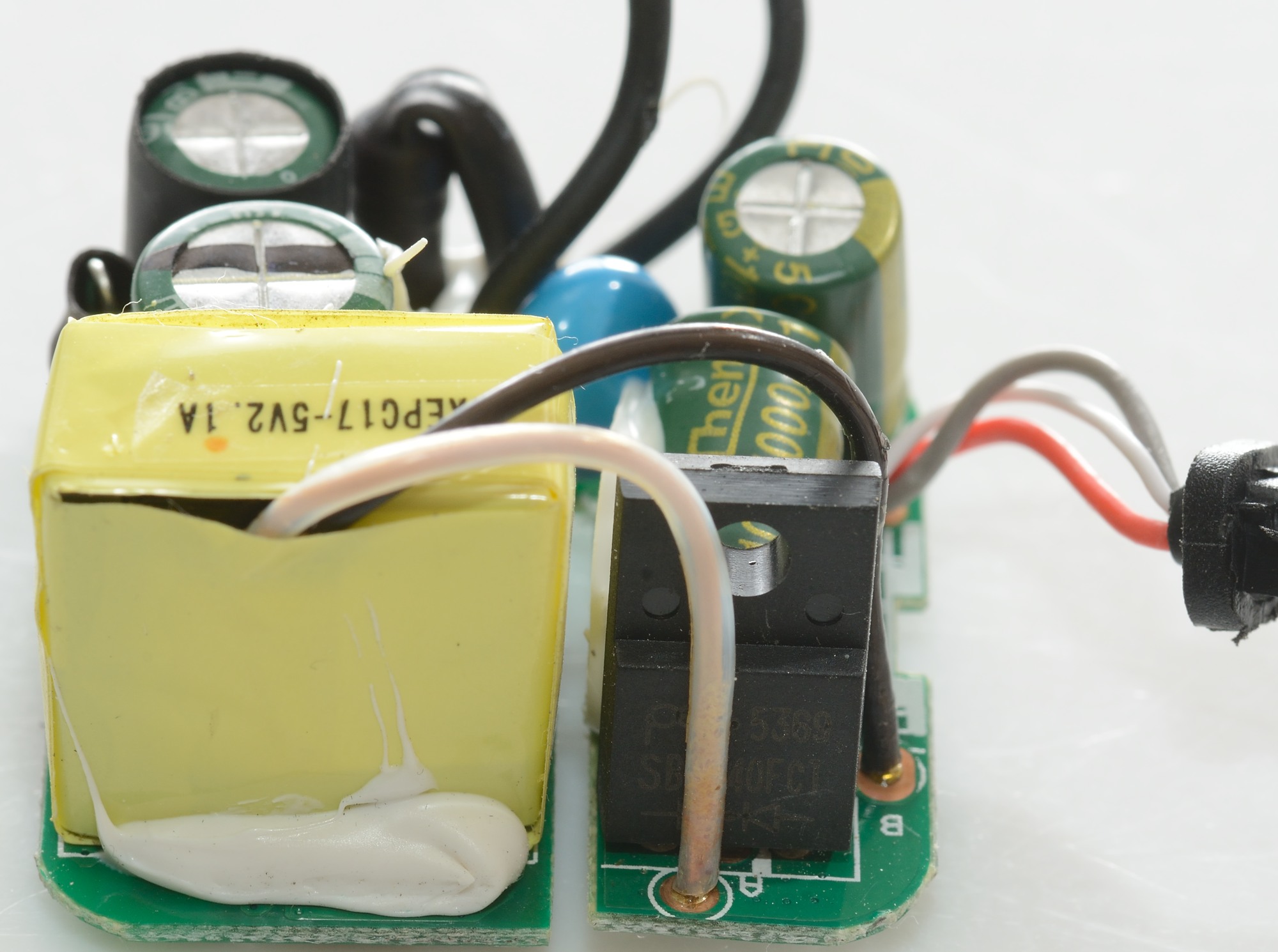
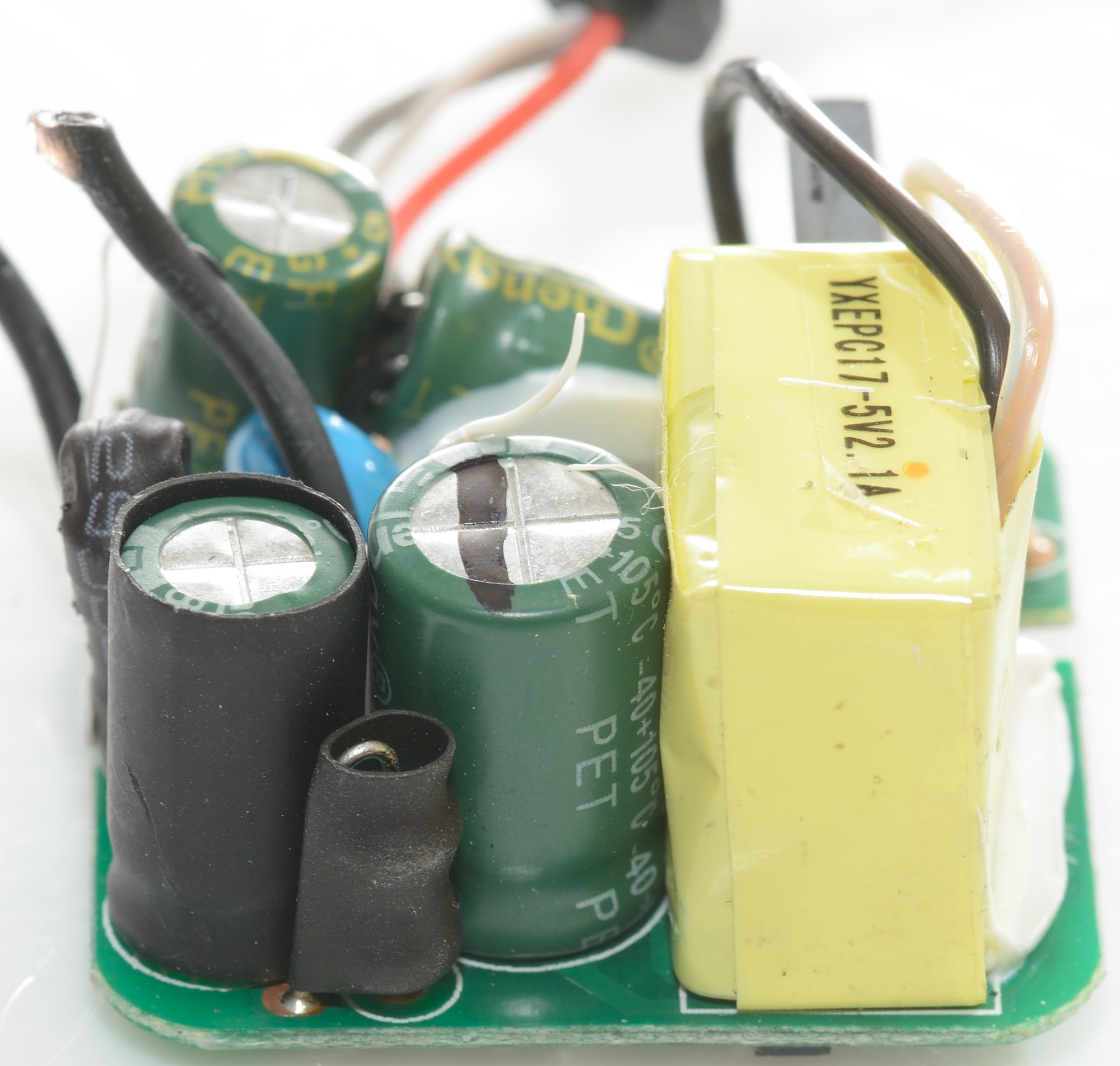
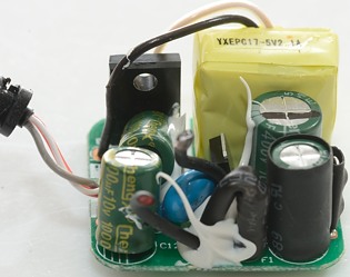
From this side the rectifier diode and the transformer can be seen.
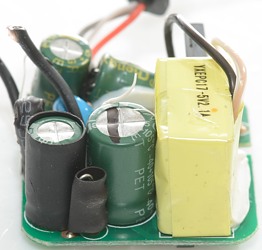
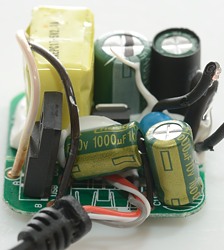
Here the inductor between the two mains capacitors can be seen. One of the capacitors has shrink wrap on top of the plastic isolation.
The fuse (F1) is next to the mains input wire.
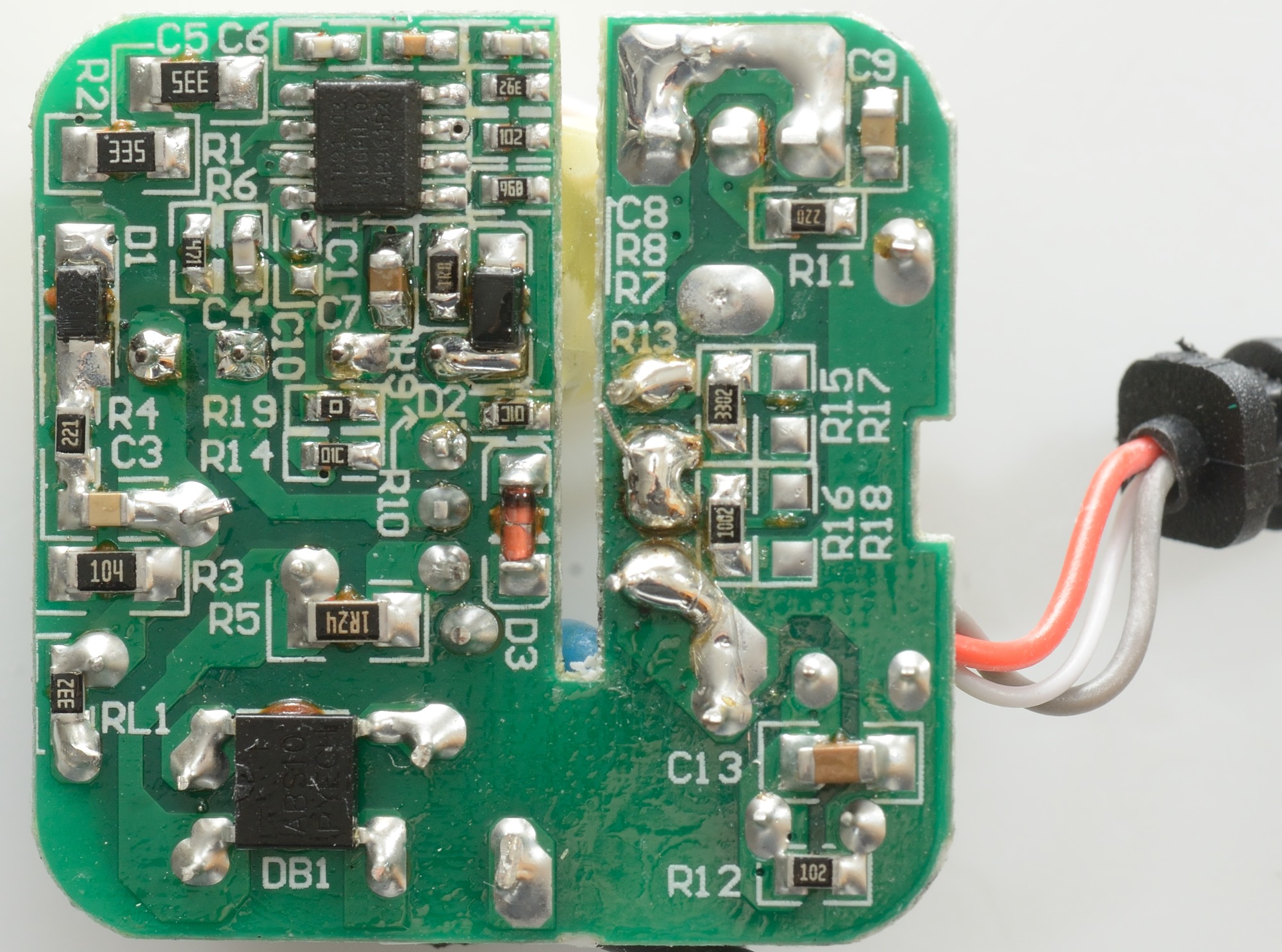
The circuit board is made for a usb connector, but this time 3 wires are connected instead.
The 3 wires are plus, minus and both data in one wire, this is used for coding the usb output.
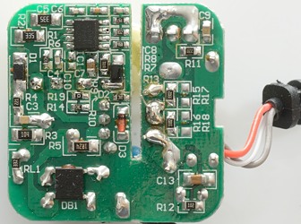
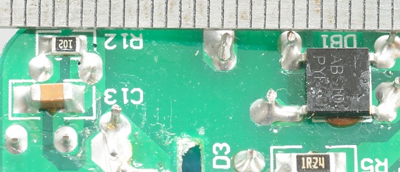
This side contains a bridge rectifier (DB1) and the mains switcher controller. There is two resistor for coding the usb output (R15, R16).
Safety distance looks good.
The charger failed testing with 2830 volt and 4242 volt, I was very surprised about that, the design looks good enough.
Conclusion
Generally this small charger looks well designed and with good performance, but due to the isolation fault it will not recommend it.
Notes
Charger was supplied by Pro backup (probackup.nl)
Index of all tested USB power supplies/chargers
Read more about how I test USB power supplies/charger
How does a usb charger work?