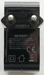
Voltcraft SPS-2400-2+
Official specifications:
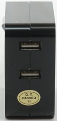
- USB outputs:2 x
- Power: 24 W
- Mains voltage: 115 V/AC, 230 V/AC
- Mains voltage range: 100 - 240 V/AC
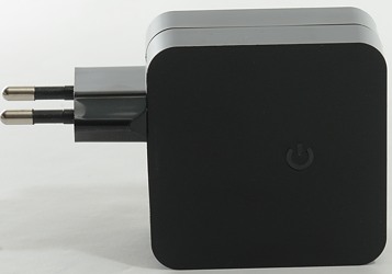
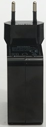
- Size: Width: 97mm, height: 60mm, length: 30mm
- Output current each output: 2400 mA
- Total output current: 4800 mA
I got it from Conrad
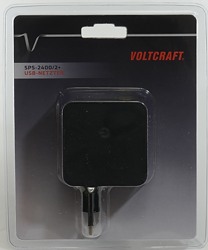
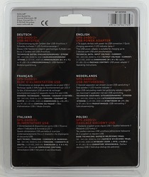
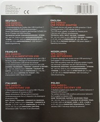
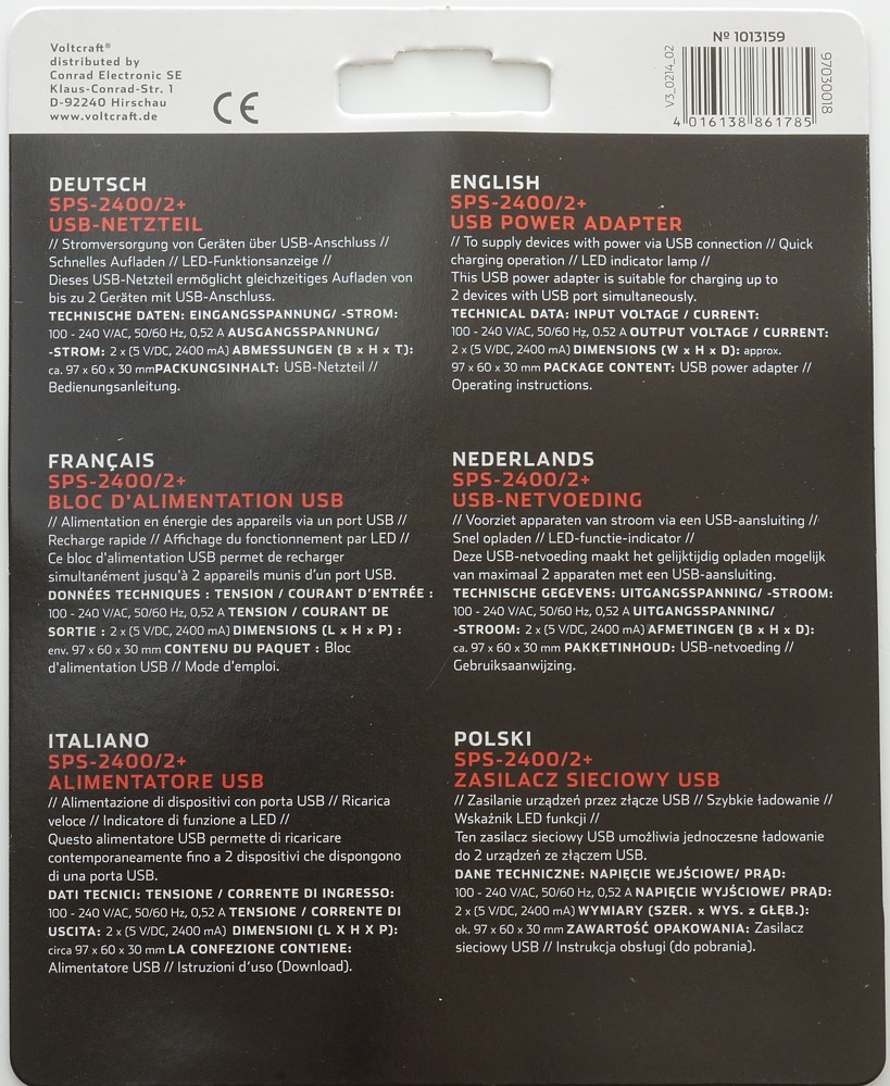
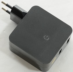
I got this charger in a blister pack.
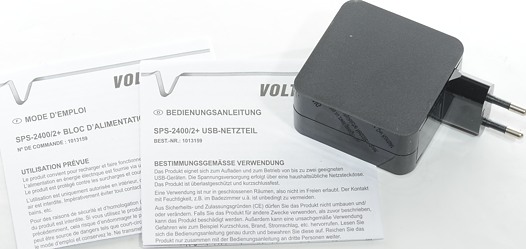
With charger and a instruction sheet in many languages.
Measurements
- Unloaded power consumption 0.1 watt
- Both USB output is coded as Apple 2.5A.
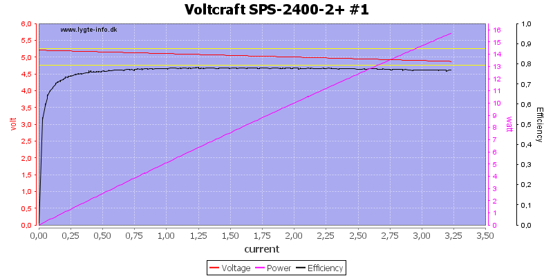
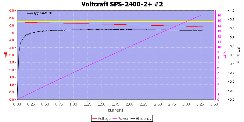
Both outputs can each deliver 3.2A before they shot down, this is a bit high for a 2.5A output, but acceptable
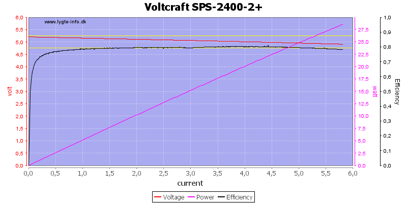
Running both in parallel I get 5.5A. The reason I do not get double is probably small resistance differences in the connections.
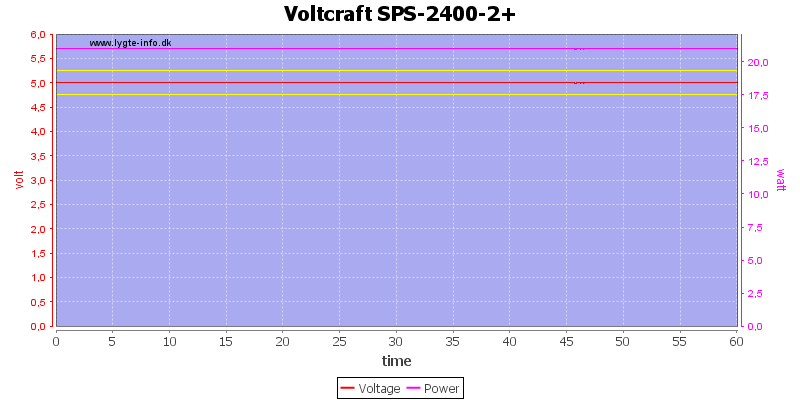
Running with a total load of 4.2A for one hour did not show any problems.
The temperature photos below are taken between 30 minutes and 60 minutes into the one hour test.
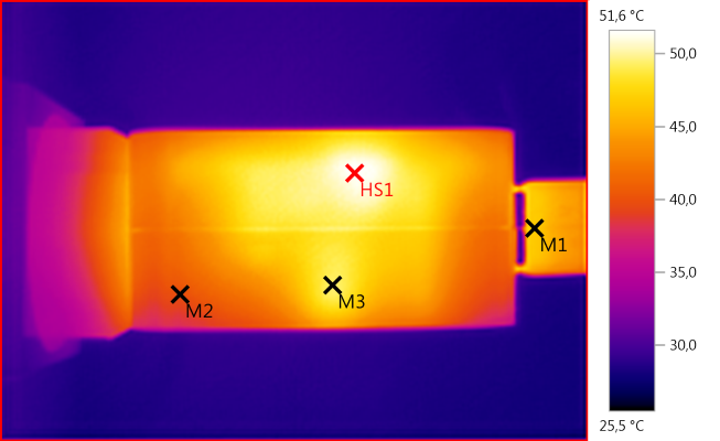
M1: 46,7°C, M2: 39,8°C, M3: 49,3°C, HS1: 51,6°C
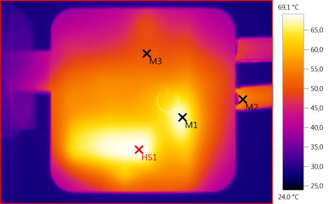
M1: 67,9°C, M2: 55,2°C, M3: 50,5°C, HS1: 69,1°C
HS1 is the mains transformer and M1 is the rectifier.
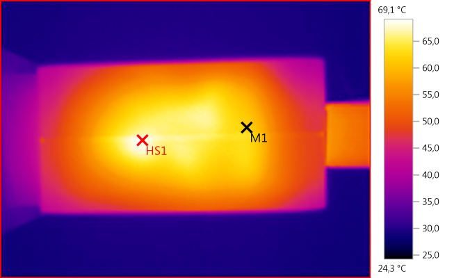
M1: 62,1°C, HS1: 69,1°C
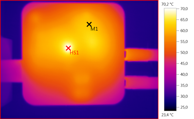
M1: 61,6°C, HS1: 70,2°C
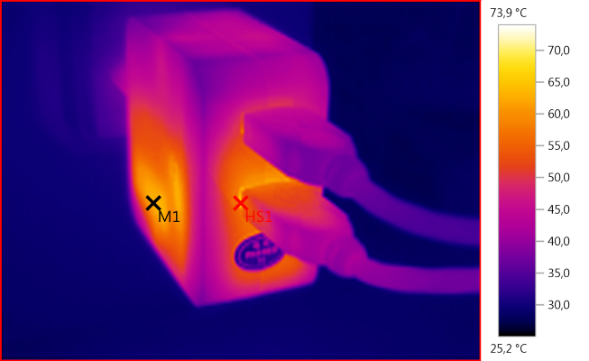
M1: 62,9°C, HS1: 73,9°C
The rectifier is heating the usb connector.
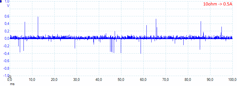
There is a lot of peak noise with 30mV rms and 1100mVpp.
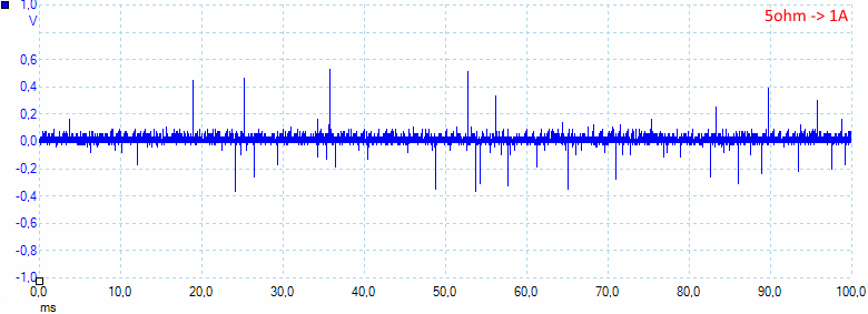
Increasing the current to 1A do not change anything 34mV rms and 1100mVpp.
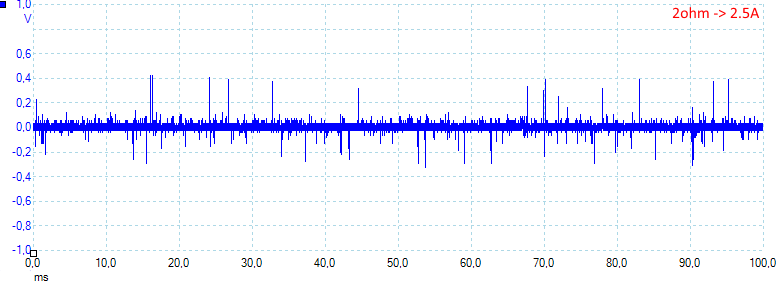
At 2.5A the noise is slightly lower with 41mV rms and 920mVpp.

But at maximum load it is very bad: 70mV rms and 1700mVpp.
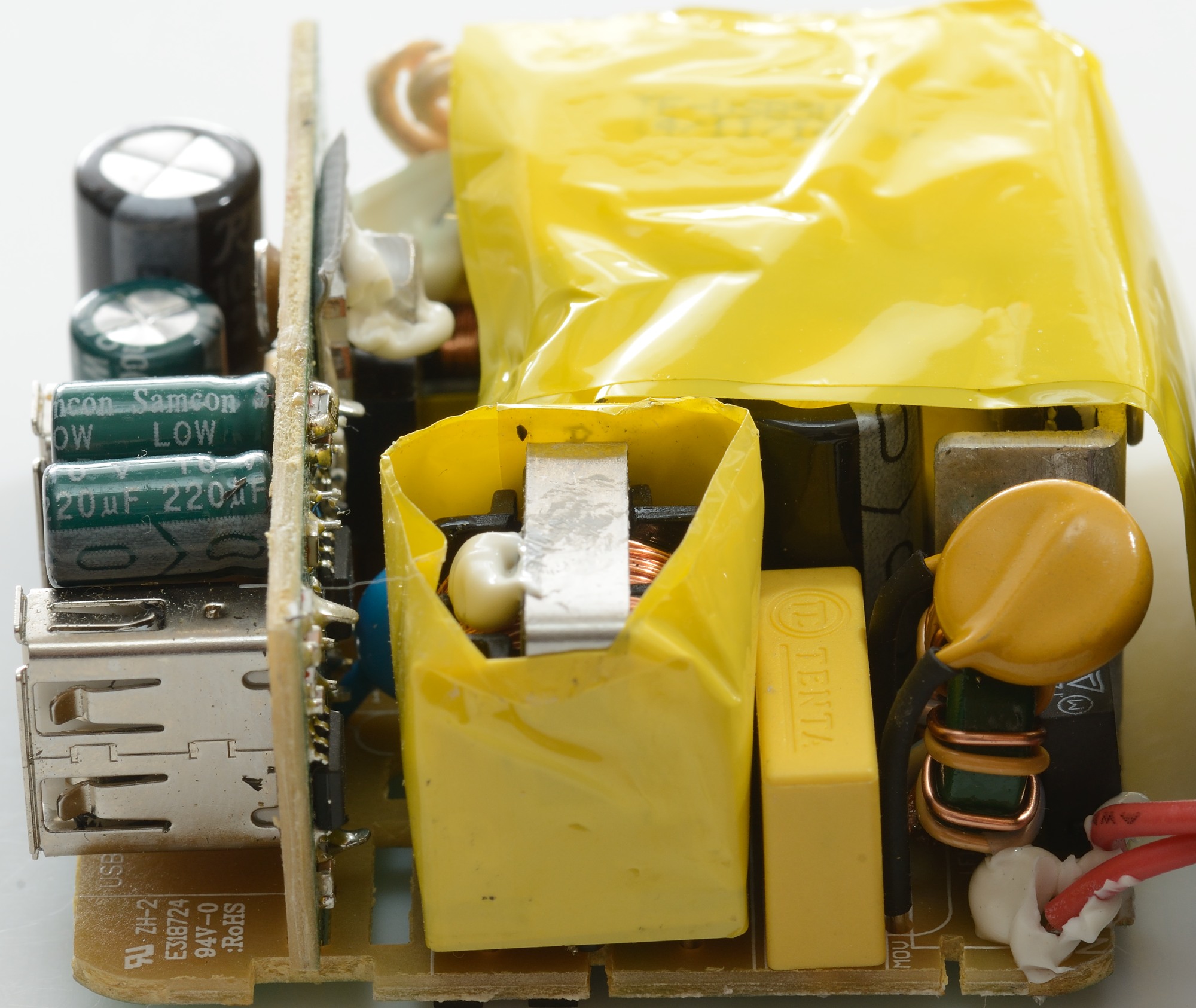
Tear down
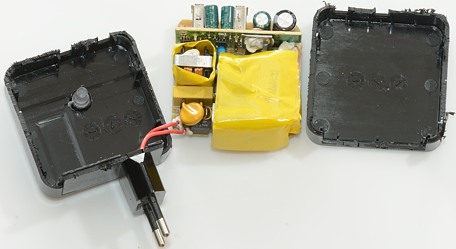
It looked like I could pop it open with my vice, but no, neither vice or hammer could open it. I had to cut (very good).
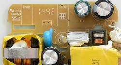
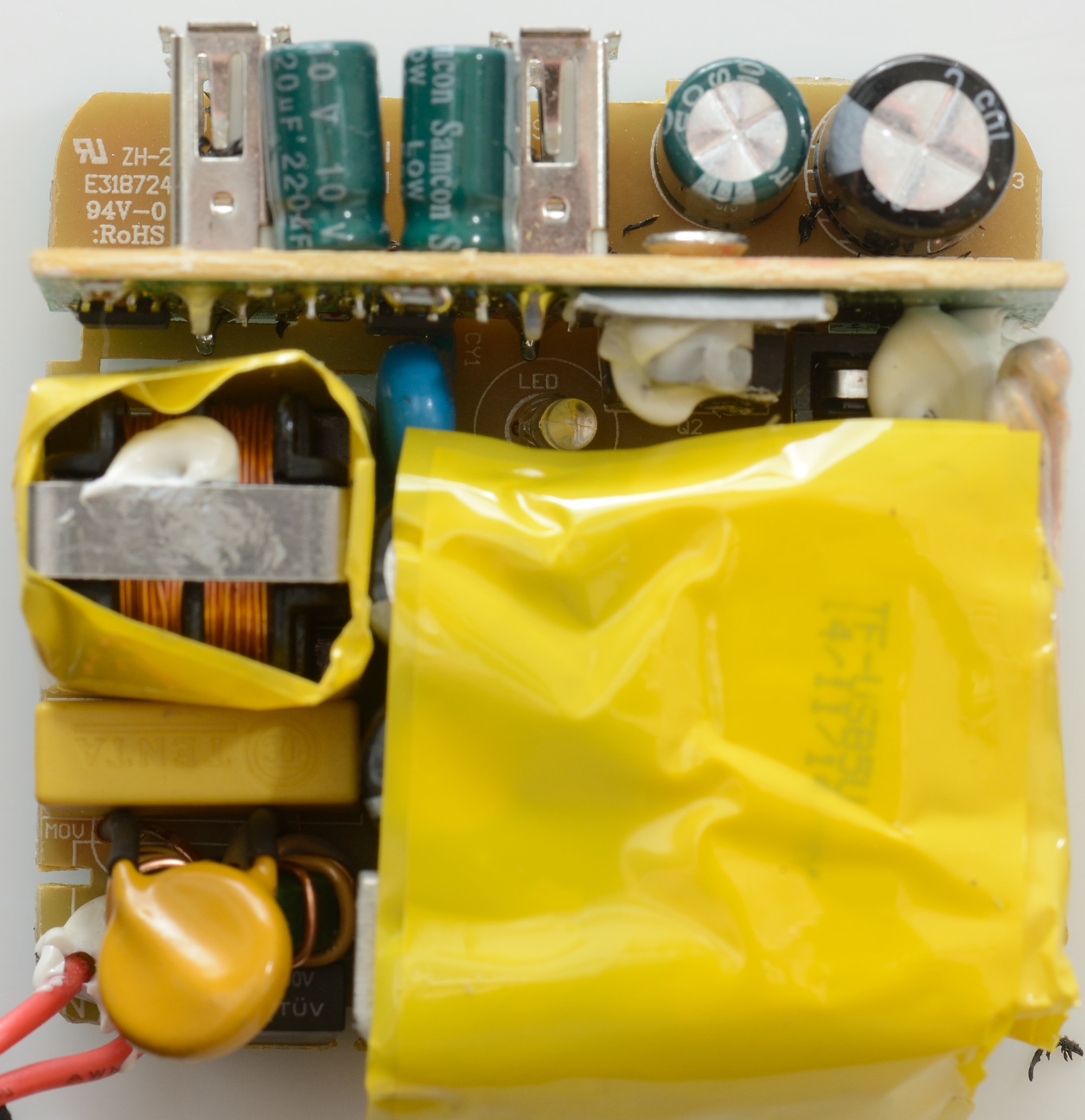
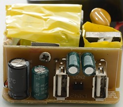
The charger has two circuit boards. The large one has 3 inductors: 2 common mode at the input and one inductor at the output.
At the input where the two red wires are connected there is a MOV. The mains switcher is mounted on a heatsink below the yellow tape and there is a blue safety capacitor.
Notice the led at on the circuit board, the plastic top has a light pipe down to it.
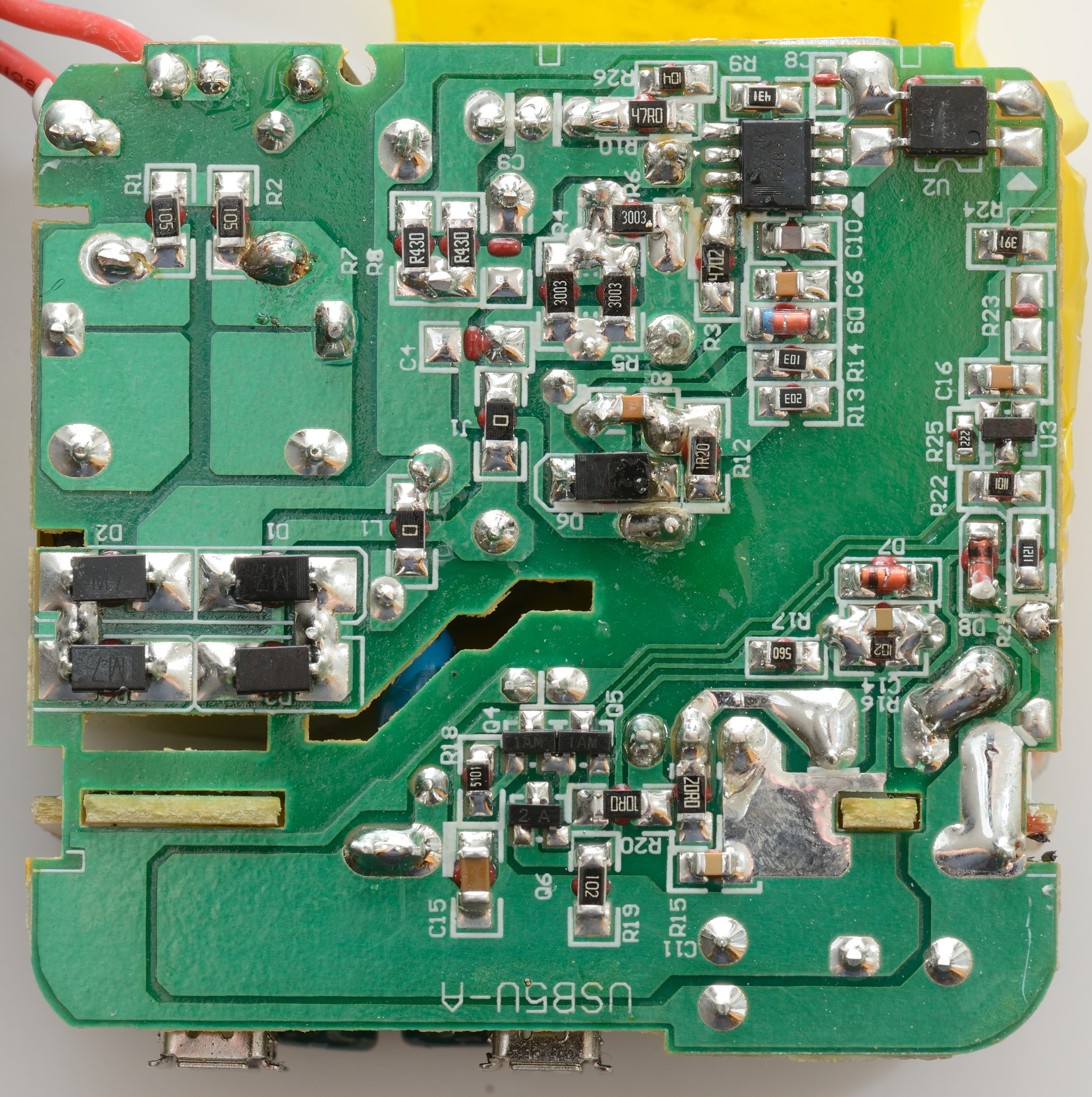
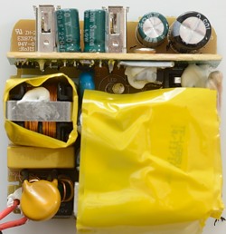
On the input side of the board we have 4 diodes to make a bridge rectifier (D1..D4). The mains switcher (Must be U1), with the optical feedback just besides it (U2). The optical feedback is controlled from U3.
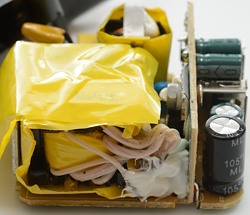
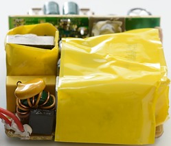
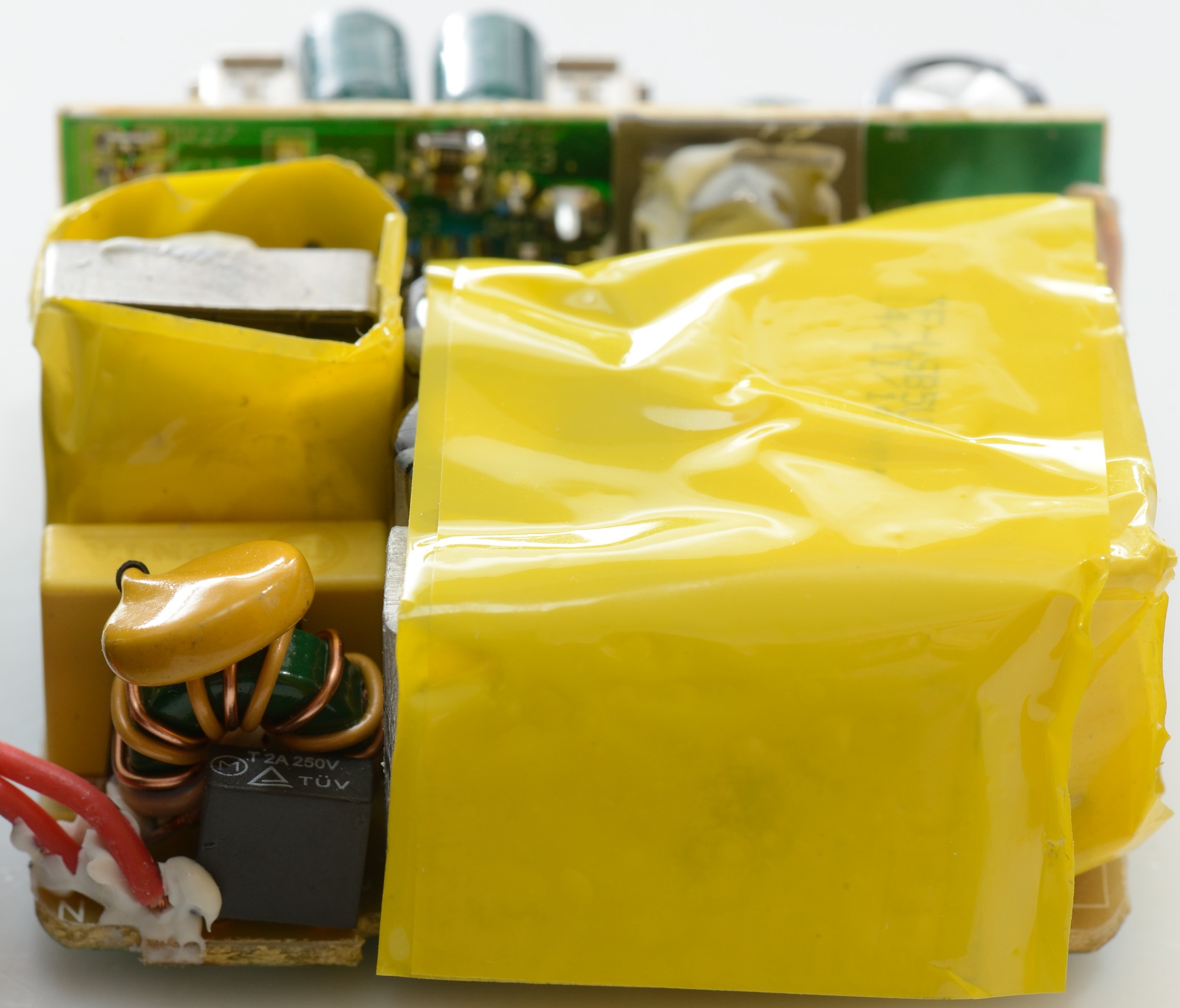
The transformer has a lot of windings, it looks like 3 secondaries. From this side the first input common mode coil is easier to see, just behind a 2A input fuse.


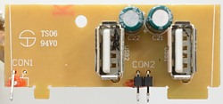
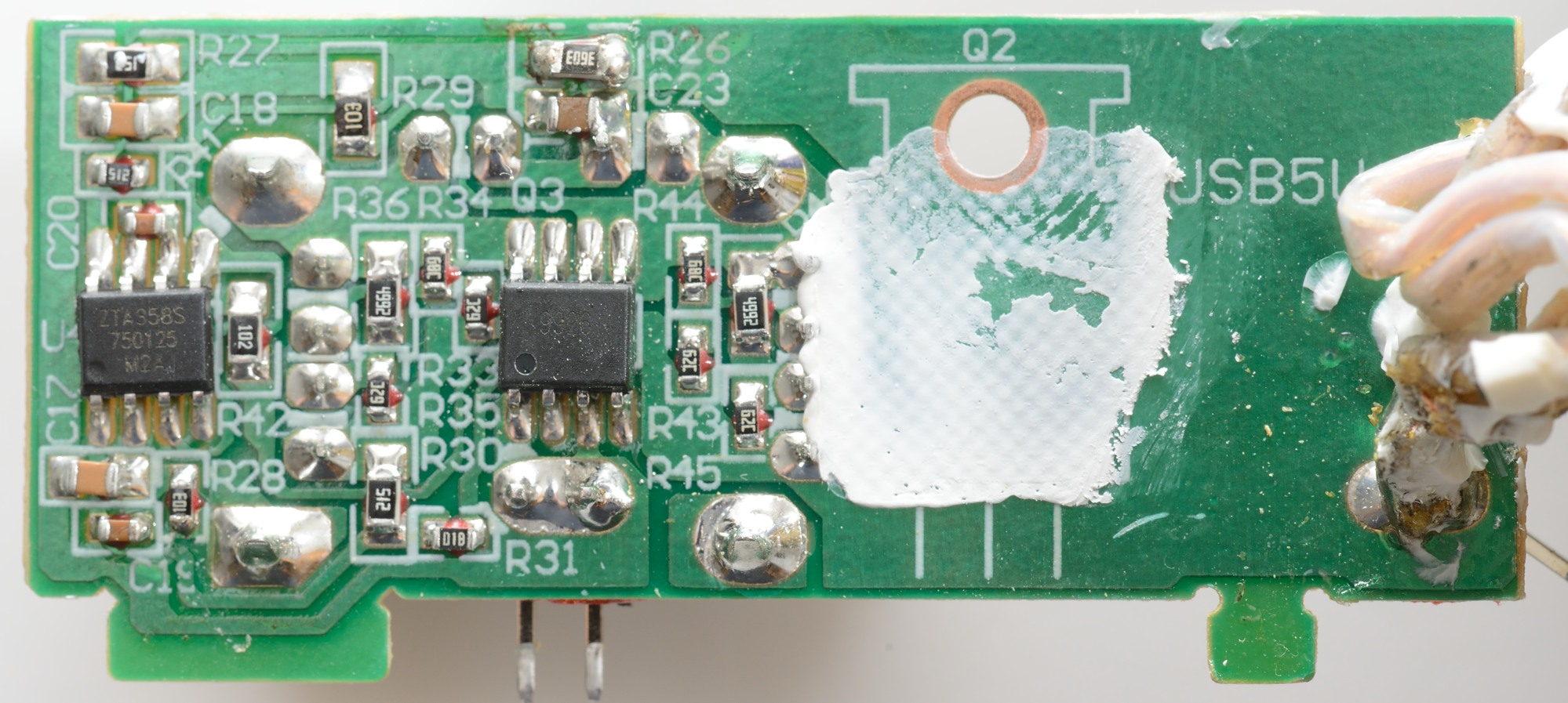
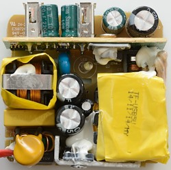
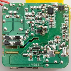
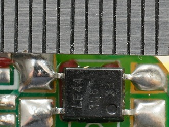
The small circuit board has a lot of parts on it. U4 is a dual opamp used to detect over current, Q3 must be a dual transistor that can turn the output current on and off and Q2 is the rectifier. This circuit board is also used as heatsink and the reason it is enough is because it is synchronous rectification.
I cannot find the current sense resistors, the probably means that current is senses accross Q3.
Only 5.5mm here.
Testing with 2500 volt and 5000 volt between mains and low volt side, did not show any safety problems.
Conclusion
The charger looks fairly well constructed and can deliver a lot of current for a two outputs, but something went wrong in the design and it has more noise than expected in the output.
Notes
Index of all tested USB power supplies/chargers
Read more about how I test USB power supplies/charger