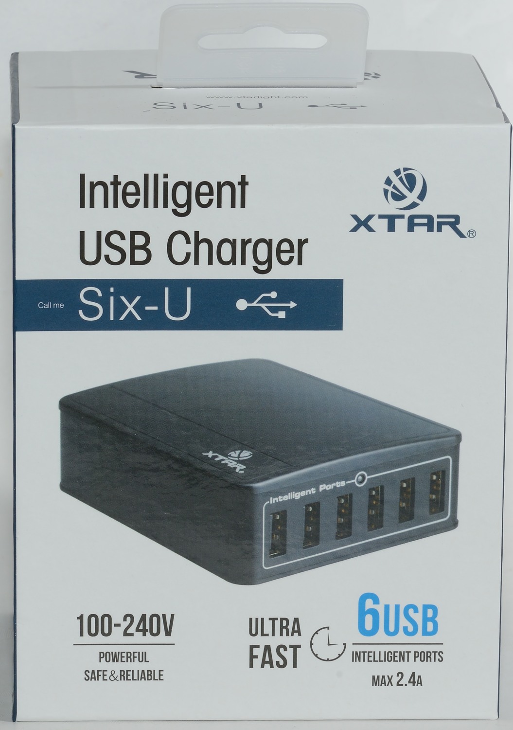
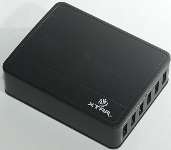
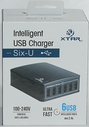
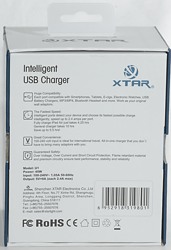
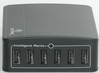
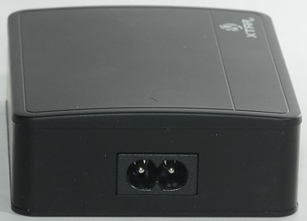
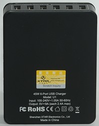
Xtar U1
Official specifications:
- Input: 100-240V~ 1.05A 50-60Hz
- DC Output: 5V / 9A (each port 2.4A max)
- Power: 45W
- Size: 100(L) × 80(W) × 30(H) mm/ 3.9(L) ×3.1(W) × 1.2(H) in
- Weight: 196 g / 6.9 oz
I got it on Aliexpress from: ShenZhen Lighting Star Sci&Tech Co,LTD
I got the charger in a retail box.
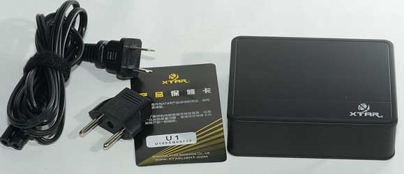
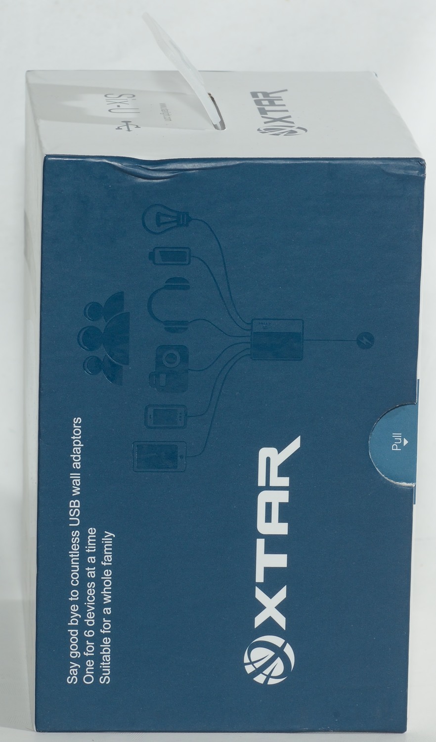
It was supplied with an US cable and a adapter, not exactly a good solution.
Measurements
- Power consumption when idle is 0.14 watt
- The indicator led is blue
- All usb port are with automatic coding with maximum as Apple 2.4A
- All outputs are in parallel.
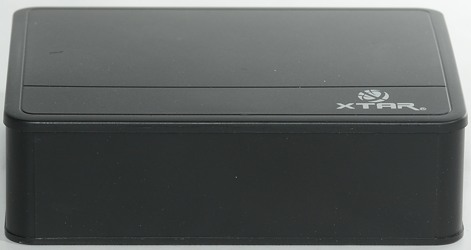
- Size: 100x80x31mm
- Weight 203g
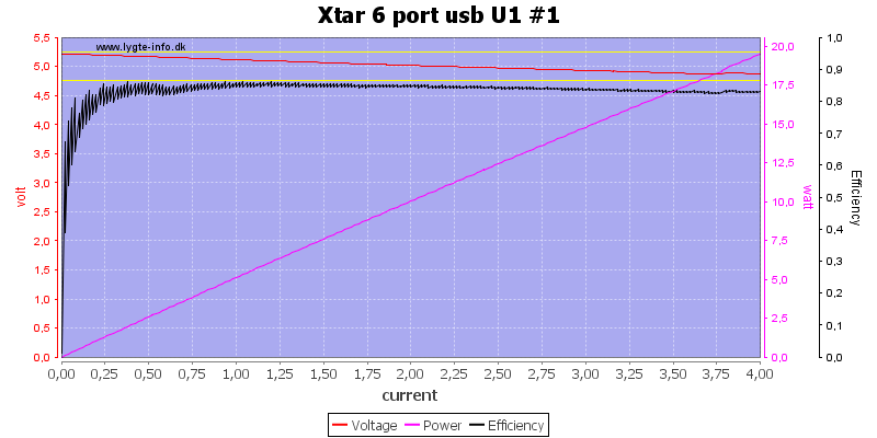
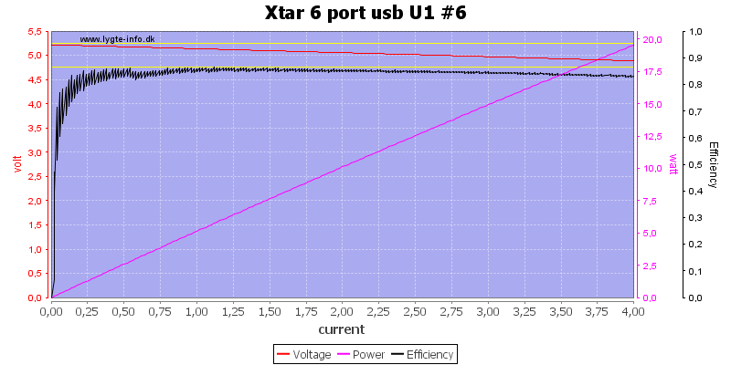
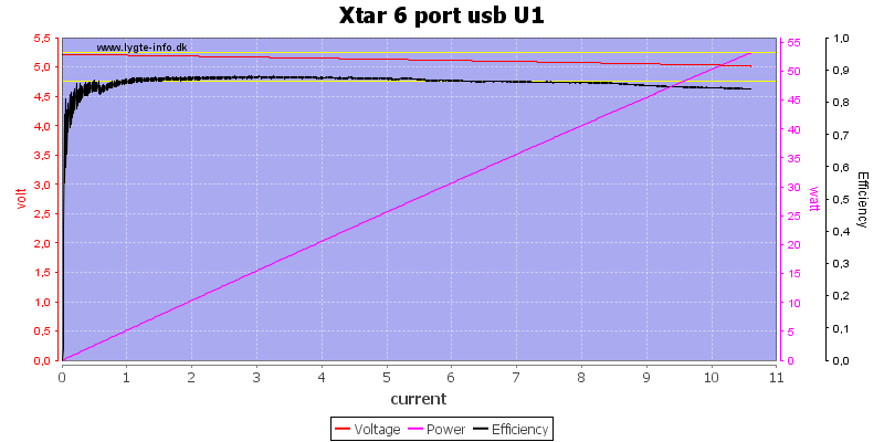
Each port is rated for 2.4A, but there is no individual overload protection. The common overload protection is at about 10.5A, this looks very resonable.
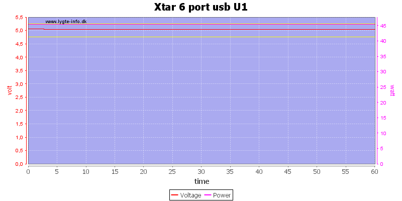
There is no problem running at full 9A load for one hour.
The temperature photos below are taken between 30 minutes and 60 minutes into the one hour test.
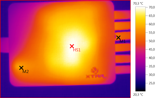
M1: 52,1°C, M2: 57,2°C, HS1: 70,3°C
HS1 is the transformer.
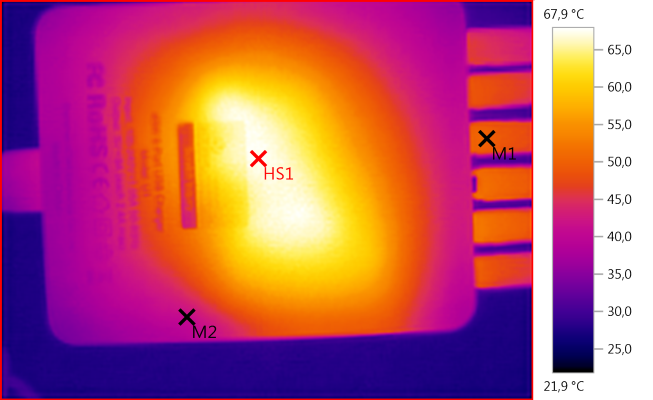
M1: 50,2°C, M2: 41,2°C, HS1: 67,9°C
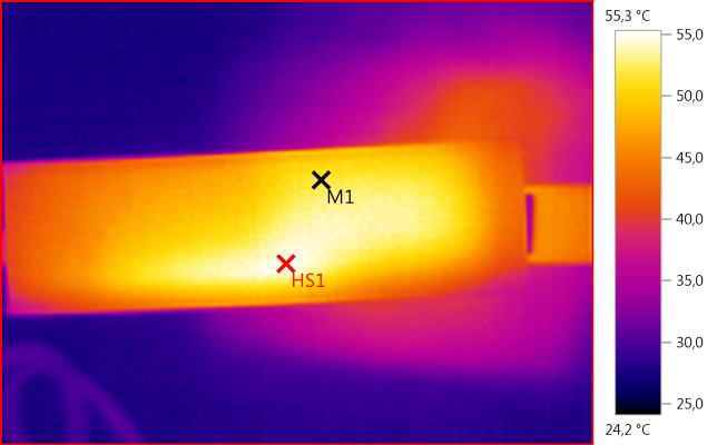
M1: 51,8°C, HS1: 55,3°C
HS1 is the mains switch transistor
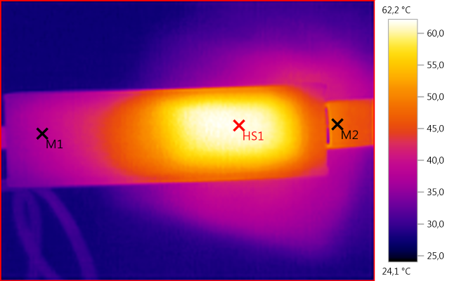
M1: 37,9°C, M2: 48,3°C, HS1: 62,2°C
HS1 is the rectifier.
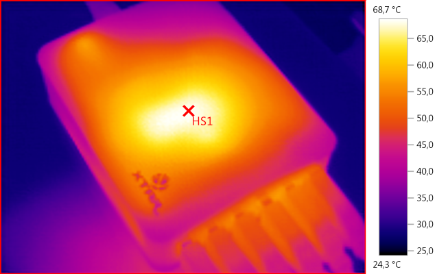
HS1: 68,7°C
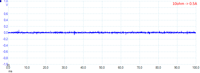
Noise at 0.5A load is: 12mV rms and 200mVpp.
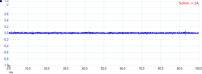
Noise at 1A load is: 13mV rms and 200mVpp.
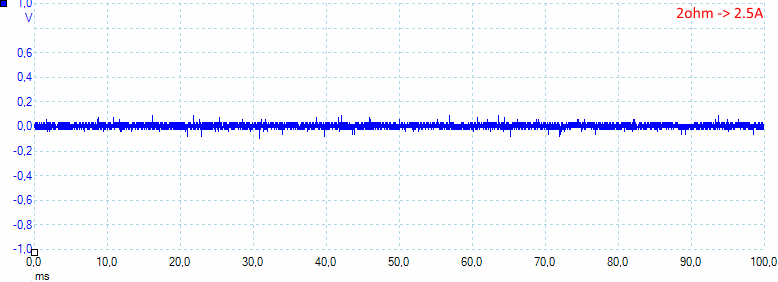
Noise at 2.5A load is: 55mV rms and 400mVpp.
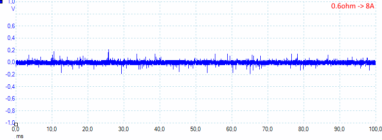
Noise at full load is: 30mV rms and 560mVpp.
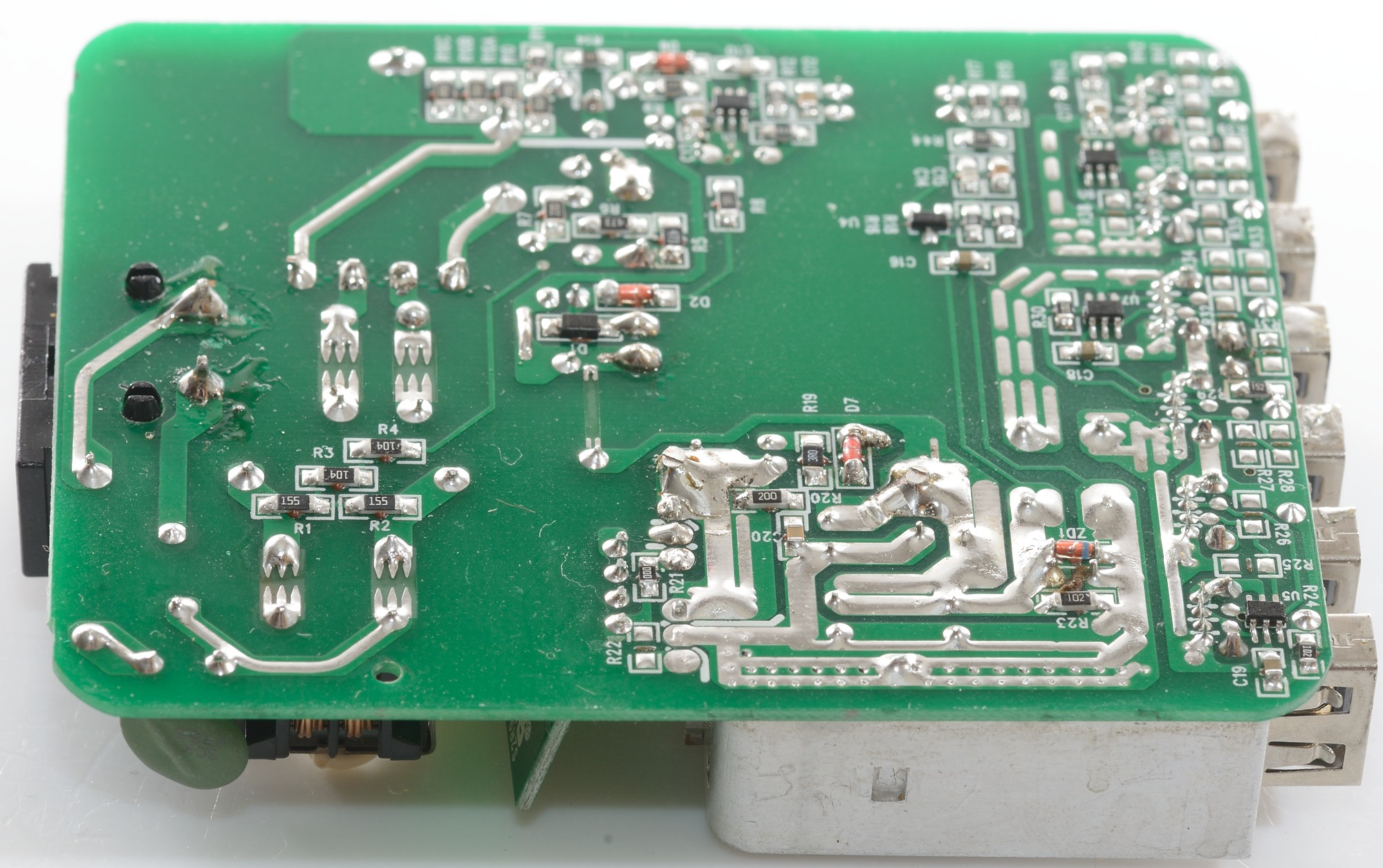
Tear down
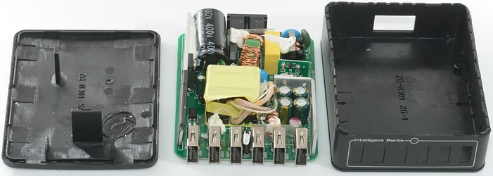
The charger was to big for my vice, but a mallet could easily crack the glue.

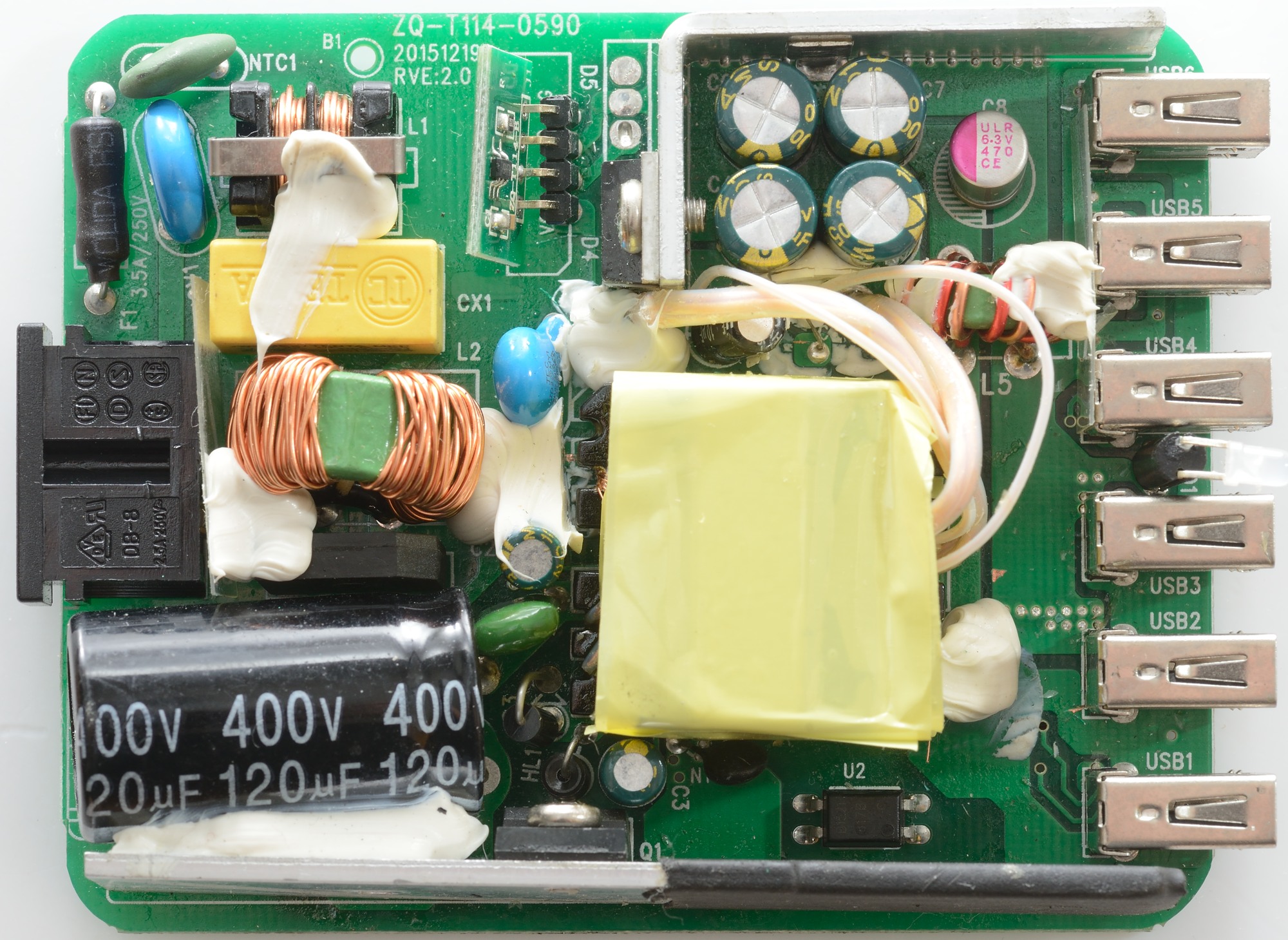
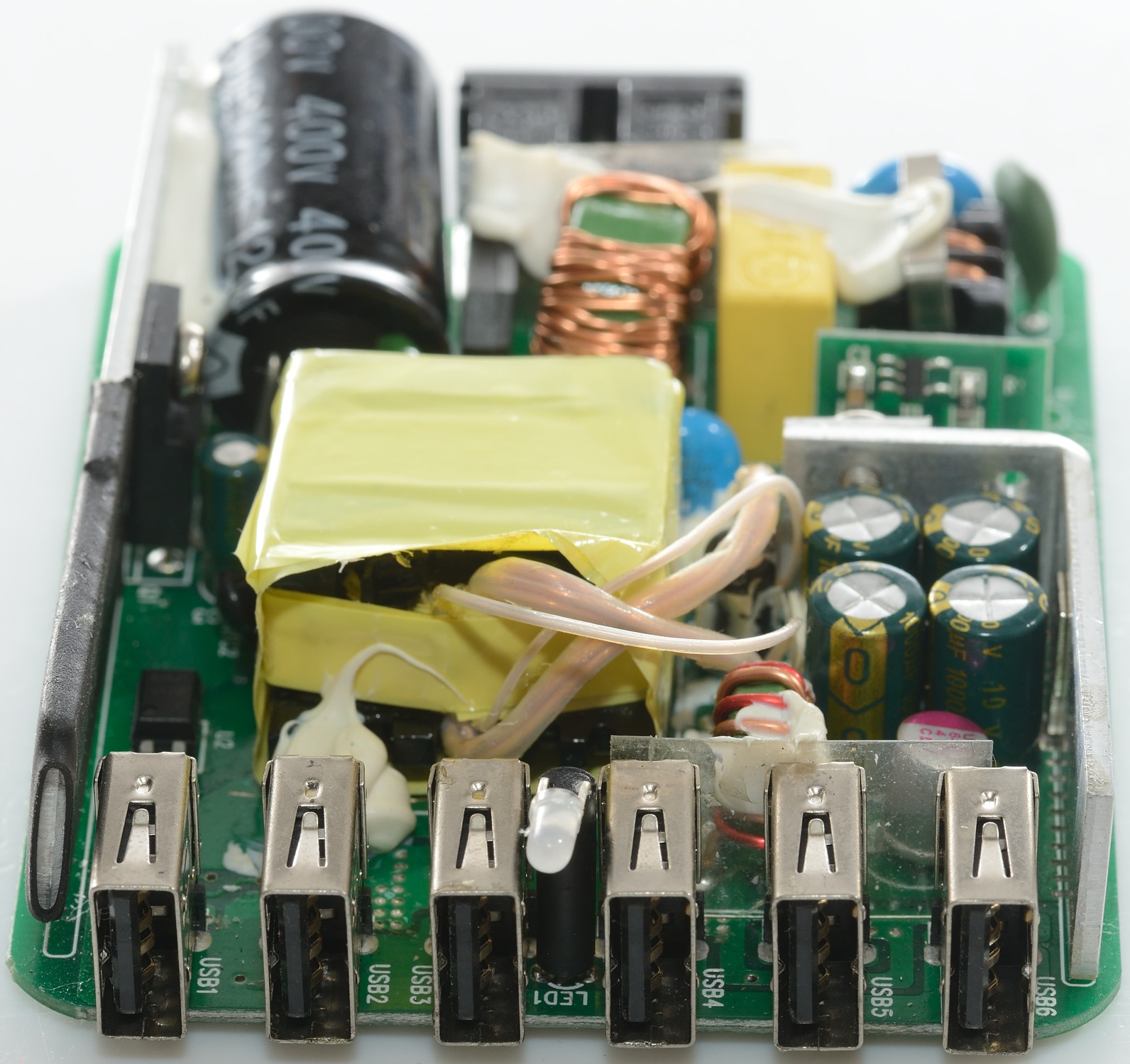
The mains input looks good, it has a fuse, a MOV to handle transients and a NTC to handle inrush current. Then it has two common mode coils with a capacitor between, before the bridge rectifier. The mains switcher transistor is mounted on the long heatsink with isolation covering it at the low side. There is a opto coupler for feedback between the transformer and heatsink. The blue capacitor is the safety capacitor.
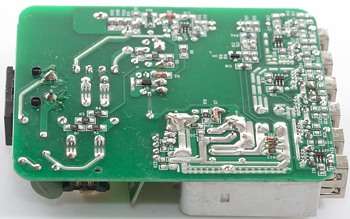
At the low volt side there is a rectifier on a shorter heatsink, this must be a synchronous rectifier with the control circuit on the small circuit board. I.e. D4 is not a diode, but a transistor (At an earlier date the circuit board probably had two diodes in parallel). The output does also have a common mode coil (L5).
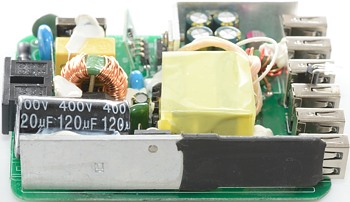
This side is the heatsink for the mains switcher transistor.

The Fuse, MOV and NTC can be seed on the left side of the mains connector.
Between the usb connectors the led can be seen. Notice the extra isolation between the coil and the usb connectors.
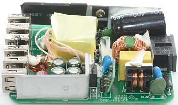
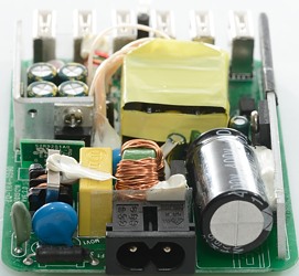
The rectifier heatsink, the small circuit board and one of the common mode coils is on this side.
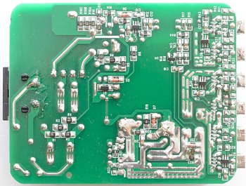
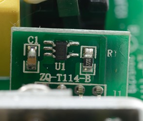
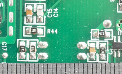
The auto codings IC are here (U5, U6, U7), the switcher controller IC (U1) and the voltage control (U4).
It can also be seen on the circuit board that the small circuit board has a connection to the rectifier transistor, i.e. it is controlling it.
Safety distance is good.
Testing with 2500 volt and 5000 volt between mains and low volt side, did not show any safety problems.
Conclusion
The charger is a good usb charger with a fair amount of power.
Notes
Index of all tested USB power supplies/chargers
Read more about how I test USB power supplies/charger