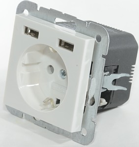
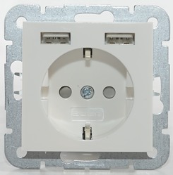
inCharge 2USB Wall Power Outlet
Official specifications:
- No. of outputs: 2
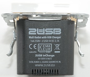
- Output: 5 VDC 2.1A 10.5W
- Maximum voltage: AC 250VAC 50Hz 16A
- Connection wire: Single core, max 2.5mm2
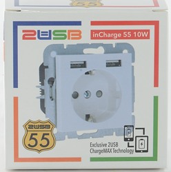


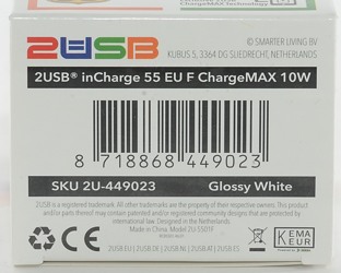
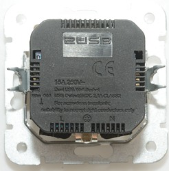
I got it in a cardboard box with specification on it.
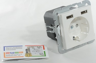
The box included the socket and a instruction sheet with mounting instruction.
Measurements
- Power consumption when idle is 0.15 watt
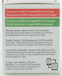
- USB output is auto coding with Apple 2.1A as maximum.
- The two output ports are in parallel.
- Earth is not connected to usb shield
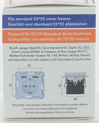
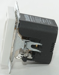
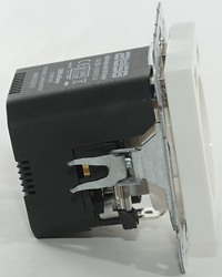
- Need 48mm deep hole.
- Extend 11mm out.
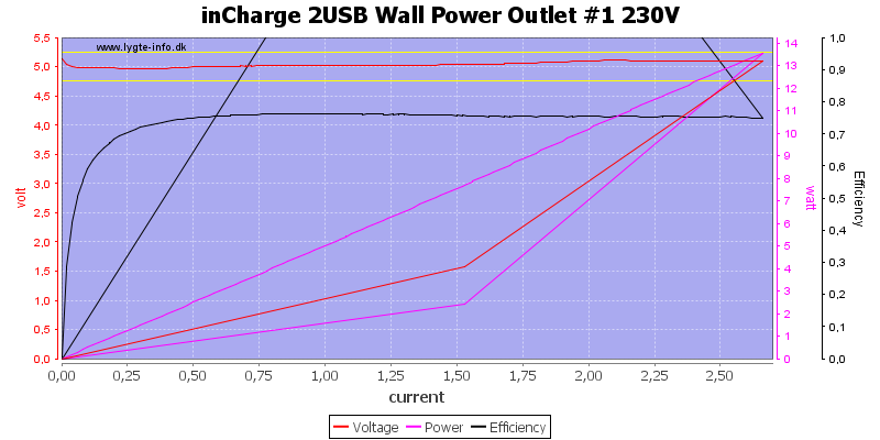
It can deliver about 2.6A on one output.
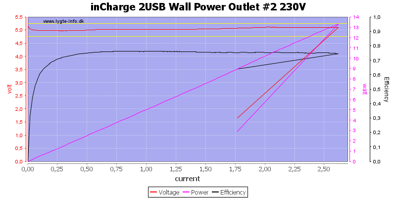
And also on the other output.
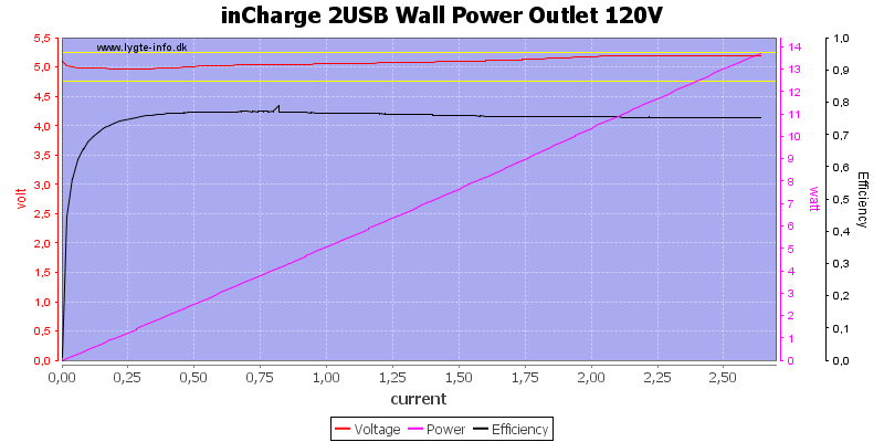
Running two in parallel will still deliver 2.6A, here at 120VAC
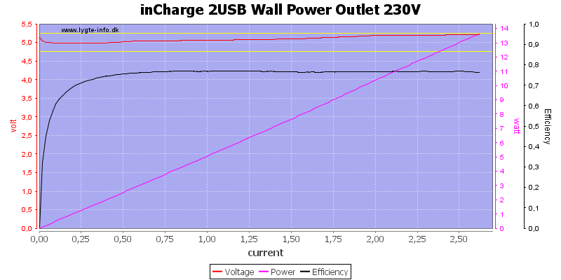
And here at 230VAC.
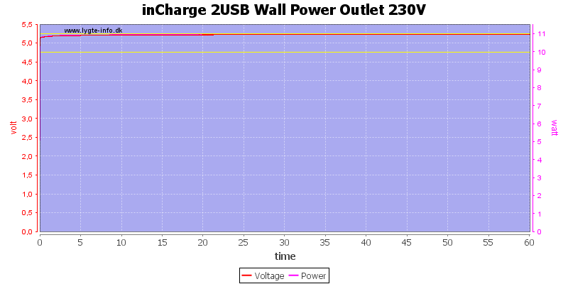
Running one hour at rated load is no problem.
The temperature photos below are taken between 30 minutes and 60 minutes into the one hour test.
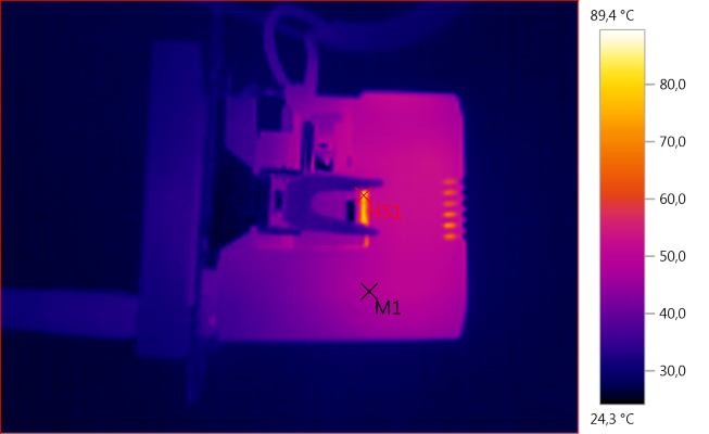
M1: 48,3°C, HS1: 89,4°C
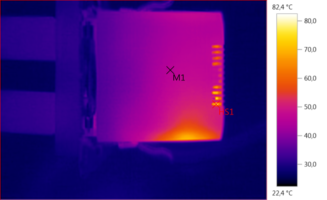
M1: 45,5°C, HS1: 82,4°C
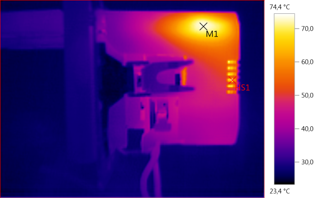
M1: 73,1°C, HS1: 74,4°C
HS1 is the mains switcher or some of the surrounding parts. M1 is the rectifier diode.
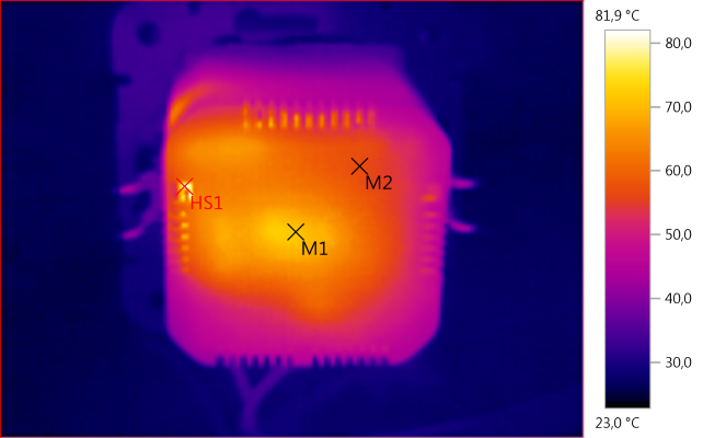
M1: 71,6°C, M2: 56,9°C, HS1: 81,9°C
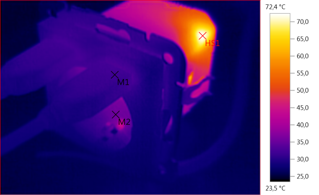
M1: 32,0°C, M2: 35,5°C, HS1: 72,4°C
HS1 is the rectifier diode.
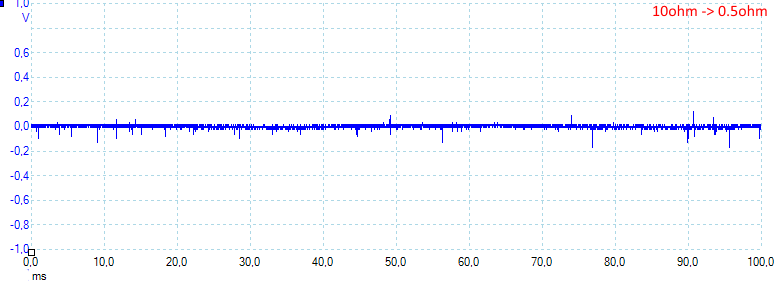
Noise at 0.5A load is: 14mV rms and 309mVpp
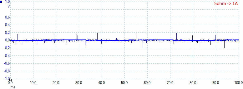
Noise at 1A load is: 12mV rms and 476mVpp.
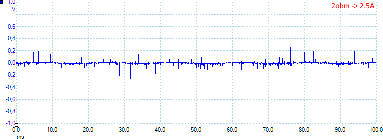
Noise at 2.5A load is: 19mV rms and 648mVpp.
Tear down
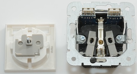
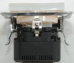
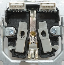
One screw removed the frontplate, this is required for mounting the socket and for connecting the earth wire, note that the mains carrying parts are partial isolated (nice).
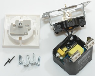
Four screws later and the back is open.
The supply wires for the usb circuit is soldered to the outlet and has an extra layer of isolation.
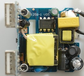
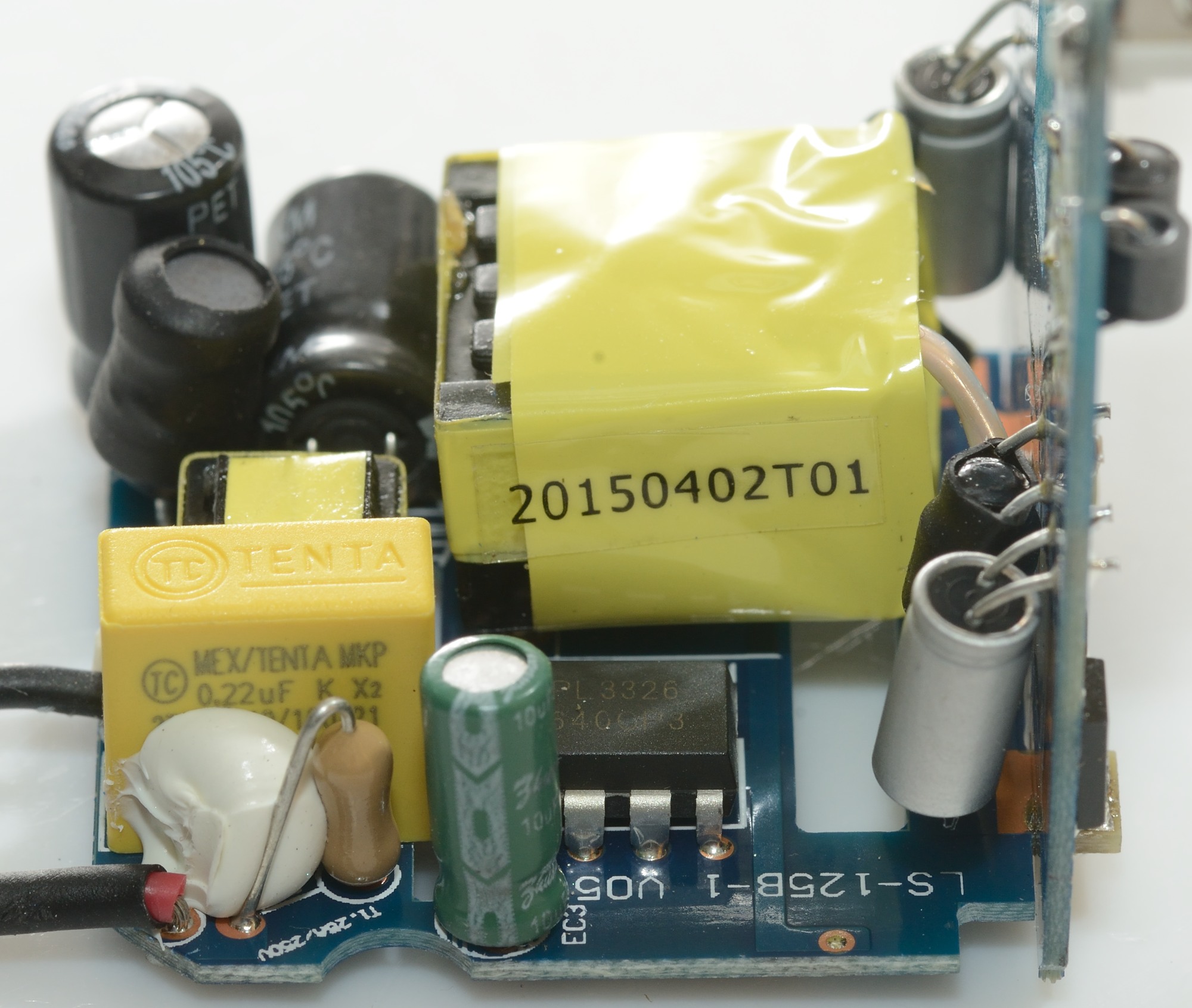
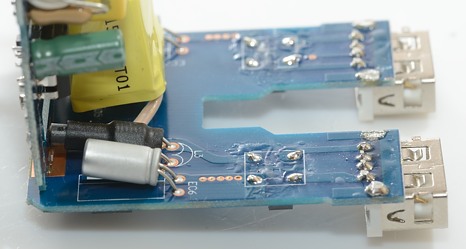
At the mains input is a fuse, there is also a common mode coil and a inductor. The mains switcher is a PL3326. Beside the transformer is a safety capacitor.
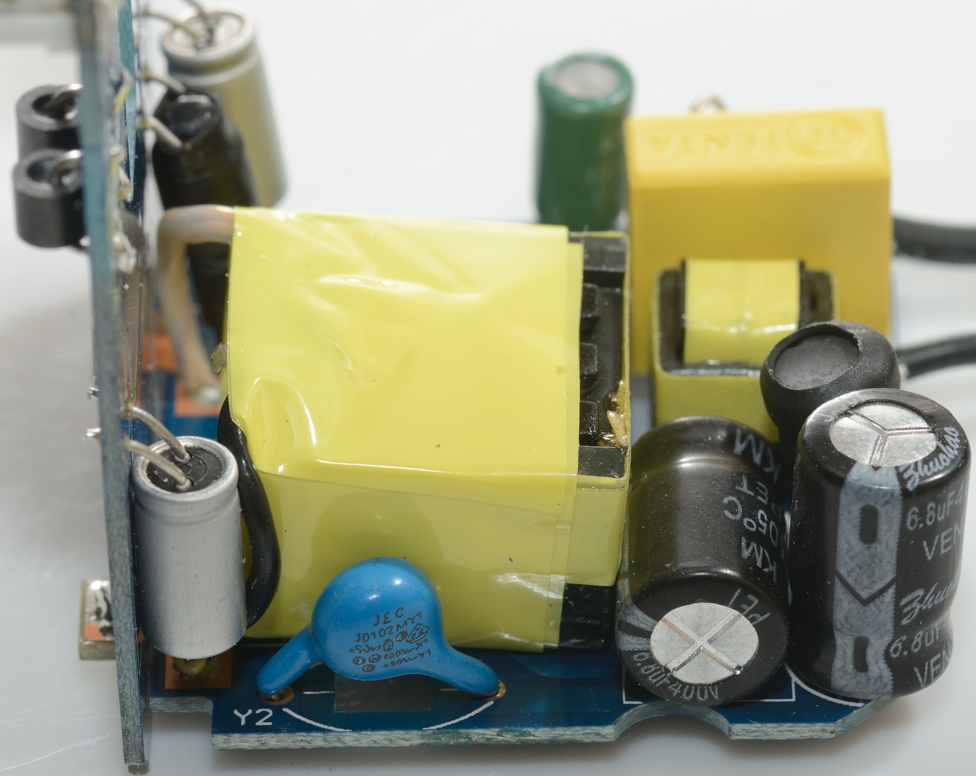
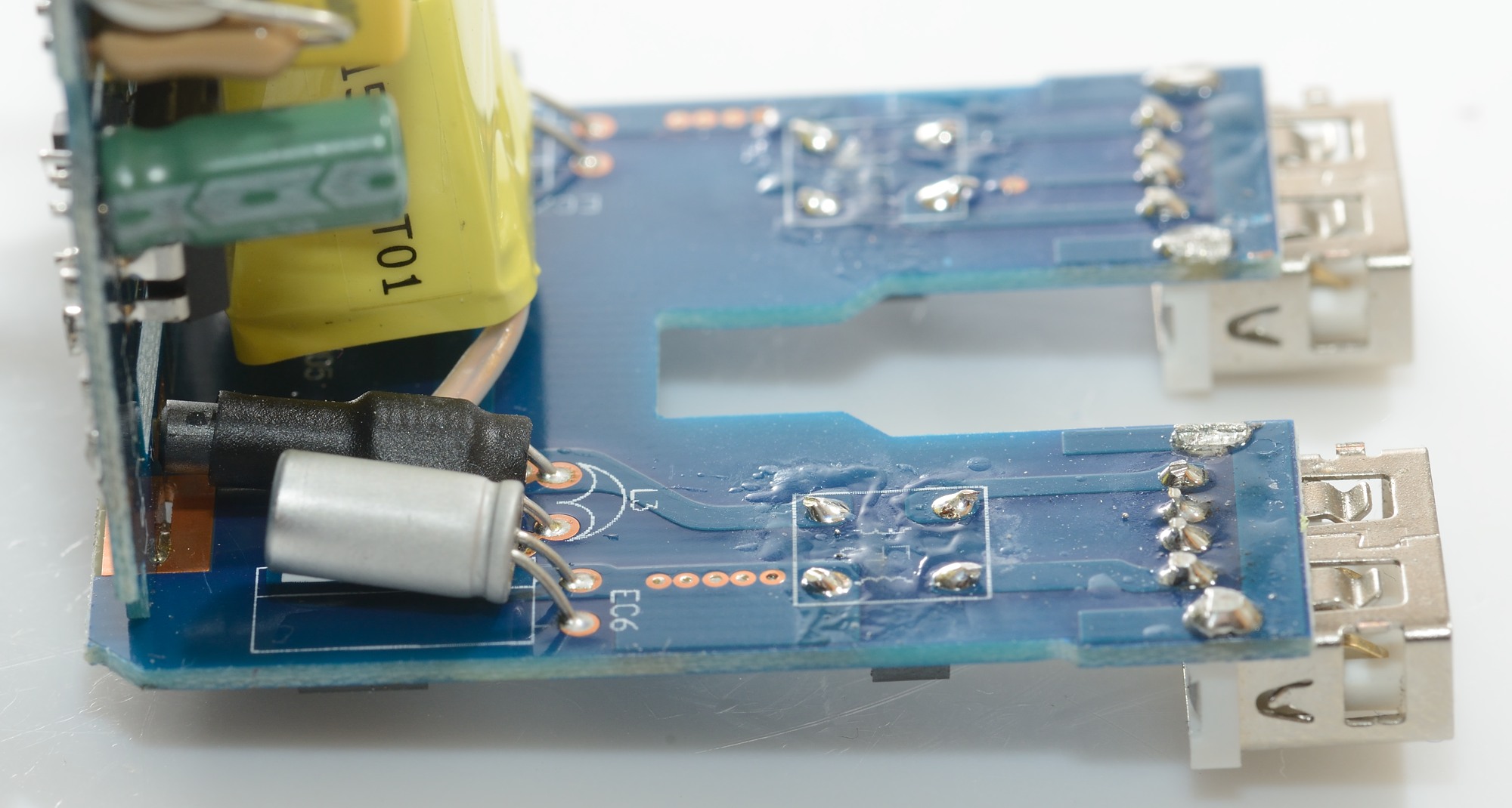
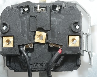
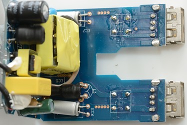
The low volt side of the transfor uses flying leads, they are connection to the circuit board, but all the electronic for the low volt side is on the other circuit board.
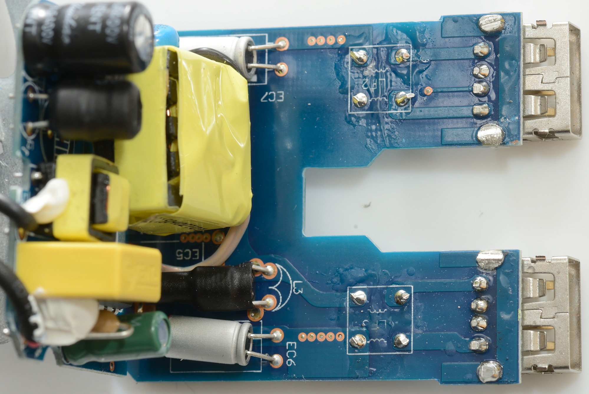
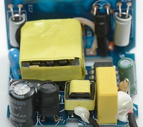
The circuit board with the low volt electronic has two capacitors and a inductor on this side.

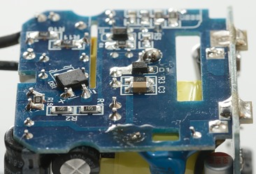
On the first image the fuse (T1) can be seen, there is also the switcher IC. The second image shows the inductor (L2) and the common mode coil.

On this side the safety capacitor (Y2) with all its approval markings can be seen.
There is some black isolation paper between the transformer and the metal can of a capacitor (nice).
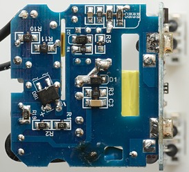
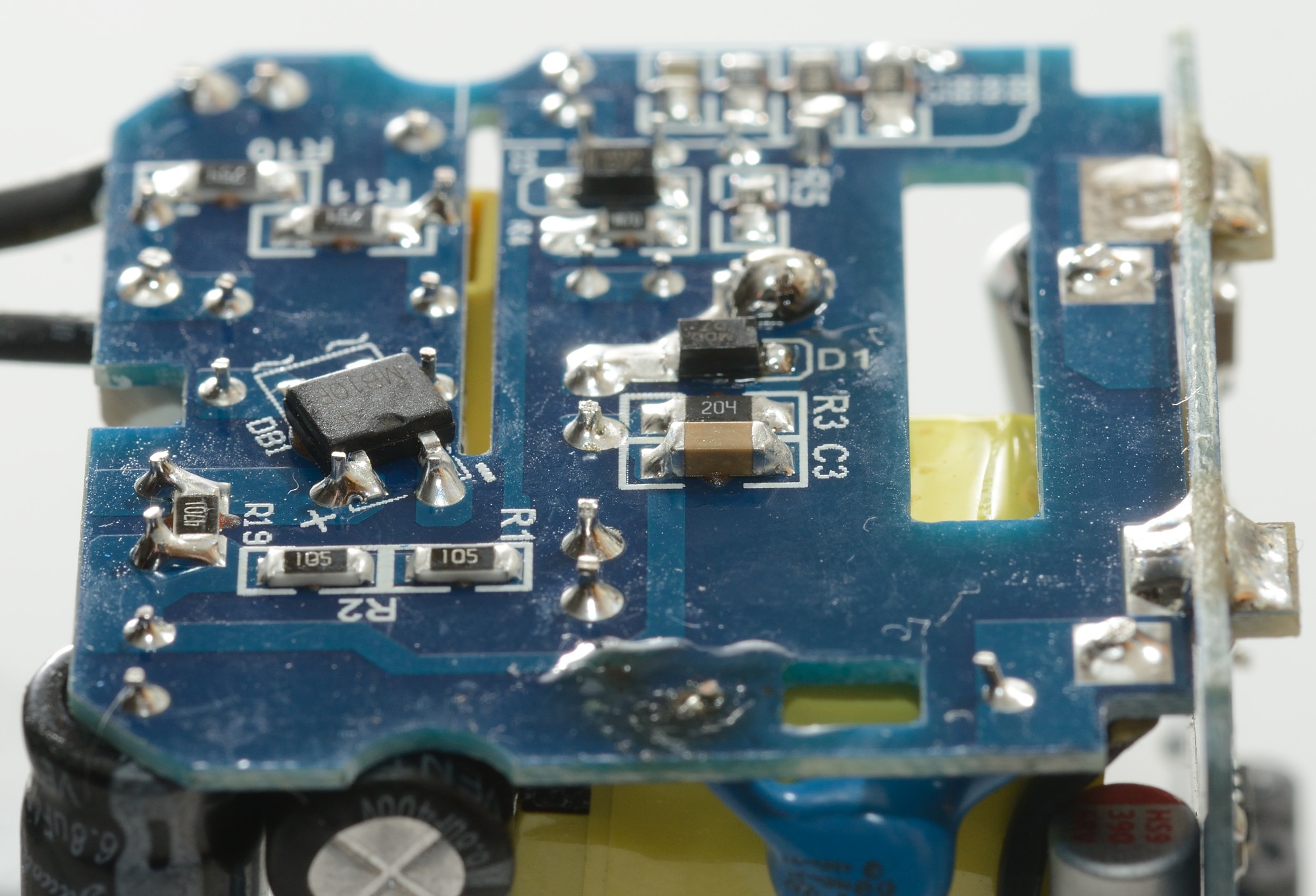
On the other side of the mains input circuit board is the bridge rectifier (DB1).
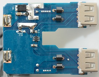
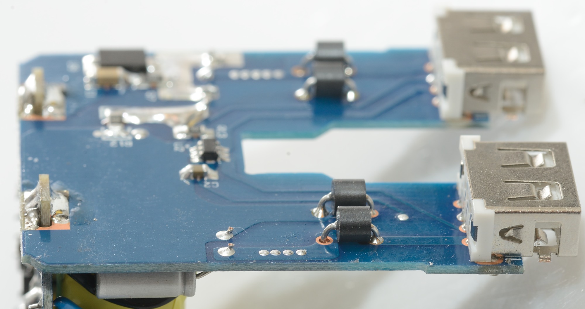
The low volt circuit board has a rectifier diode (D9), a dual auto coding IC (U2) and some ferrite beads to reduce noise.

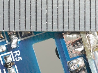
The circuit board has large slots to improve safety, the actual distance is about 6mm between mains and low volt side.
Testing with 2830 volt and 4242 volt between mains and low volt side, did not show any safety problems.
Conclusion
The construction, output current, coding and safety looks fine. I could have wished for slightly lower idle power.
I will rate this as a good mains output and usb charger.
Notes
Index of all tested USB power supplies/chargers
Read more about how I test USB power supplies/charger
How does a usb charger work?