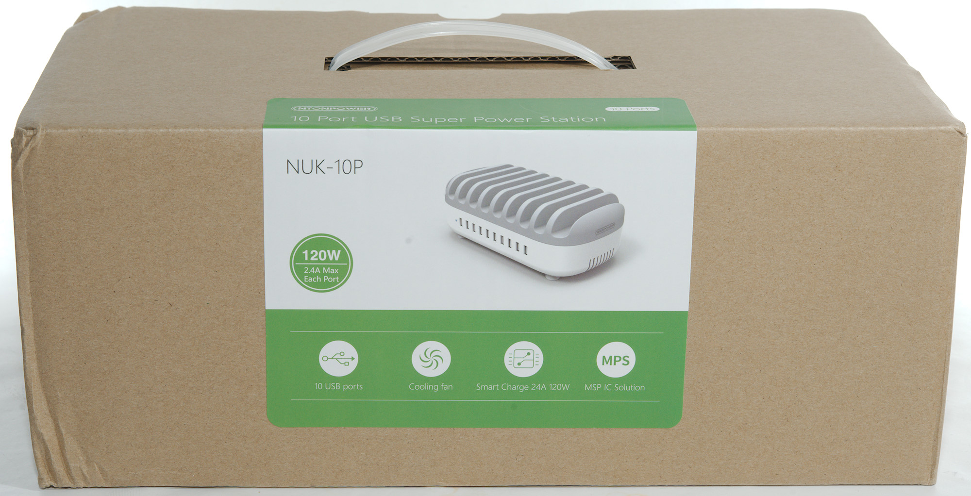
10 port usb charger Ntonpower NUK-10P
Official specifications:
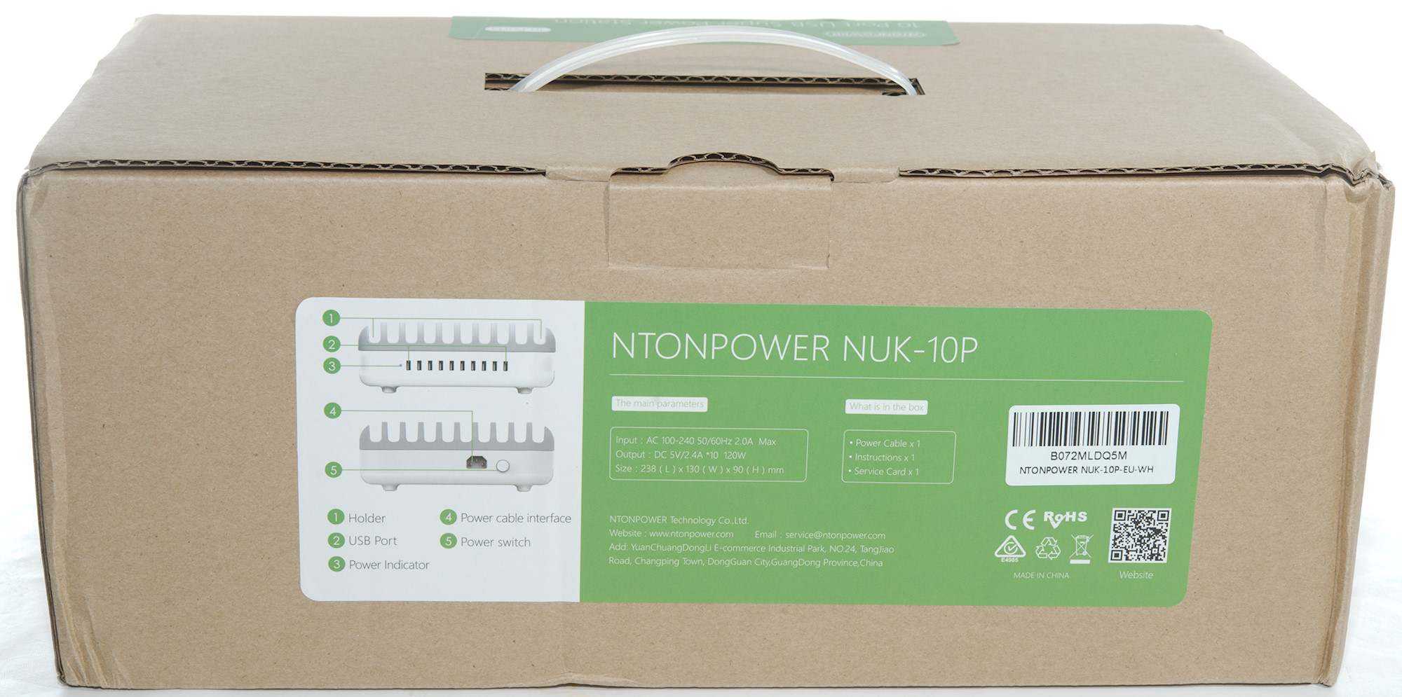
- Dimension: 238 x 130 x 98 mm
- Input: 100-240VAC 50/60Hz 2A max.
- Material: Aluminum Alloy + ABS
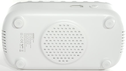
- Heat Dissipation: Cooling Fan Ventilation Holes
- Total Output: 5V 2.4A*10 120W
- Each Port Output: 5V2.4A max
- Charging: Smart IC+Synchronous Rectification+Current Limit+Wide Voltage
- Features: 10 Stands for Phones/Tablets
I got it from Ntonpower

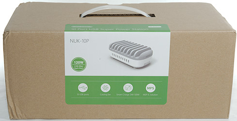
I got it in a card board box.
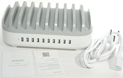
It contained the charger, a mains cable and a instruction sheet.
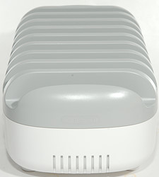
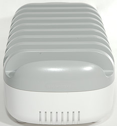
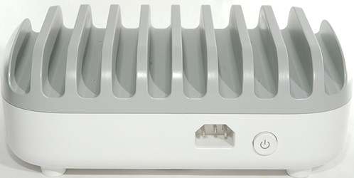
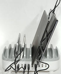
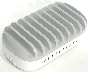
The top works for both phones and tablets.
Measurements
- Power consumption when idle is 0.07 watt
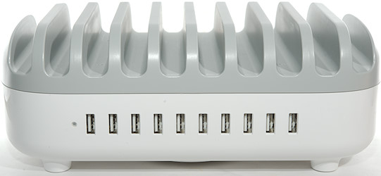
- All usb outputs are auto coding with Apple 2.4A as maximum.
- All outputs are in parallel, but with individual port protection.
- The fan only starts when the charger is warm and it is not that loud.
- Weight: 810g
- Size: 238 x 130 x 90mm
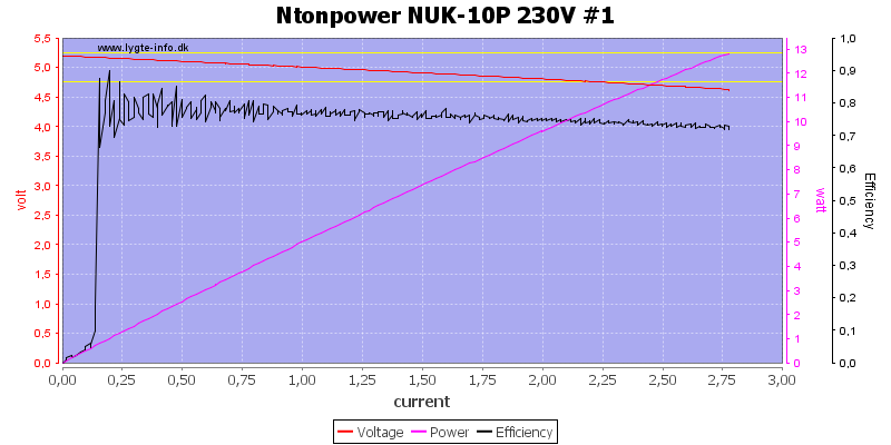
The output can deliver about 2.7A before the overload protection kicks in, this is fine.
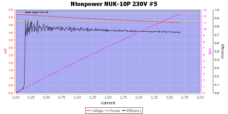
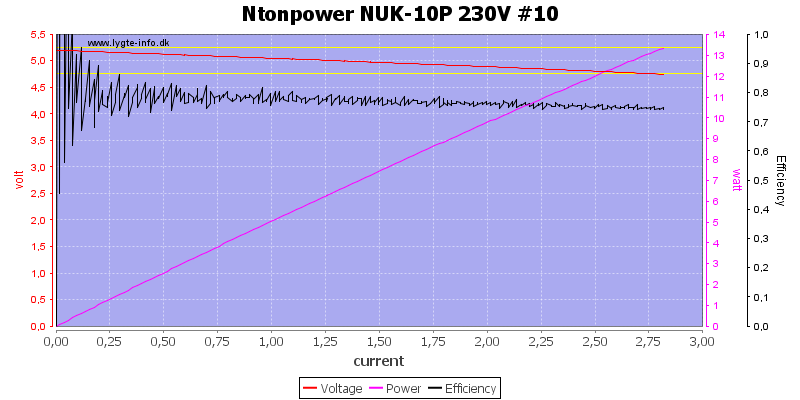
The current limit varies slightly between the outputs.
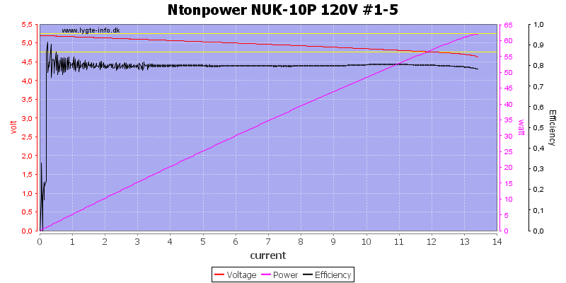
The charger works fine on 120VAC, here I test 5 ports at once.
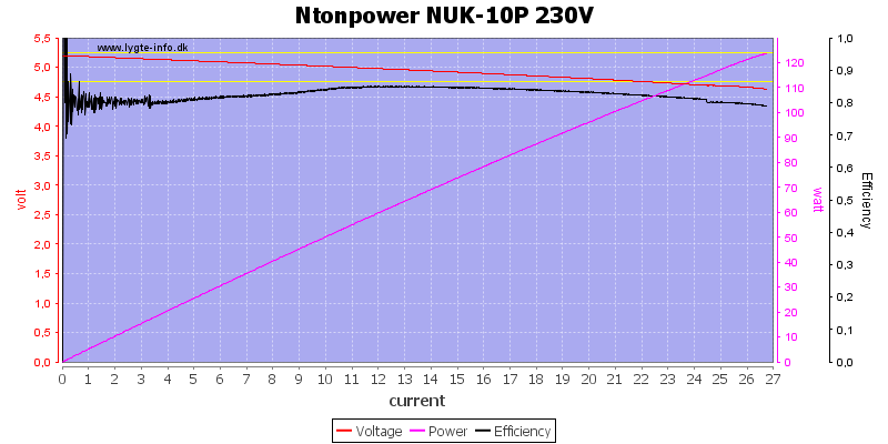
And all 10 ports, it goes up to about 27A before protection trips.
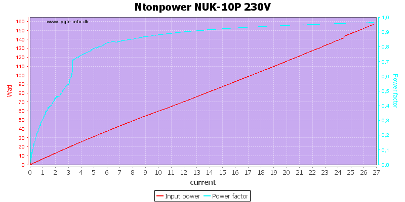
The circuit inside is not a common switcher, there is some more, this can be seen from the Power Factor (PF). Small power supplies has a PF below 0.5, but here it is about 0.95, this means it has an extra circuit to correct PF (The ideal PF is 1).
More about this in the tear down.
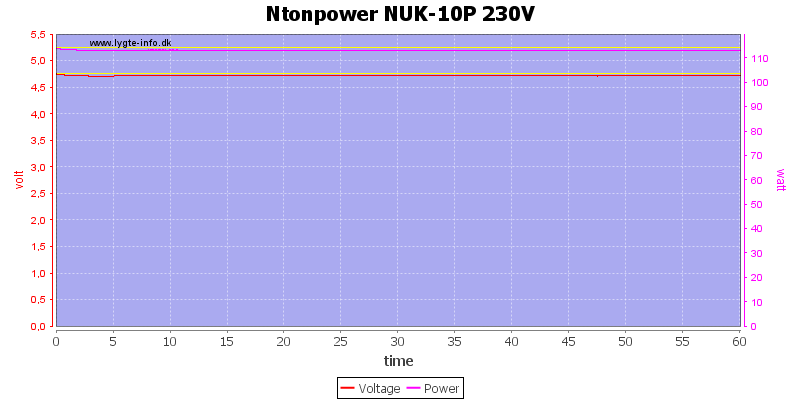
No problems running one hour at 24A.
The temperature photos below are taken between 30 minutes and 60 minutes into the one hour test.
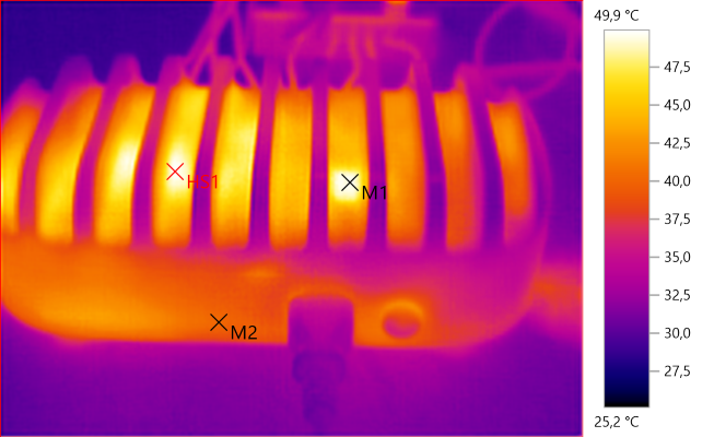
M1: 49,7°C, M2: 40,3°C, HS1: 49,9°C
HS1 must be the transformer. M1 is the square pad on top of the PFC heat sink.
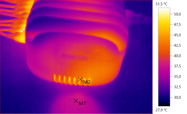
M1: 37,8°C, M2: 45,6°C, HS1: 51,5°C
The exhaust air is not very warm.
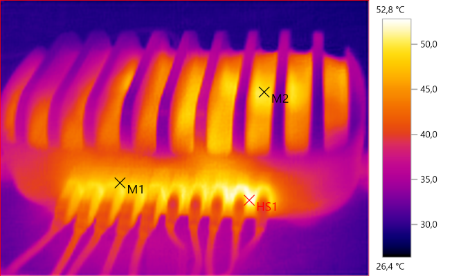
M1: 48,2°C, M2: 49,4°C, HS1: 52,8°C
The connectors is a bit warm, it is probably due to the individual port protection chips.
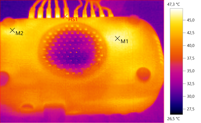
M1: 46,2°C, M2: 45,3°C, HS1: 47,3°C
There is some hot spots on the bottom, but the fan mostly keeps it a uniform temperature.
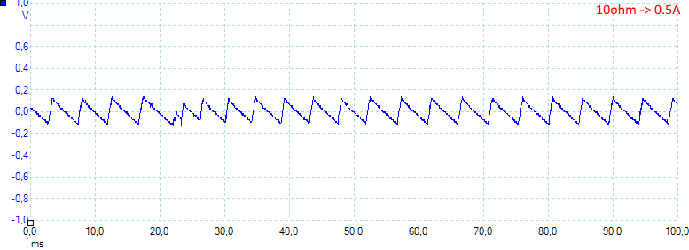
At 0.5A the noise is 67mV rms and 348mVpp.
It looks like the regulation has some ripple at low current.
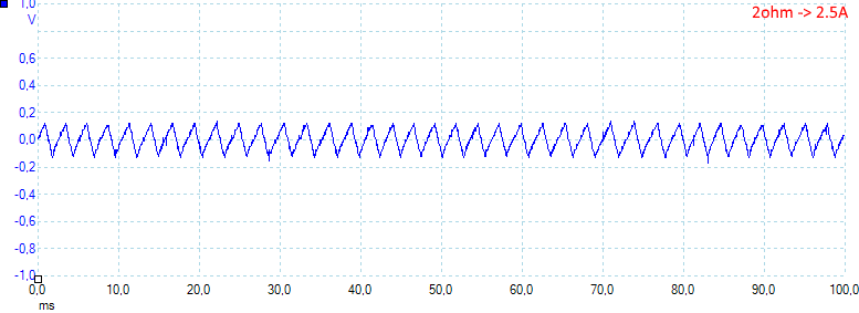
At 2.5A the noise is 70mV rms and 370mVpp.
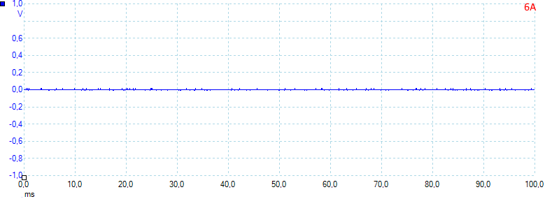
At 6A the noise is 2mV rms and 58mVpp, this is low noise.
The regulation "noise" disappears around 4A load.
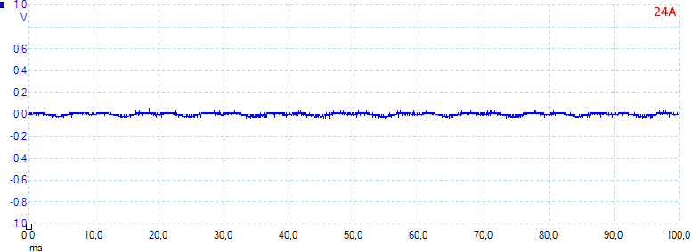
At 24A the noise is 10mV rms and 76mVpp.
Tear down
The screws where under the feet, but they where triwings.
A shade over the led indicator, a bit primitive.
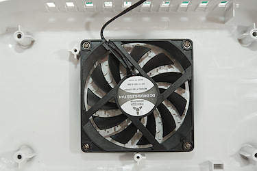
The fan. It only run when necessary and is fairly low in noise.
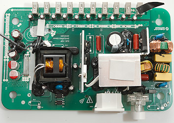
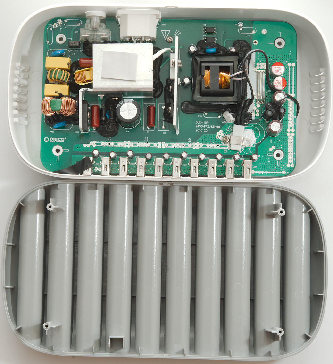
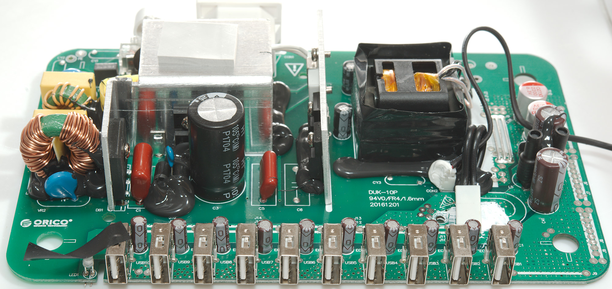
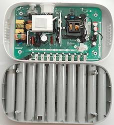
There is a lot of stuff in this charger. I will start at the mains input where two white wires goes to a thermo switch on a heatsink. After the two white wires is a in-rush current limiter (NTC resistor) and a fuse. Then we have the noise filtering with 3 common mode coils, two overvoltage clamps (VR1 & VR2: MOV's) and the bridge rectifier on the heatsink.
The output from the bridge rectifier do not go directly to the big capacitors, but through an inductor (Below the heatsink) and some extra diodes and with a transistor for controlling it. Transistor is on the heatsink next to the capacitor, the diodes are mounted on the circuit board. This circuit is the Power Factor correction (PFC).
The switcher is a resonant converter, it has two transistors (On the straight heatsink), a capacitor (C5) and a transformer. There is a safety capacitor and two opto couplers (U3 & U4) for feedback.
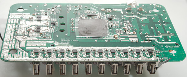
On the output side there is also two inductors (L5 & L6). The power tracks to all the usb outputs is wide and on both sides of the circuit boards.
The "loose" white part with two black wires is a 65°C thermo switch to control the fan, it is clamped to the circuit board with a screw.
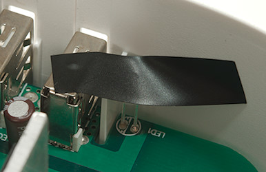
All the black stuff is used to secure the parts stay in place, even if the charger is dropped.

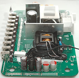
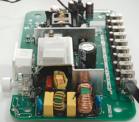
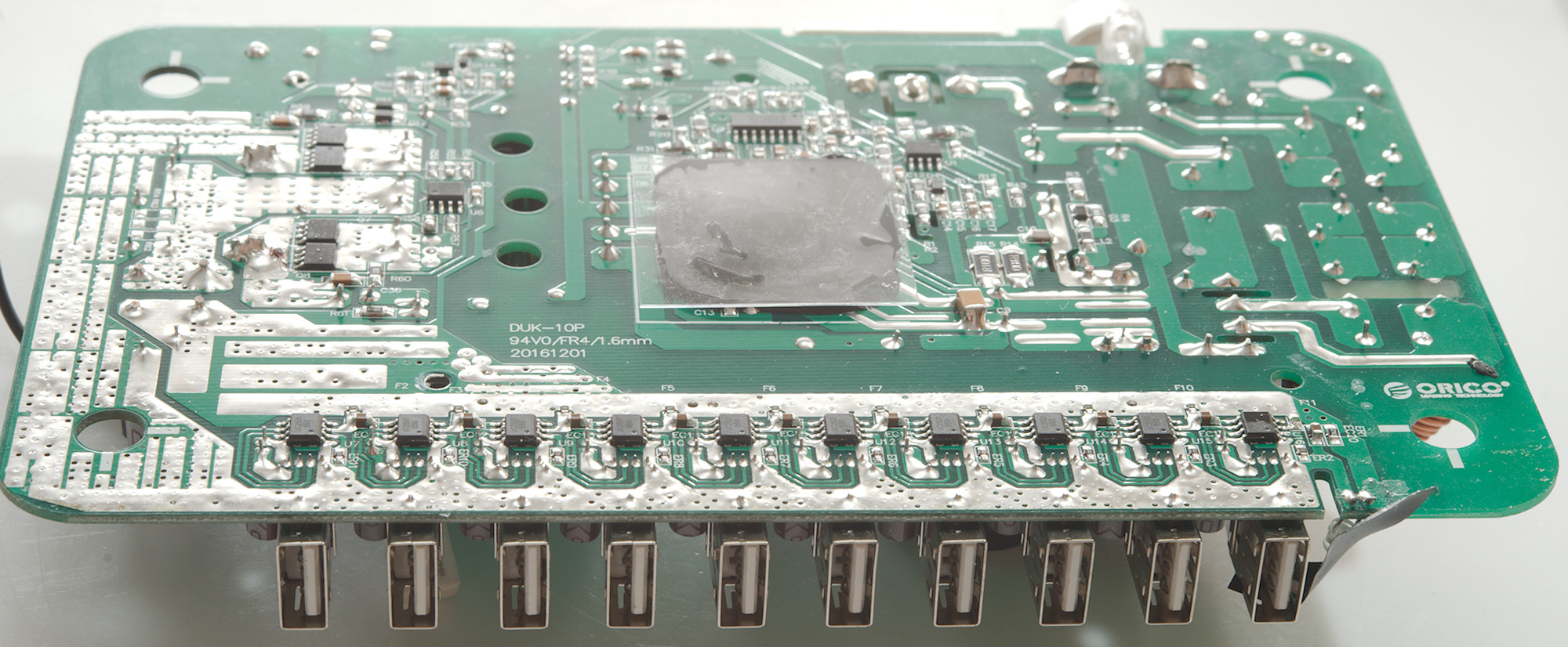
On the first image the two inductors (L5 & L6) is in front. The second image shows all the input filtering
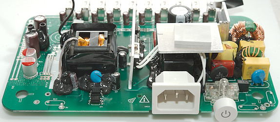
Behind the mains input the black PFC inductor can be seen. The lid has a pin down that presses on the power input connector, to secure it stays in the rails.
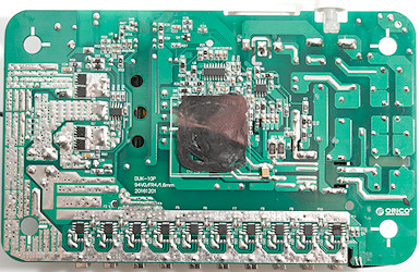
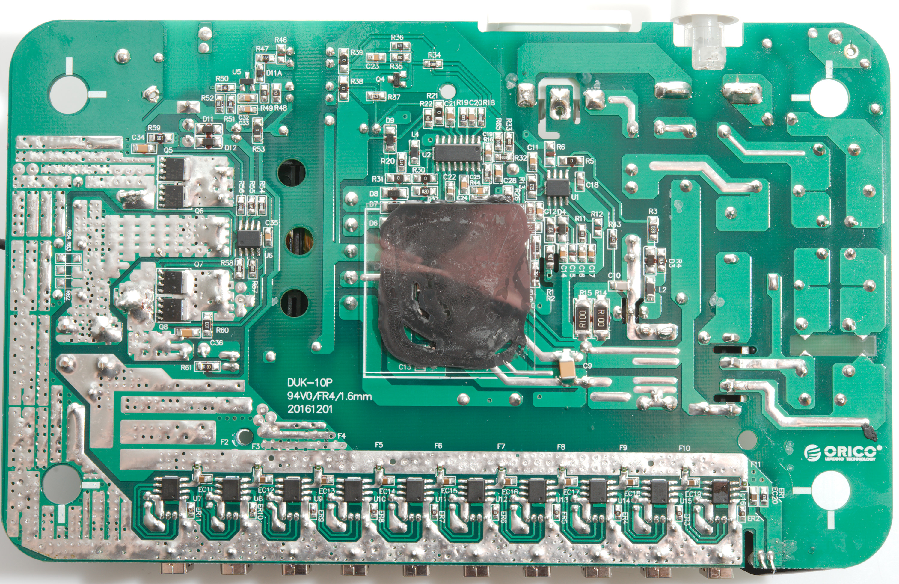
All the chips are on this side. The covered area is not to hide anything, but to improve isolation between the fan and mains voltage (The fan is connected to 5V and must be fully isolated from mains).
The first chip is the Power Factor Correction (U1: TEA19162). Next is the resonant controller (U2: TEA19161T).
On the low volt side is the dual synchronous rectifier controller (U6: TEA1995T) that controls four SMD power transistors (Q5, Q6, Q7, Q8: PSMN1R5-30YLC each: 1.55mOhm 100A).
Near the opto couplers (on the other side) are the usual reference (U5: 431).
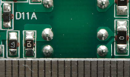
Near each usb connectors is a auto coding and over current protection IC (U7..U16: UC2501).
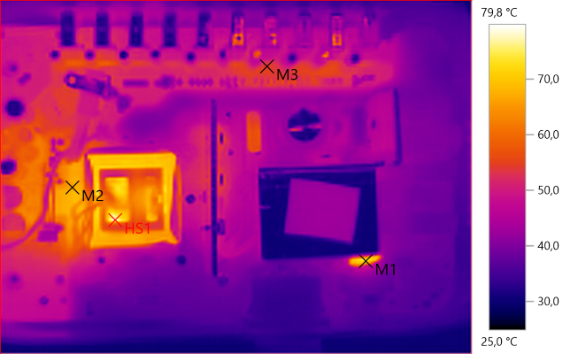
M1: 70,0°C, M2: 66,2°C, M3: 54,2°C, HS1: 79,8°C
A thermo look inside while it is running at full load. Temperatures is as expected, nothing is too hot.
M1 is the inrush current limiter that works as it is supposed to do, i.e. heat up and reduce resistance after the device is powered up.
Safety distance looks good.
Testing with 2830 volt and 4242 volt between mains and low volt side, did not show any safety problems.
Conclusion
This is a very impressive usb charger, it can charge 10 tablets or big smart phones at full speed, at least as much speed as you can get from "standard" usb charging without increasing or decreasing voltage. The auto coding secures as fast as possible charger for most devices. The top with slots for phones and tablets makes it possible to charge 10 devices without using a big table for the devices. The safety looks good, both isolation from mains voltage and individual port protection.
It is a good charger for schools, university and other places that need to charge many devices at once.
Notes
The charger was supplied by Ntonpower for review.
Index of all tested USB power supplies/chargers
Read more about how I test USB power supplies/charger
How does a usb charger work? The article is not valid for this charger.