Component testers
There are many different component testers on the market, some can test many different component for many parameters, other can only test a single type of component for a single parameter.
Usual the testers will use fairly low voltage and low current, this reduces the risk of damaging components, but it will also prevent the tester from detecting some types of components and measuring some parameters.
The name of the device will vary with is capabilities, i.e. "transistor tester" or "ESR tester" or many other names.
For testing I have mainly selected leaded components, because they are easier to connect.
Support equipment
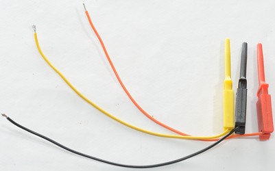
Because not all testers includes wires I have made my own set. They are used when measuring resistors and capacitors in my boxes and when needed for other components. This means that any ESR value shown will be to high, due to the resistance in the leads.
Resistors
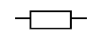
The European symbol for a resistor is a box.
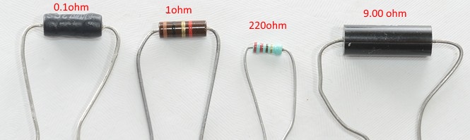
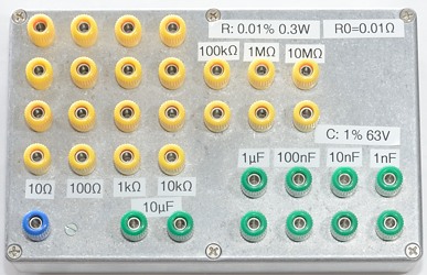
For this test I uses a set of 0.01% resistors mounted in a box and a couple of loose resistors.
For all resistors I have listed the resistance as measured by my Fluke 8846A, with the low values I have not used all four terminals on the box, but done four wire measurement to one set of terminals, this makes the 10 ohm resistor about 0.01 ohm to high.
I do also include a measurement with shorted test leads. When using the above test leads it will be way to high.
Capacitors
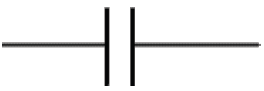
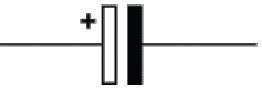
The capacitor symbol, the second symbol is used when the capacitor is polarized, but a component tester will not know that and usual uses a low enough voltage to not damage the polarized capacitors.
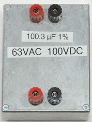
Again I uses my box with precision components, but this time they are only 1%. Generally it is difficult to get high precision capacitors, one reason is that capacitors can change value with frequency.
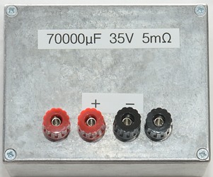
This box contains a lot of capacitors in parallel with a total value about 70000 uF.
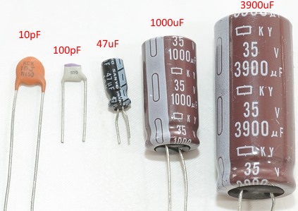
I do supplement with a few loose capacitors.
With capacitors the main value is the capacitance, but with larger capacitors the ESR (equivalent series resistance) is also a very useful value to know.
Inductors
A inductor is just some wire that is coiled, maybe with some metal in the middle.
The value will always be frequency depend, how much depends on the core (i.e. the metal in the middle).
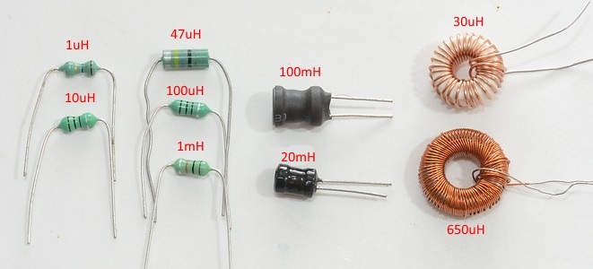
For testing I uses a couple of different inductor types.
The main value is inductance, but the resistance is often also important. Some testers may show small inductors as resistor with inductance.
Diodes
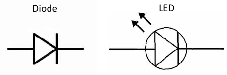
This is the simplest of semiconductor, but there exist many different types.
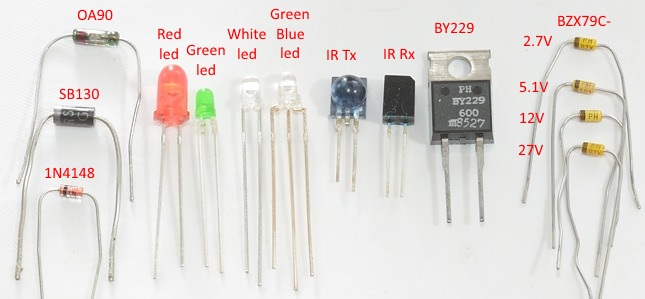
I have only included the most common diode types and a old germanium diode.
Depending on test voltage, it might be possible to detect zener diodes.
SCR (Thyristors) + Triacs
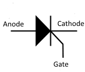
SCR is a controlled diode, it will start working as a diode when it gets a pulse on the gate, when current drops to zero it will turn off again. This is very useful for controlling AC. The pulse to trigger a SCR or triac can be fairly high, this prevents testers with low current from detecting them.
The pins are:
- A: Anode
- G: Gate
- C: Cathode
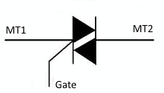
A triac is basically two SCR build together, it will conduct either way when it gets a pulse on the gate and will turn off again when the current drops to zero. The pulse to turn a triac on is not the same in either direction, this means that some testers will see it as a SCR.
A triac does not really have a anode and cathode because both pins are both anode and cathode.
The pins are:
- MT1: Main terminal 1
- G: Gate
- MT2: Main terminal 2
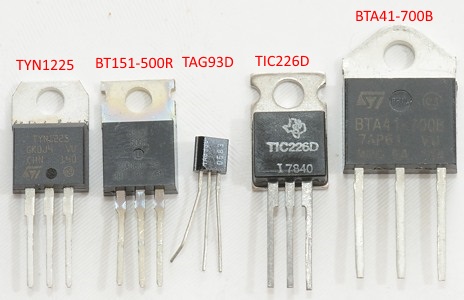
SCR and Triacs exist in many sizes, none of the testers can handle the big types, but some of the testers can handle the small types. The types in my test set are only smaller types.
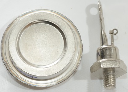
Some of the larger types looks this way, but there are other shapes to. These types may require 1A or more to trigger.
BJT (Bipolar junction transistors)
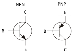
This is the simple transistor symbol, but not all transistors are that simple.
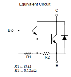
This transistor has two transistor inside (Darlington), some resistors and a diode.
The resistors will spoil any beta (hfe/gain) measurements, especially at the low current that is used in transistor testers.
The pins are:
- C: Collector
- B: Basic
- E: Emitter
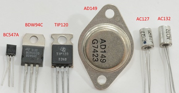
I have only included a fairly limited test set. But it do include NPN, PNP, silicium, germanium, darlington, small signal and power transistors.
FET (Field effect transistors)
These transistors exist in two main categories:
Junction FET: The input (gate) is a diode in the blocking direction.
Metal Oxide Semiconductor (MOS) FET: The input (Gate) is a capacitor.
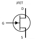
The JFET is on when the gate has 0 volt input.

The most common MOSFET transistors is the "enhanced" type, this means that they will be turned off when gate is at 0 volt.
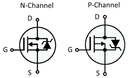
But there do also exist "depletion" types that requires a negate gate voltage to turn off (Like JFET).
The pins are:
- S: Source
- G: Gate
- D: Drain
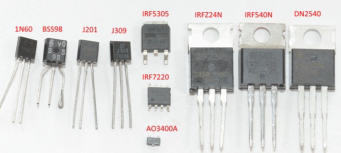
I have tried to include a bit of everything in the test set. I.e. both JFET and MOSFET in enhanced and depletion types.
IGBT (Insulated gate bipolar transistor)
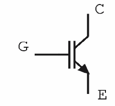
This component is a mix between a BJT and a FET transistor, this can also be seen in the symbol.
It has the simple voltage controlled input of a MOSFET transistor and the output stage of a BJT. When a combination of high current and high voltage has to be switched this is better than both BJT and FET transistors.
The pins are:
- C: Collector
- G: Gate
- E: Emitter
I have only included one.
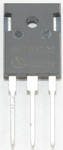
Voltage regulators
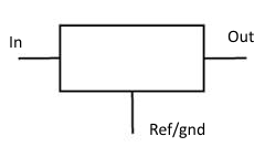
Some of the testers can also handle voltage regulators, but usual within a fairly limited range.
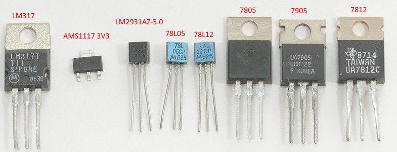
I have included a couple of different types.
Technical details
This chapter will list some technical details. This can be current consumption and what voltage it applies to the components it tests.