AC switch for multimeter test
This is not a review or building instruction, but a history about how and why I made a piece of test gear for my multimeter tests.
I wanted to test how fast the continuity was on multimeters and the usual fast test done by scratching the probe pins against each other was not good enough for me. It might look fine on a video and also gives an idea the speed of the meter, but I wanted a number.
My idea was to short the multimeter with a MOSFET transistor controlled by my AWG (Arbitrary waveform generator) and find the pulse width that exactly made the buzzer beep.
That was easily made. I put it in a small box with some gate protection and gate pull down on the MOSFET. It worked exactly as expected and I could also add a test on resistance with a 100ohm resistor. During these tests I found out that the timing on DMM's are not stable, the processor in the meter will sometimes have to do other jobs and may once in a while be slower on continuity. In my test I try to find the slow time, i.e. if the meter usual will detect a short in 5mS, but once in a while needs 50mS, I will say 50mS.
Later on I decided that I would also like to have some timing on capacitor, the large capacitors is usual easy enough to do manually, but a 10uF is hard to do precisely manually. The above method by pulsing it on/off would be very useful. This meant I needed something to switch AC, a mechanical relay could do it, but I wondered if it was possible to get opto MOSFET with this function.
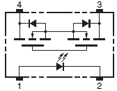
It was. I ordered 3 different types from Ebay, two arrived, one did never show up. Of the two that arrived one type had a on resistance of 30ohm (Datasheet says 1ohm), the other was fine.
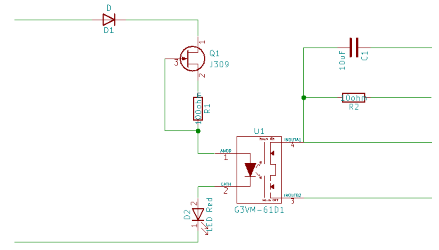
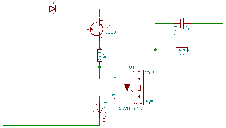
First I needed a schematic (That is useful if I ever need to look at it again), that did not take much time to draw (I cheated a bit with the opto switch symbol).
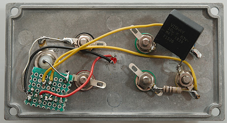
To make the switch mostly independent of input voltage and handle both + and - signals (I wanted to just put a square wave from my AWG into it), I uses a JFET as constant current source, this gives very low component count (An advantage for perf. board). I had a few JFET in stock, the best one was J309 with a resistor, it did not need much voltage to reach constant current and it stayed fairly constant. A diode to protect against the negative part of the square wave (A bridge would not work, it would double the frequency and I do not want that).
On my old switch I was also missing some indication saying when it was on, here I added a red led, I used red to get as low voltage drop as possible.
That means I had 4 parts to put on the perf. board, that was easy manageable, except the opto switch was a bit tedious because it was SMD (The two other I ordered was leaded).
The 100ohm resistor and the 10uF capacitor I planned on mounting directly between the terminals. For the capacitor I wanted a film capacitor, some DMM specifications warns against lower precision with electrolytic capacitors, probably due to the leakage.
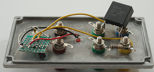
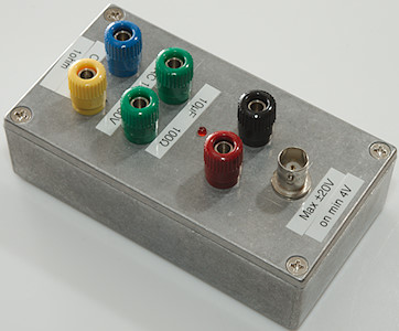
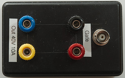
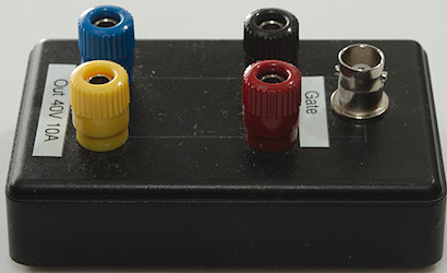
Everything mounted in a small box.
I could have used external resistor and capacitor, with my old box the resistor was external, but it is much faster just to move a banana plug to the next socket and I will always use the same capacitor and resistor for the test.
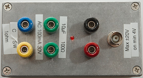
Some labeling on the box, including some specifications.
I have specified it lower than the switch is rated. The actual on resistance at 10V input from my AWG is not 1ohm but 0.65ohm and the switch is rated to 500mA 60V, the JFET is rated for 25V, but I do not need that and prefer not to do any repair on it at a later date.
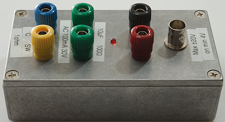
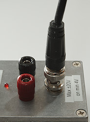
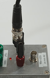
When connecting to my AWG I do not want to remove/mount the BNC to banana plug adapter, I made both types of sockets.
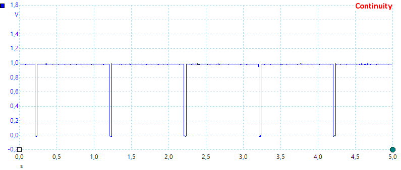
How is actual performance, here I test continuity on a multimeter, the multimeter uses 1V and once a second the switch will short the terminals. If the meter gives a beep each time my led flashes, the continuity can handle that pulse width.
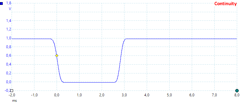
When doing this kind of measurement, it is also important how fast the switch is, data sheet says it can take up to 2ms to turn on. Here it looks like both on and off is below 0.5ms (Input pulse is 3ms). I do not expect to test lower than 5ms, i.e. the time is fine.
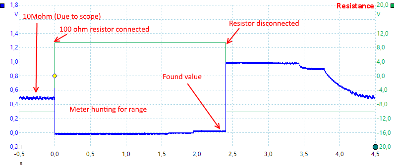
With ohm I can do exactly the same, but the timing is much slower and I have to watch the display for the 100ohm value.
Without a scope across the off resistance is in the Gohm range, i.e. meters will usual be in the OL state.
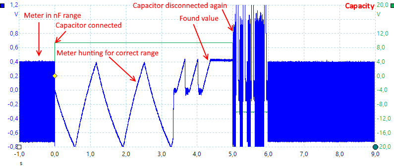
And with this switch the AC waveforms for capacity is no problem.
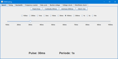
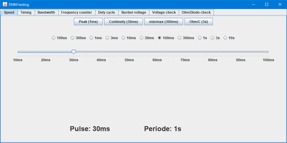
For each meter I test I need a couple of different configuration on my AWG and other equipment, after some time I got bored with always setting equipment up to different measurement and I made an application to do it. Above is the page I use for generating pulses for this box. The top is presets, next line is the ranges I need, then the slider to adjust the value and at the bottom the actual selected test values.
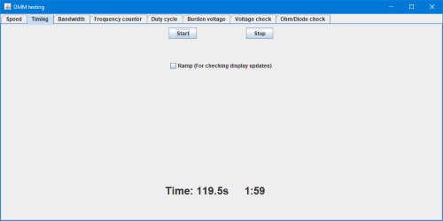
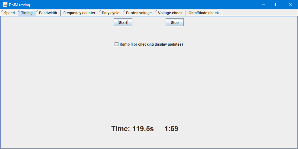
Testing large capacitors is timed manually, but now with the help of the box and the application. When I press start the large capacitor is connected to the meter through the box and then I press stop when the meter shows the correct value.
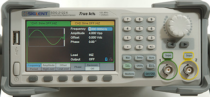
I am using this AWG for the testing, it fits nicely in the equipment stack on my main test station and it can do what I need.
Conclusion
As can be seen above I did not try to make a finished product, this is a one-off device for my testing.
Making this type of equipment makes my testing faster and more consistent.