How do I test internal resistance measurements
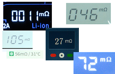
Some chargers can test the internal resistance of batteries, in my reviews I usual check how good that function is.
It is often a bit tricky because it requires a battery to work, a resistor or a power supply with a resistor will not do it.
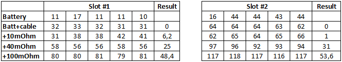
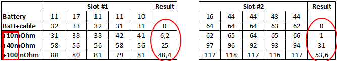
The final result looks like this with a schema for each slot. There will usually be separate schemas for LiIon and NiMH. This means I do about 200 manual measurement for a 4 slot LiIon/NiMH charger.
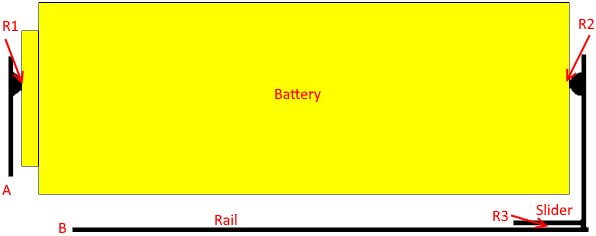
Here is a drawing of a typical charger slot. The internal circuit is connected to A and B and contains electronic to measure the resistance. There must, of course be a build in subtraction for the resistance in the rail and slider. It is fairly easy because it is constant. The trouble is the 3 places marked R1, R2 and R3, it is called contact resistance and the resistance will wary each time a battery is inserted. R3 can be improved if the slider is connected directly to B with a wire, instead of through the rail. R1 and R2 depends on the surface on the charger terminals and the surface of the battery terminals, cleaning terminals, high pressure or turning the battery may improve them, but there will always be variations.
The first measurement I do is put the battery in a slot and let the charger measure the internal resistance, I do this 5 times for each slot with the same battery for all slots.
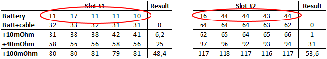
This is the first line in the schema. Any variation between values in each group of 5 values can be due to changes in contact resistance (R1..R3) or due to the circuit in the charger. If there are systematic differences between two slots, it will often be due to the circuit in the charger having small difference between the slots.
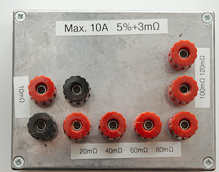
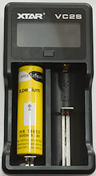
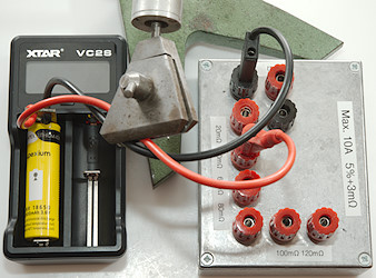
For the next part of the test I uses a resistor box with low value resistors and binding posts for connection, they give fairly constant resistance each time (Variation is only a few mOhm).
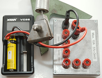
For this and the following tests I use a rig to clamp the wires to the charger to avoid any movement (This will change the contact resistance).
I connect and disconnect the red wire 5 times from the black binding post, this is my zero.
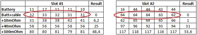
In this case battery, wires, connection has a total resistance of 32mOhm on slot #1 and 63mOhm on slot #2.
In the next couple of measurements the contact resistance is supposed to be constant (Within a few mOhm) and only variation is from the charger measuring circuit and from the different resistors.
Next I do 5 test in each of 10mOhm, 40mOhm and 100mOhm binding posts.
If at any time I move the wire to the charger I will probably have to start over.
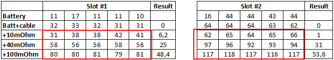
These measurements are filled into the table for the respective values.
The difference compared to the zero line is calculated in the result column, if everything is perfect it will be about the same value as the resistors.
If each line is fairly constant the measuring circuit in the charger gives stable results.
If the result column is close to the resistor values it is a precise measurement.
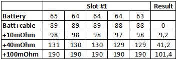
This table is not from a charger, but done with a high precision multimeter and shows how much precision can be expected from my setup.