USB meter info
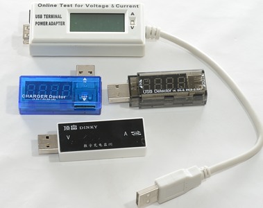
These meters are designed to put in between a usb power source and a usb device and will measure both current and voltage.
Some of the more advanced can also calculate power and add mA over time to get mAh.
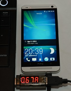
This can be very useful for checking usb devices and usb charger, i.e. can the charger deliver enough current and how much current does the device use.
What can I test in a review?
There is, of course, the precision of the two meters, but also how much does the usb meter affect the result. These meters will affect the result, sometimes only a little, other times significantly.
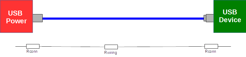
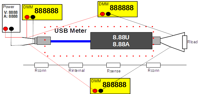
The usb connections we are measuring will be from a usb power source to a usb device, with a cable in between.
This connection will have some losses, both connections (Rconn) will have some resistance and the wiring will also have some resistance.
The connection resistance will depend on the quality of both connectors and how worn they are. For the cable it is the conductor thickness and length that affect the resistance.
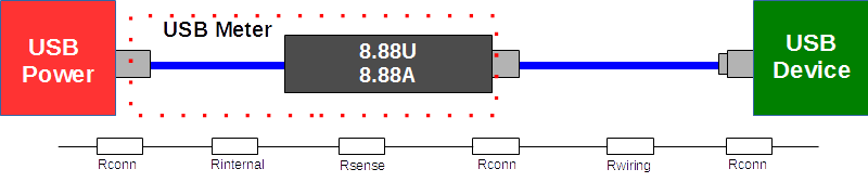
With the usb meter connected a couple more resistances are added, i.e. the loss from usb power to usb device will be greater.
There is one connector more.
Rinternal is the resistance from wires and connections inside the usb meter.
Rsense is the resistor used to measure the current (See below).
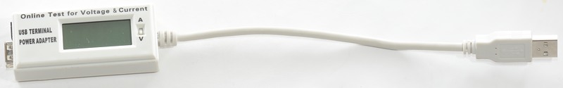
The above also tells us that this adapter starts with a handicap, with the long usb wire the Rinternal may be a bit on the high side.
For a minimal Rinternal this configuration is just about the best possible.
But there is still Rsense and Rconn that can affect the result.
When measuring I cannot get values for Rsense and Rinternal separate, I only get a total value and that value also includes two Rconn values.
If I open the device, it might be possible to read the value of Rsense from the sense resistor directly:
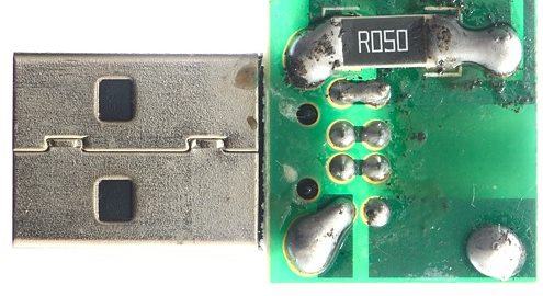
The R050 means 0.050 ohm or 50 milliOhm.
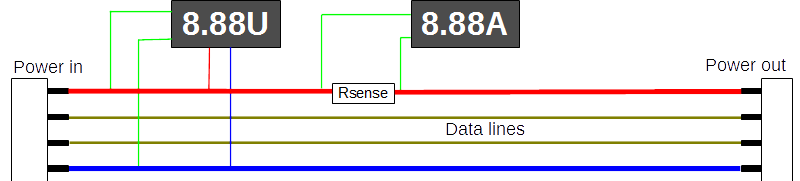
Here is the typical design of a usb meter. It will probably measure the voltage at the input, but if the input has a long wire (See usb meter above), then it will not be the actual voltage at the usb port, but a lower value.
Then it has the sense resistor and another voltmeter that measures the voltage accross that and shows it as ampere.
The measurement circuit and display will need some power, it will usual be drawn before the sense resistor and will not be included in the current shown on the display.
A USB connector is more than just power, it does also have two datalines, they will usual be routed straigh through and hopefully that routing is good enough to suppurt data transmission.
I will tests this with a memory stick, where I copy some data arround. This is not a very good test, but the best I can do.
Equipment used
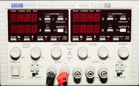
I need to vary the voltage and be able to supply current enough, for this I uses one of my high current power supplies.
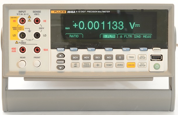
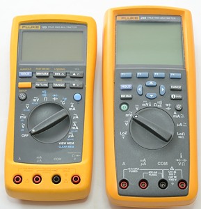
A couple off DMM's, one to measure the input voltage at the usb connector and two to measure the loss.
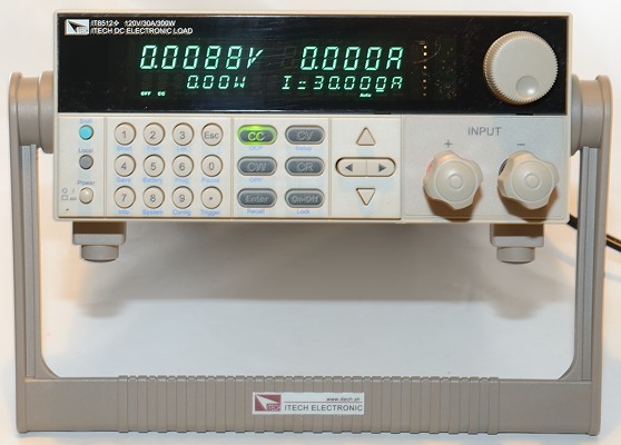
A electronic load makes it very easy to get a constant current load.
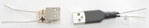
To eliminate as much wire (and resistance) as possible, I have made some usb connectors with thick wires out of them.
I only need thick wires until the DMM connections, outside that I could use thin wires.
Using DMM's accross the device, makes the measuring of the voltage drop more precise.
In the result I do not show the two voltage drops, but instead calculate the output voltage and the resistance of the adapter. Because the resistance includes two connections, it will not be very precise, but depend on how well the connectors mate.
I do also include thermo photos of the adapter to see how hot it gets. The temperature of the connectors will say something about how good connection they have (Low temp=good connection), but remember that the metal of the connector only works as a mirror.