Cable low resistance meter (milliohm meter)
I have for some time wanted to check cable resistance on mains leads. I could do it with my bench meters, but it requires some work to connect it each time and I do not want that work. My solution was to build a meter with a mains socket and some appliance inlet socket, I also added binding post for more versatility.
Contents
Requirements
Design
Circuit board
Enclosure
Battery power
Wiring up the meter
Software
Computer interface
Calibration procedure
Testing the meter
Using the meter
Measuring extension cords
Measuring a test lead, multimeter test lead and wires
Possible modifications
Change measurement current
Use another display
Add buttons
Add other connectors
What resistance to expect
Practical tests
Conclusion
Requirements
- Must easily measure 3 wires.
- Resolution in milliohm, i.e. 0.001ohm
- Range from 0ohm to above 10ohm.
- Precision better than 5%, but contact resistance is variable and will add a couple of milliohms.
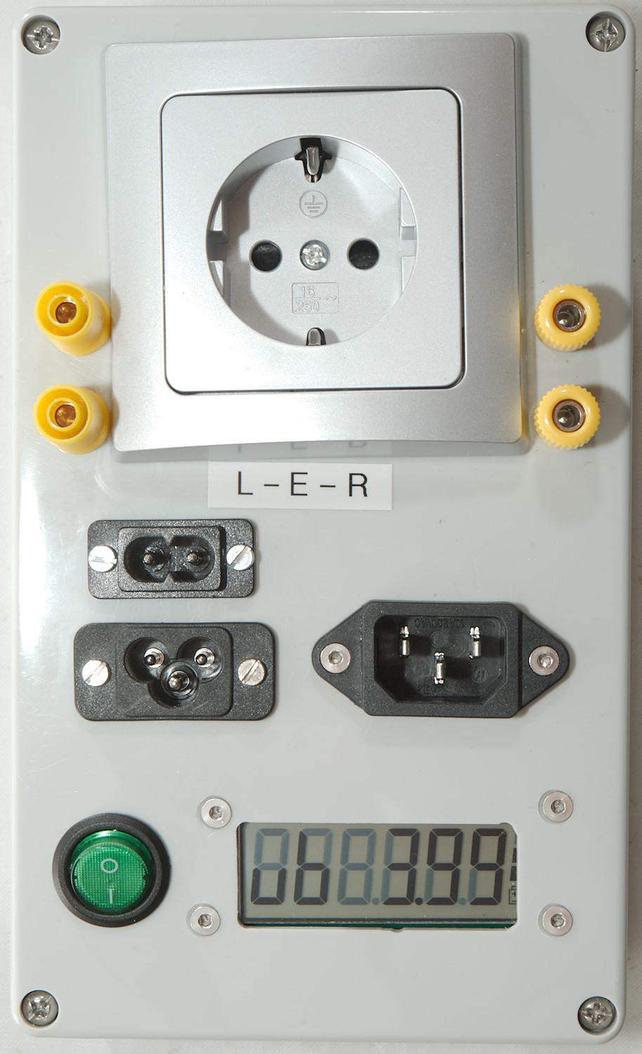
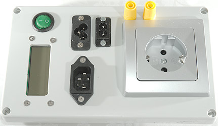
- Outlet must be EU type. I would have preferred a couple more, but due to space I only included this.
- Appliance inlet must be the 3 most common ones:
C5/C6:  C7/C8:
  C13/C14:
The plug is C5/C7/C13 and the socket is C6/C8/C14.
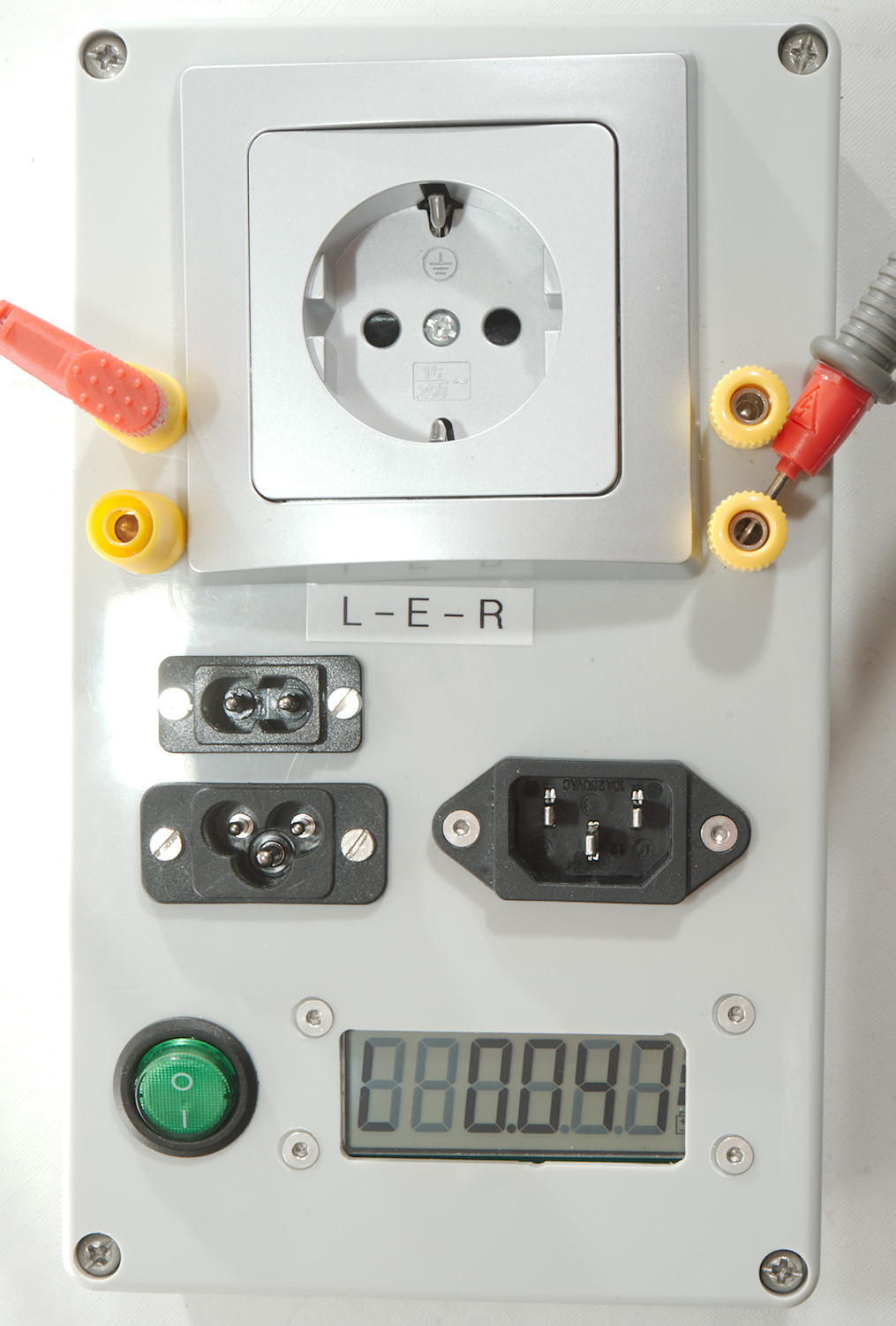
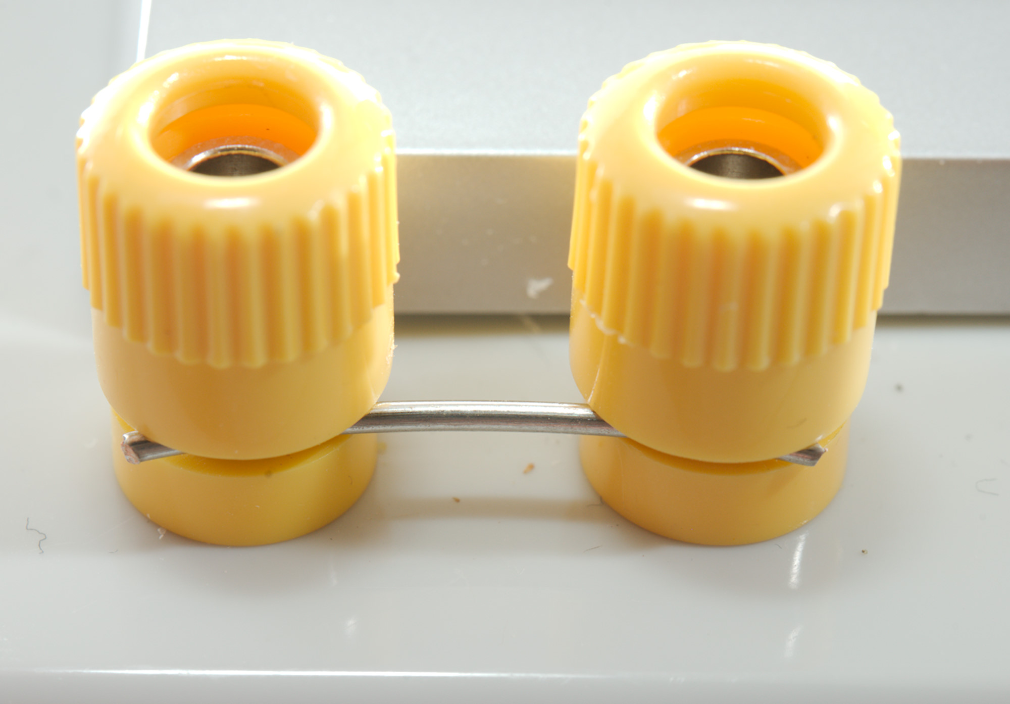
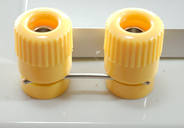
- In addition I added two 4mm shrouded sockets and two 4mm binding posts, this makes it easy to check test leads and multimeter probes.
- The binding post also makes it possible to check wires.
- Must be battery powered from a LiIon battery.
- Charging must be from USB.
Using standard outlets and inlets means I will not be doing 4 terminal measurements directly on the cable, my measurement will include the contact resistance and resistance in the socket.
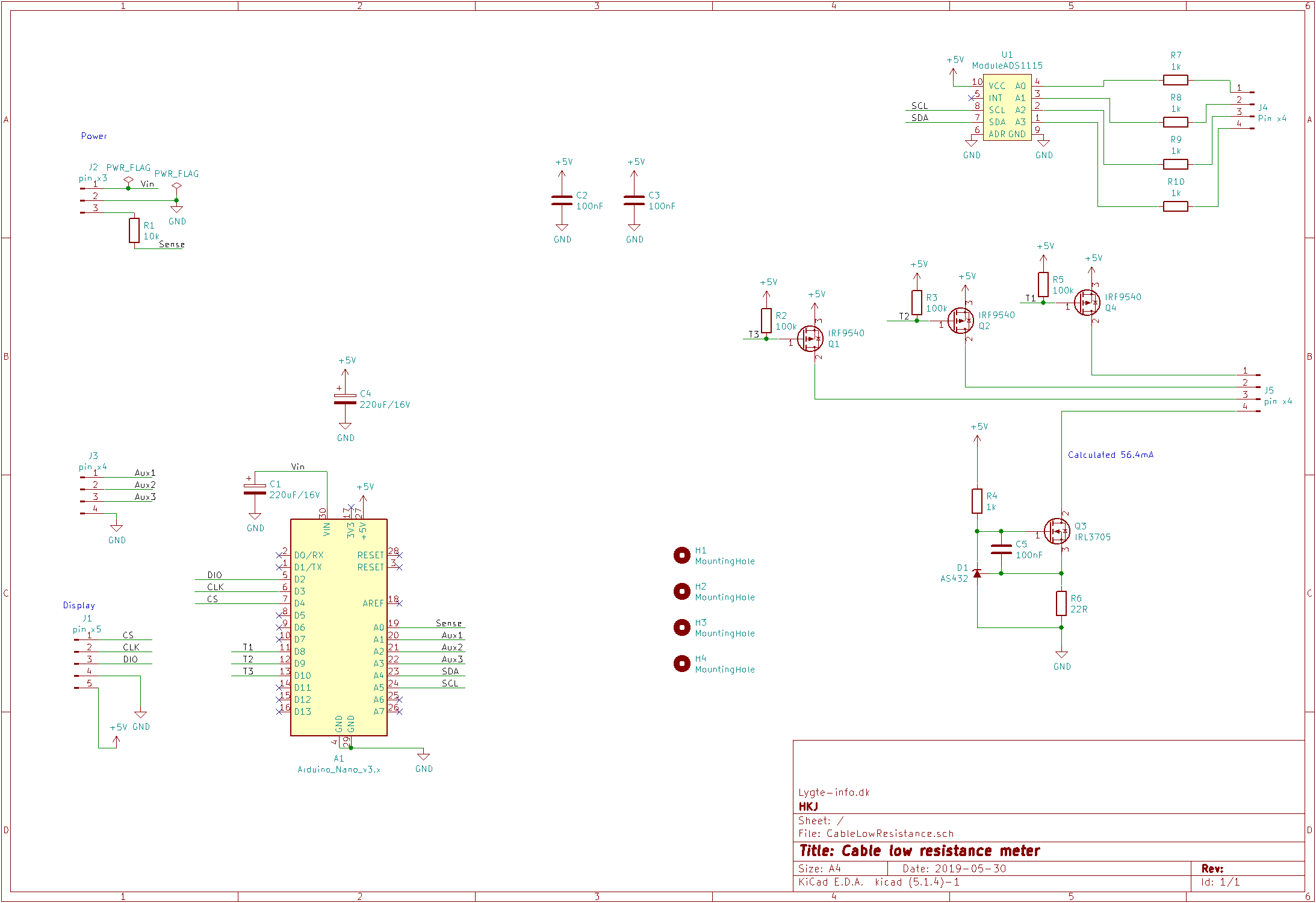
Design
There is two basic ways to measure resistance, either with a constant current source or with a reference resistor:
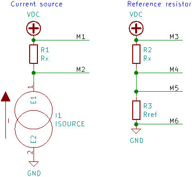
Multimeters often use the reference resistor, it requires two voltage measurements, one between M3 and M4 and one between M5 and M6 and then a few calculations to calculate Rx. The other method is to use a known constant current source, measure voltage between M1 and M2, then divide the result by the current to get the resistance. I wanted to use a 4 channel ADC and measure 3 resistors with it, they only way I could get this to work was with the current source. The final connection is not 4 terminal, but I wanted it 4 terminal to the back of the socket, this is fairly simple. I just have to place the voltage sense as close to the resistor (socket) as possible and not share any wires with the current source.
I did not want a accidental mains connection into one of the inlets to destroy the electronic, one way to do that would be with high input impedance and over voltage clamps for the ADC and fuses/PTC and over voltage clamps for the current generator, it is a lot of parts and I did not want to do that. Instead I shorted all the inlets and uses them as the common terminal, the connection is then switched at the mains outlet socket. This means a accidental connected mains wire will make some noise, sparks and blow a mains fuse and I may have to replace a inlet socket, but the electronic will not be damaged.
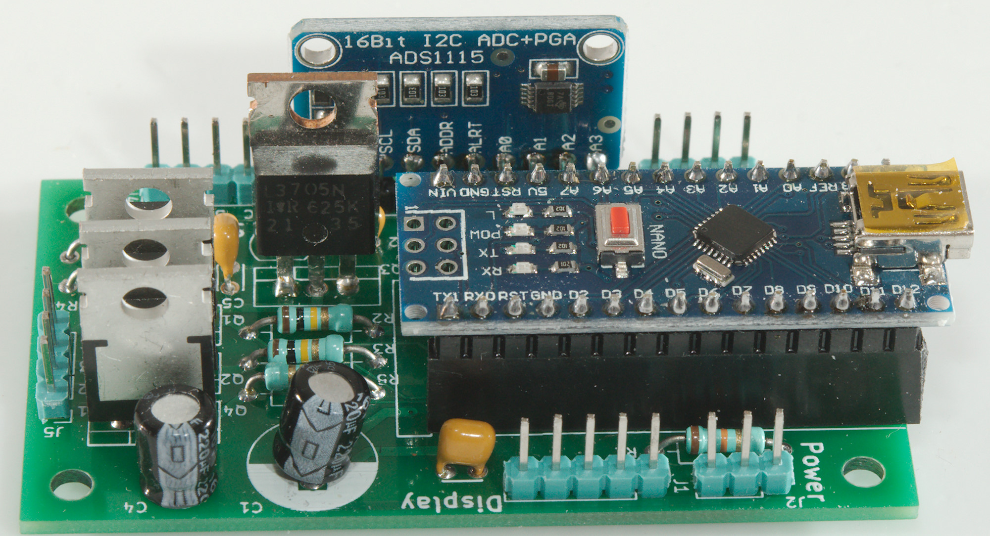
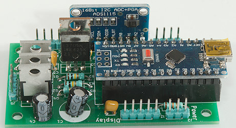
The final schematic is fairly simple. I use a Arduino Nano it is compact and I do not expect to use the USB connector much. The build-in ADC is not precise or sensitive enough, I use a ADS1115 converter/module. This converter is fairly slow, can handle fairly low voltage and is 15 bit*, the slow part is a advantage for me, because it will reduce the noise. To generate the current I need a stable voltage reference and a mosfet transistor. For the reference I use AS432, it is a 1.24V reference similar to the TL431 2.5V reference, but I wanted the lower voltage, this gives me higher gate voltage for the mosfet transistor and more voltage when measuring resistance i.e. I can measure slightly higher resistance with the same current. I could have added a higher range for the price of one current generator more (mosfet, resistor and reference), but I did not see any reason to do it.
The power connector has a sense terminal to measure battery voltage, this can easily be done by the ADC in the Arduino, it do not require very high precision. For the display I uses a 5 terminal header, this will work with just about any 7 segment display with a driver on, but because I use the voltage regulator on the Arduino I have to watch the power consumption. The AUX connector is for buttons, if I decides I need any.
The battery handling is not included, I will do that with external modules.
*It is announced as 16bit, but the last bit is sign and nobody calls a 2000 count multimeter 4000 count because it can show from -2000 to 2000.
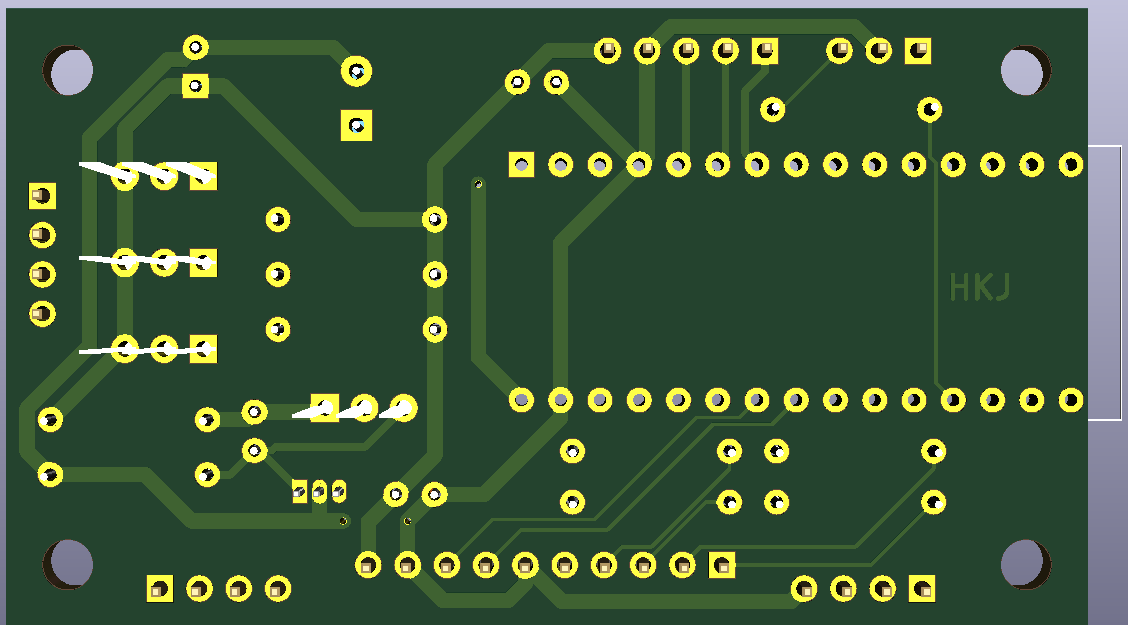
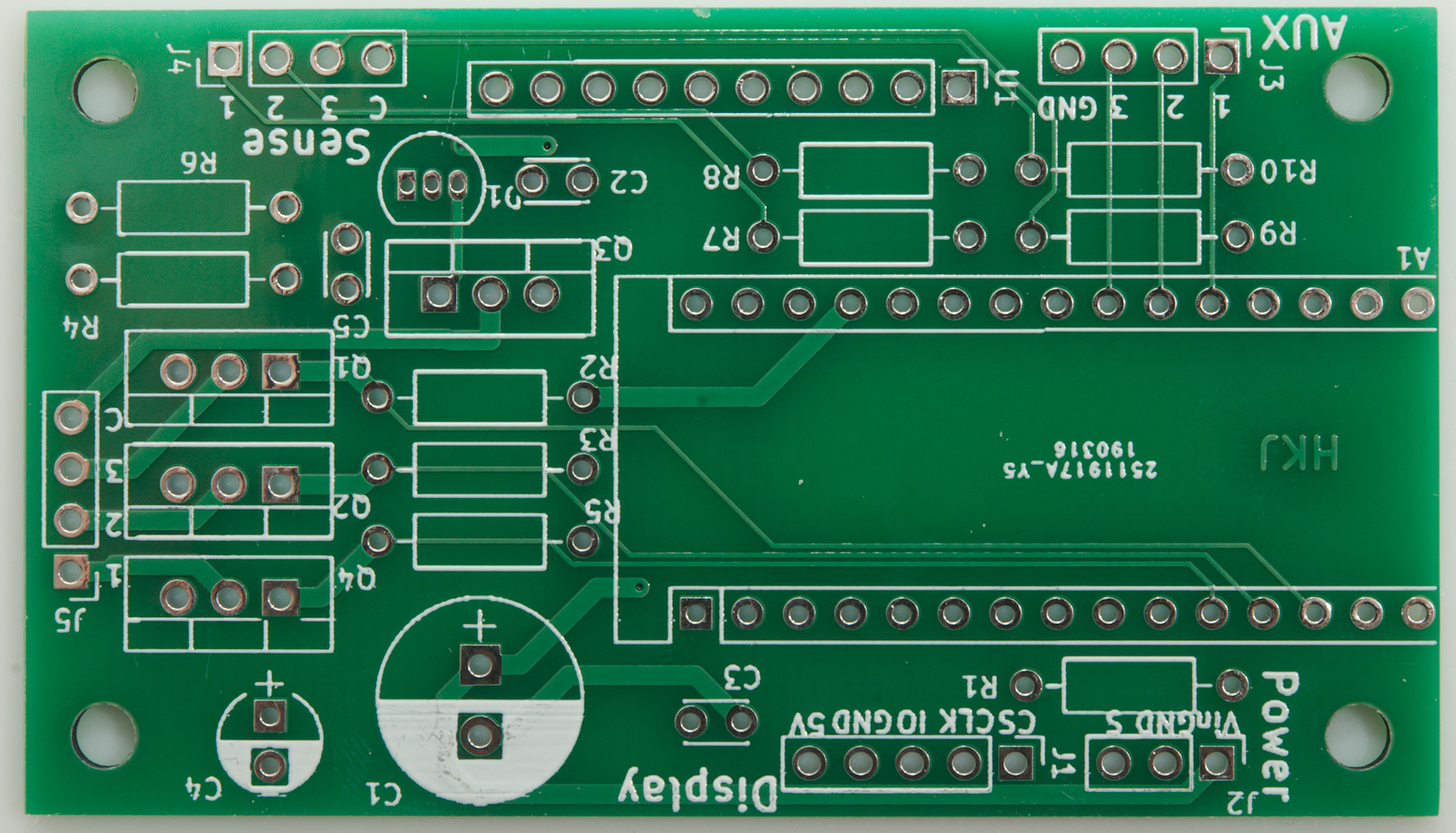
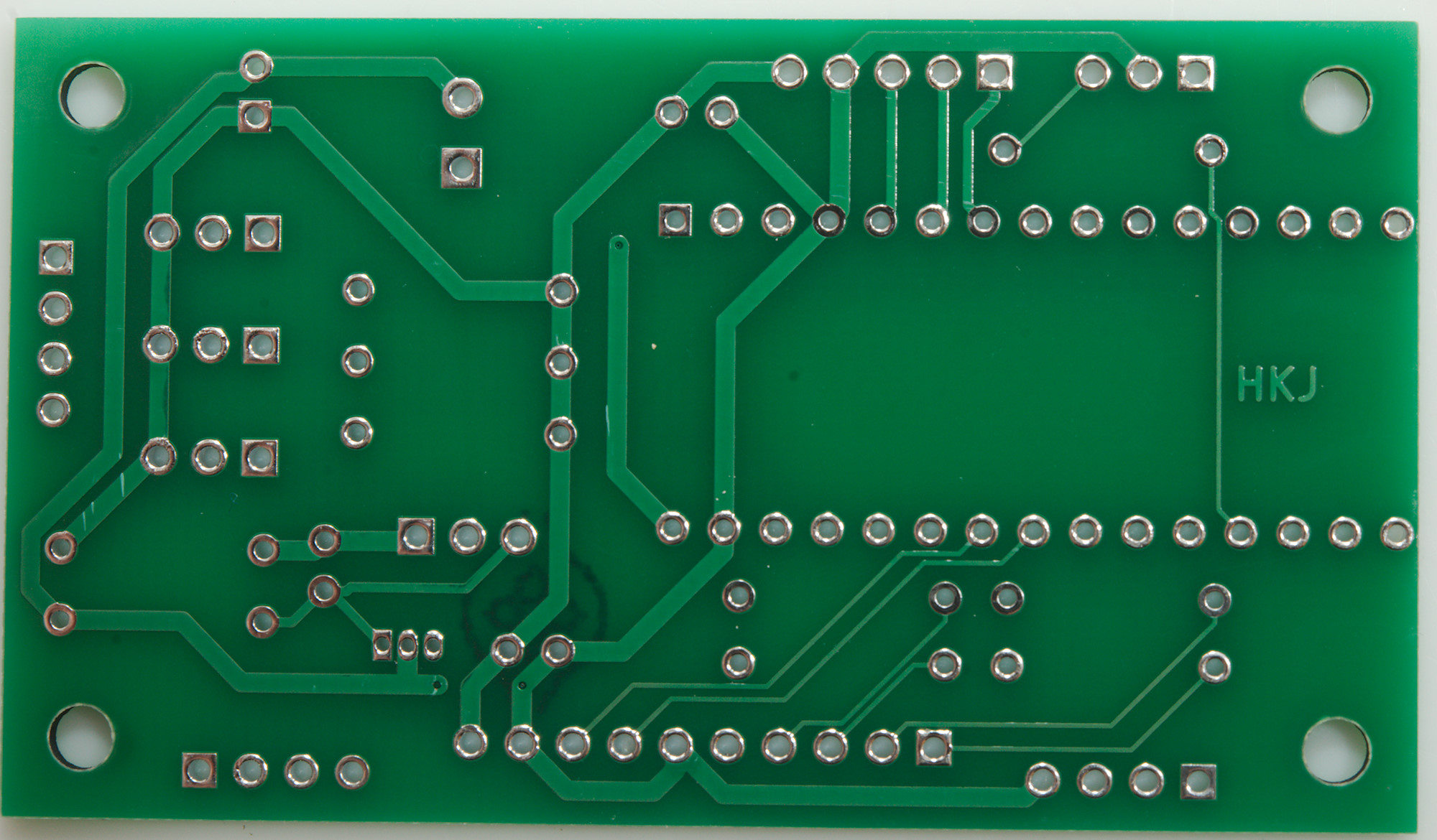
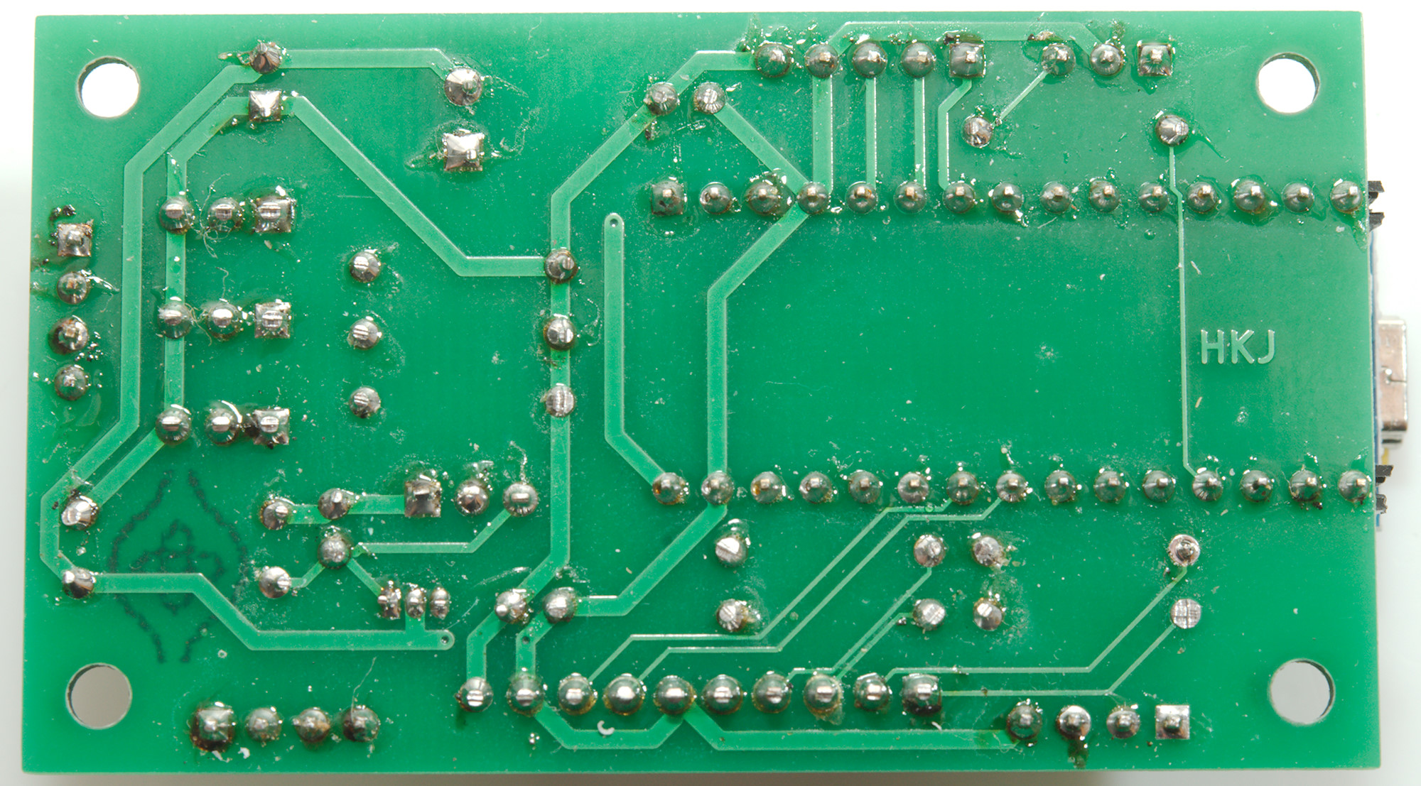
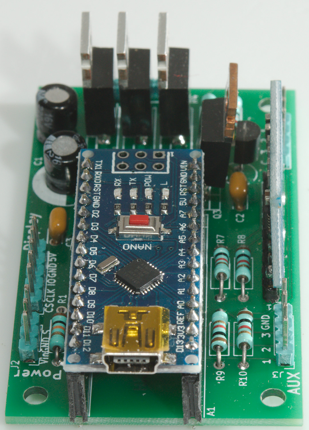
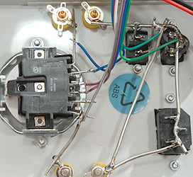
Circuit board
I did the PCB with all leaded parts, most of the space on the circuit board is used for the Arduino and the connectors anyway.
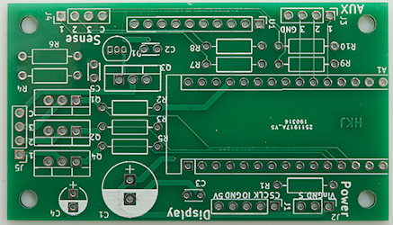
After some time I got the finished PCB. I can see one bug on it, C1 and C4 is the same size capacitor, but I uses different footprint for them.
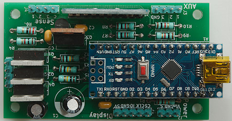
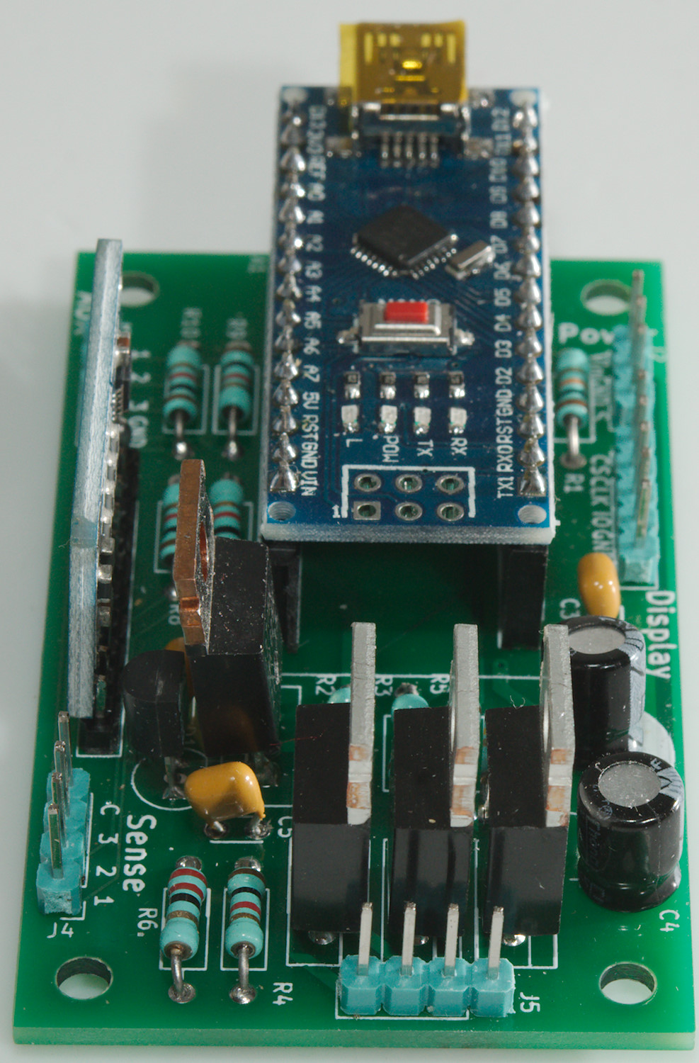
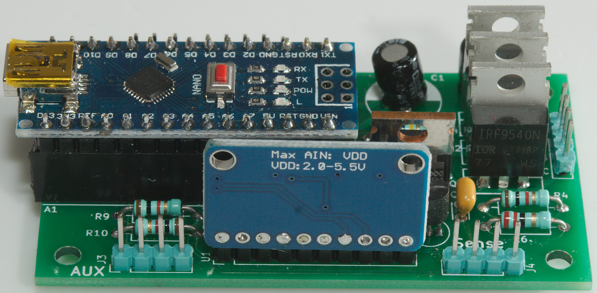
Here is is with the components and modules mounted.
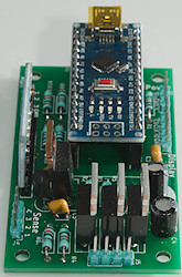

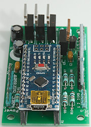
Looks from the sides.
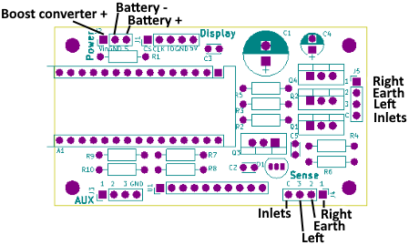
Connections to the PCB, I have left out the display connections.
The "Boost converter +" could also be connected to an external power supply.
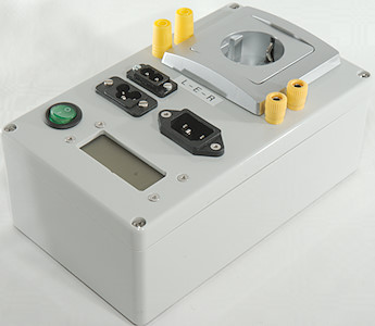
Enclosure
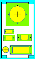
With a lot of stuff on the front and rectangular holes I need to do a bit of planning on how to place to parts. i did not include the binding posts in this drawing, they was first added later.
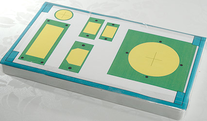
The drawing above was made in actual size and I could mount it on the lid.
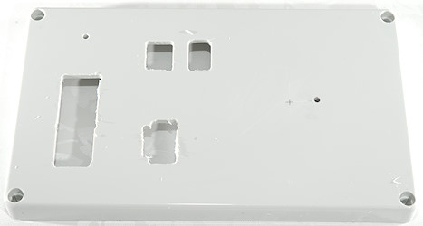
I only used it for rough cutouts for the rectangular holes and marking the center of the circular holes.
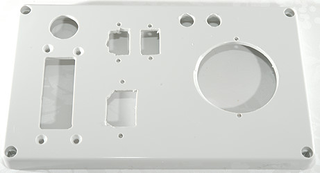
Some more work and all the holes are ready, including two extra. The cutouts are not very nicely done, but this is hidden when I put stuff in them.
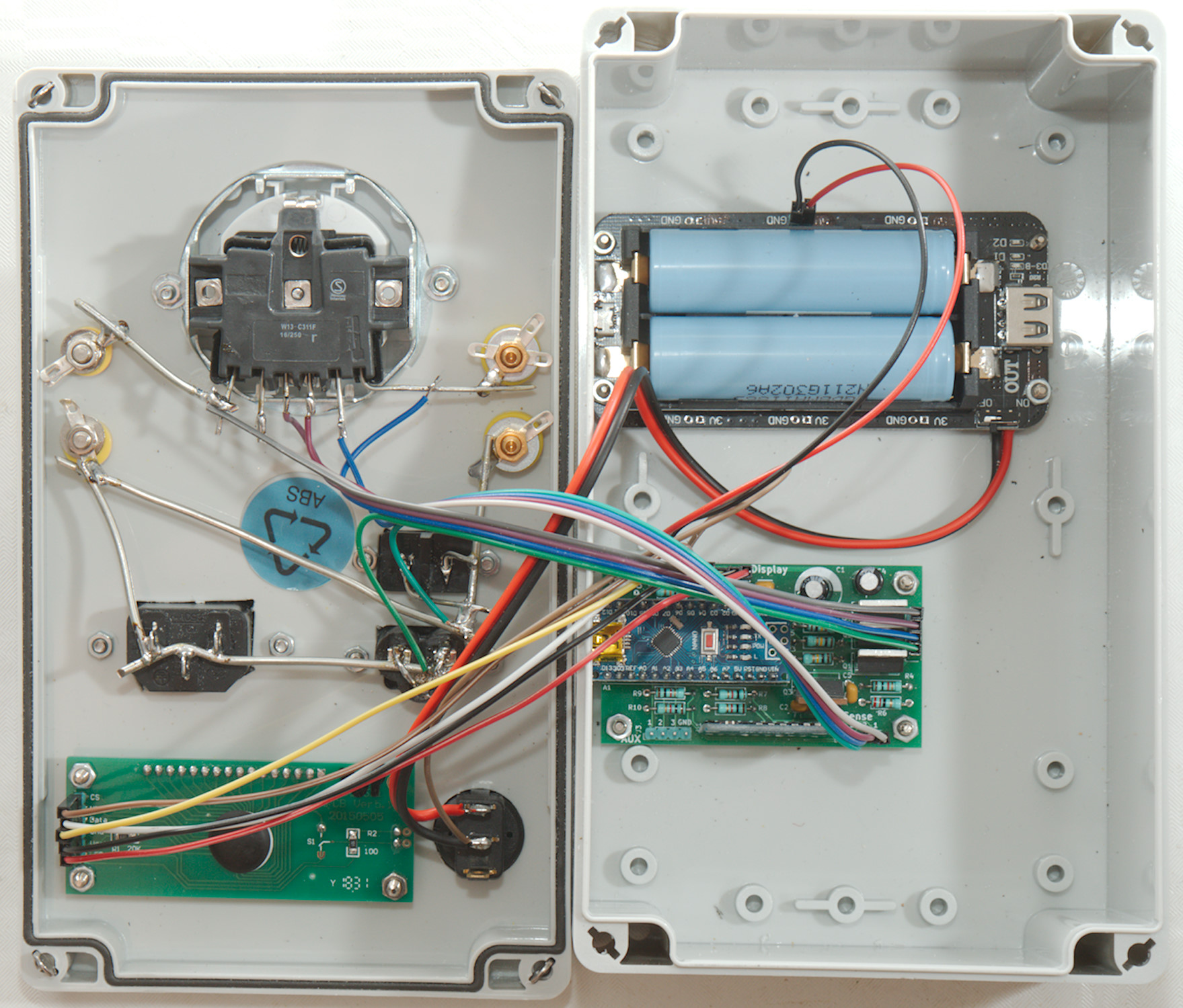
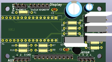
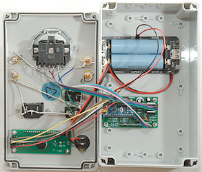
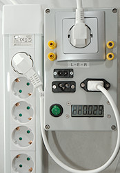
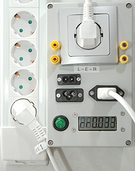
All the inlets, outlets, switch and display is mounted.
I could have used some black screws.
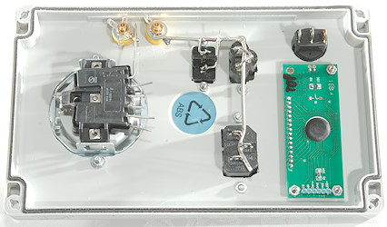
The low resistance connections are done, I used 14 SWG (ø2mm) for the thick connection (Below 1mOhm from end to end) and 18 SWG (ø1.2mm) for the rest.
The final result with shrouded connection to the left of the mains output and binding posts to the right.
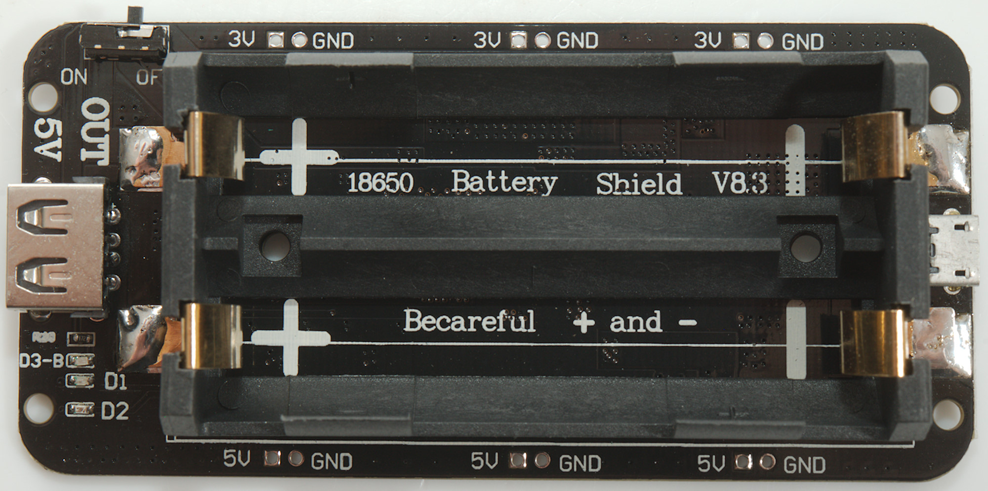
Battery power
I wanted to run the meter on batteries and at a voltage slightly above 5V to let the Arduino regulator smooth the voltage. The plan was to use a LiIon battery, a LiIon charging and protection module and a boost converter.
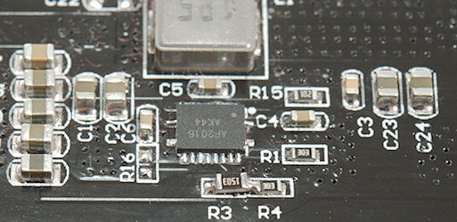
Then I saw this module with everything integrated:
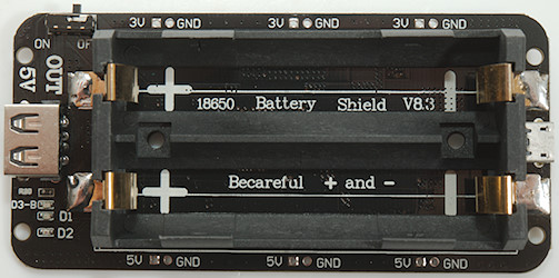
This module has space for two LiIon 18650 batteries in parallel, I only needed one, but with space for two batteries I used it.
The module has everything needed, except a voltage above 5V, the build in boost converter makes around 5.2V.
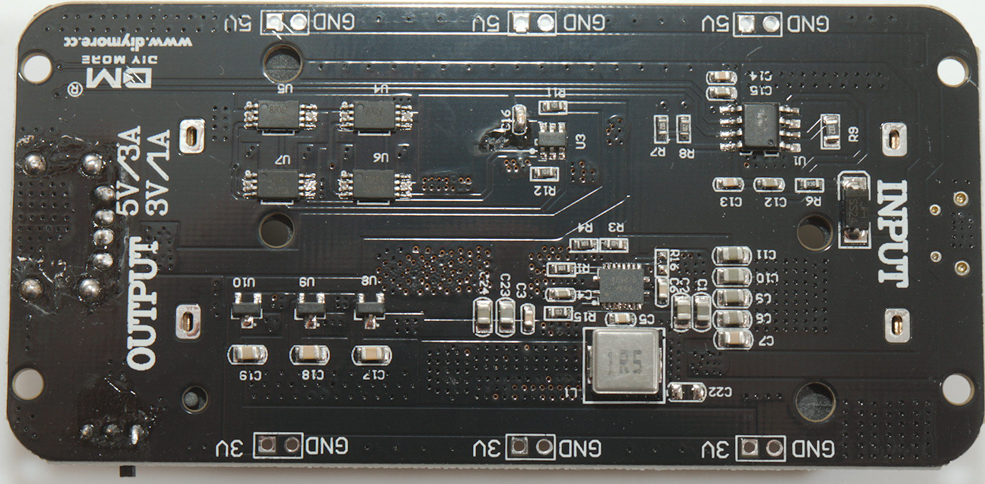
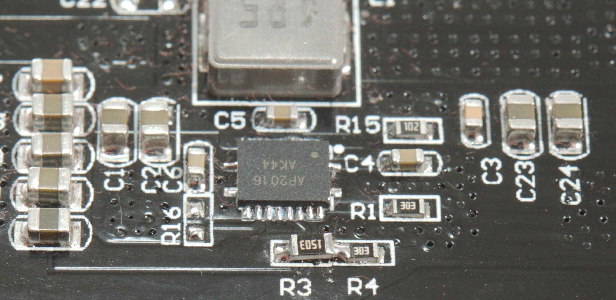
It was easy enough to identify the different sections on the circuit board and the boost converter was exactly as I had hoped with external divider to set the output voltage.
Replacing a 100kOhm resistor with a 150kOhm (R3) changed the output voltage to about 7.2V, exactly what I needed. I did not have small enough SMD resistors in stock, but the next size up worked fine.
I may be running the capacitors at over voltage, high capacity ceramic capacitors may be 6.3V, 10V, 16V or 25V. According to the schematic for the boost converter the output capacitors are supposed to be 1uF and 4x22uF, but here they are using 7 capacitors.
I have ordered some 10uF 25V 0805 for the future (Converter is only rated up to 12.6V, making it usable up to 12V output).
Wiring up the meter
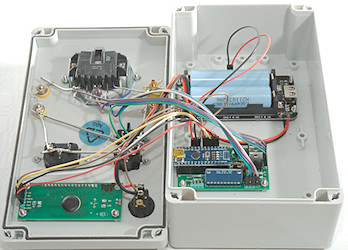
With everything mounted I had to wire up the connections.
The power switch is wired in parallel with the switch on the battery board and I added the voltage sense wire to the side that is turned off.
For the current source and voltage sense I used the same color on the source and sense connections.
My center point is the mains socket, it has two connections for each pin, I use one for source and one for sense, this way my reference point is inside the socket and after the connections. With the banana sockets the resistance I add is the thick wire from the source/sense connection (The closes one) and to the socket. With the thick copper wire I need more than 11cm for 1mOhm.
Software
The basic software is very simple, it needs to do these steps:
- Turn on current for selected channel
- Measure voltage across cable on selected channel
- Calculate resistance, i.e. divide voltage by reference current.
- Display resistance
- At fixed interval select next channel
This is what the software will do when running normally, but if it is connected to a computer I have added some testing and calibration options. The display can show resistance/voltage/current and it is possible to adjust the reference current value used for calculations to match the actual measured reference current.
I added some extra code to detect when no wires where connected to the measurement sockets and after a some time the display will switch to battery voltage. It will go back to resistance when any connection is detected.
If there is wires connected during power on it will read the resistance and store the values. These values are then subtracted from the readings, making the values relative.
For the display I uses my universal 7 segment library, this means that basically any 7 segment display can be used with the software. I select a 6 digit LCD display with battery indicators, if used with other displays this section will have to be commented out or removed.
For handling the analog input I use my ADS1115 library, it has a auto range function that does two conversion to get the best resolution, this means from 0.1V and up to Vcc I will get a resolution above 10000 count. This is also needed, a good cable may be 1mV. The converter has a resolution of about 8uV (0.008mV), this means the hardware resolution is around 0.15mOhm. I use a fairly slow conversion speed for best noise reduction.
The software is small enough that a Mega168 Nano can be used.
Computer interface
The Arduino program is not designed to be used from a computer, but as a standalone unit. This does not mean it is without computer interface, I used the USB connector for a test and calibration interface.
Commands:
- a: Select automatic scanning, this is the default. Can be used to cancel other commands (ler).
- l: Lock to the left channel.
- e: Lock to the earth/center channel.
- r: Lock to the right channel.
- o: Show ohms, this is the default.
- v: Show volt. High voltage means high resistance or open circuit.
- c: Show defined test current, this value must be calibrated to match actual test current.
- +: Increase defined test current, use 123 to select amount.
- -: Decrease defined test current, use 123 to select amount.
- 1: +/- will adjust defined test current with 0.01mA
- 2: +/- will adjust defined test current with 0.1mA
- 3: +/- will adjust defined test current with 1mA
- s: Save new calibration value.
Calibration procedure
- Connect supply voltage to the circuit.
- Connect USB socket to a computer.
- Use a terminal (Arduino serial monitor) for connection to USB serial port at 9600 baud.
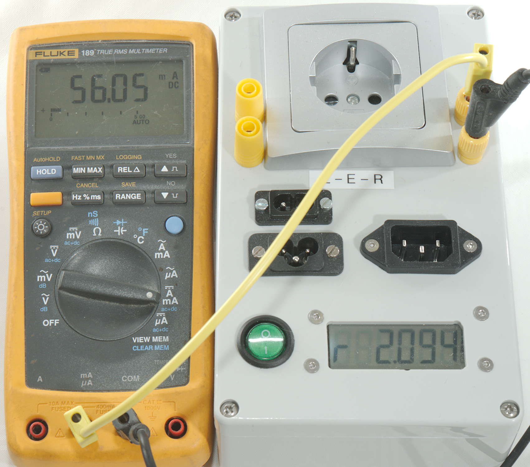
- Connect a ammeter between the outlet and a inlet, the meter must be in a range with maximum value of 60-100mA.
- Use ler commands to select the channel with the ammeter.
- Use c command to show calibration current.
- Use +/- and 123 command to adjust calibration current to match ammeter.
- Use s command to save new calibration and get back into normal mode.
- Calibration can be verified with a resistor (10-50ohm) between outlet and any inlet.
Note: In Arduino terminal it is usual necessary to press ENTER before the characters are transmitted to the Arduino. More than one character can be transmitted at a time.
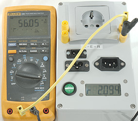
Connected to a ammeter.
Testing the meter
First test is power consumption
With 5V supply: 23mA without in idle and 80mA with a cable
With 6V supply: 36mA without in idle and 94mA with a cable
With 7V supply: 38mA without in idle and 96mA with a cable
With 9V supply: 38mA without in idle and 96mA with a cable
Internal 5V voltage with a cable (I.e. max. current draw):
With USB supply: 4.76V
With 5V supply: 3.87V
With 6V supply: 4.85V
With 6.5V supply: 4.99V
With 7V supply: 5.00V
With 9V supply: 5.00V
This means I have to supply 6.5V or more to get a stable 5V, the internal voltage regulator will have 0.15W power loss at 6.5V and 0.4W at 9V.
The changing power supply will not affect the precision of the ohm meter, only the battery gauge is affected.
Testing some resistors after the calibration procedure and using relative mode to cancel out the test cable:
10ohm (0.01%) -> Display 9.996
0.1ohm (0.1%) -> Display 0.099
0.2ohm (0.1%) -> Display 0.198
0.5ohm (0.1%) -> Display 0.496
1ohm (0.1%) -> Display 1.000
2ohm (0.1%) -> Display 2.002
5ohm (0.1%) -> Display 4.997
20ohm (0.1%) -> Display 19.99
50ohm (0.1%) -> Display 49.98
This shows it is fairly precise, the tolerances may be the used resistors and variation in contact resistance.
Using the meter
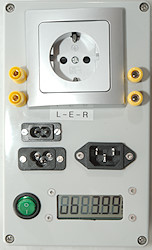
All values are in ohm, multiply by 1000 to get milliohm. The point will move right when measuring resistances above 9.999 ohm.


When no cable is connected the display will show ---- and change fast between the 3 different inputs.
The LCD display looks much better in real life than on these photos, due to the background light.


After some time it will change to the battery voltage. It will go back to showing LEr immediately when a cable is connected.
When only running on USB power, the battery voltage will show a very low value, because only the leak back through the converter will be present.


When a cable is connected the meter will usual show these 3 display, L is Left, E is earth, r is Right and then the resistance. Cables without earth connection will shortly show ---- for earth.
If a cable was connected between outlet and a inlet when turning power on it will switch to relative mode, this is shown by a r in the second digit. The relative value will only be stored for channels with a cable connected and only these channels will show the r.
With a computer connected there is a few other possibilities:


The display can be switches into volt mode, this will show a u in the second position. The first digit will show LEr.


When selecting calibration the reference current is shown.
These functions could be assigned to some buttons on the AUX connector, but I do not see any reason to do it.
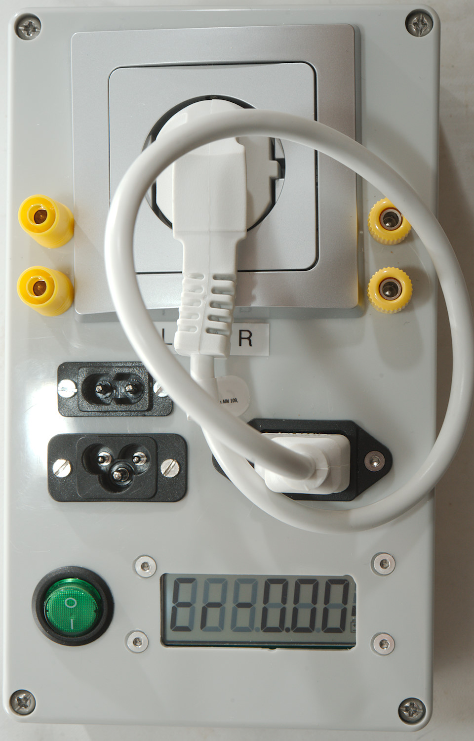
Measuring extension cords
To get a fairly precise resistance of a extension cord a good quality C13 lead is required.
- Plug the C13 lead into the unit.
- Turn the unit on or off and then on.
- Now the resistance of the C13 lead is stored as reference.
- The display will show the C13 lead as about 0 ohm (Negative value may occur).
- Connect the extension cord using the C13 lead
- The display will show the resistance of the extension cord, there must be a small r between the LEr and the value.
- Disconnect the leads and turn the unit off/on to clear the reference value.
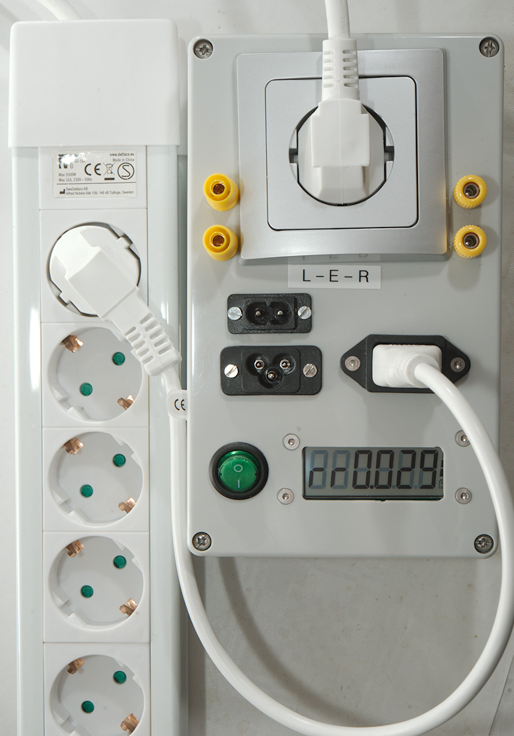
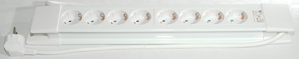
I checked both ends of the power strip, there as a small difference, the farthest end was about 4mOhm higher resistance.
Measuring a test lead, multimeter test lead and wires

The two extra sets of banana sockets makes it possible to measure test leads with 4mm banana plugs, both shrouded and not. Multimeter test leads and wires can also be measured.
A very short piece of SWG18 (ø1.2mm) wire, it is about 0.3mOhm, display shows 2mOhm. I decided to add a 2mOhm offset to the readings as a general connector compensation. This compensation is neither correct, nor wrong, but hopefully the result are slightly more precise.
Possible modifications
I am satisfied with the final unit, but it is possible to do some modifications while using the same circuit board:
Change measurement current
The current defines the resistance range it can measure. I uses 56mA, this allows from about 1mOhm to 60ohm with decent precision.
Increasing the current will improve the precision at low resistance values, but watch out for the voltage regulator on the Arduino, it must handle the current and heat. It can also be bypassed and a external 5V used, then Q3 may also need a heatsink.
Decreasing the current will allow measuring higher resistance values, but this may affect precision, the ADC can have down to 710kOhm (depends on range) in input impedance and that is in parallel with the measured resistance.
The current is defined by R6 and is calculated as Current=1.24/R6, I am using 22ohm: 1.24/22 -> 0.0563 -> 56.4mA. In reality the current was slightly lower.
Use another display
By changing the defines in "LEDDisplayDriver.h" it is possible to use many different displays, but my battery indicator is specific to the used display and must be removed or changed if another display is used.
By changing the code to display values more compact it is possible to use a 4 digit display and get 3 digits readout with 1mOhm resolution. This requires the use of "showNumWithPrefix" from the display library and means only one status character, i.e. the volt indication will not be possible.
With a LED display the regulator on the Arduino may get fairly hot, one way around this is to short Vin with 5V and use an external 5V supply.
Add buttons
I have not implemented any support for buttons, but uses the serial interface for commands, because I do not need to change anything during normal use. The AUX connector can be connected directly to buttons by using the internal pull-up. These buttons could be used for locking to a single channel, setting the relative values, showing voltage or even calibration.
Add other connectors
I wanted the meter for checking mains cables, but it can also be used for other types of cables, like USB, just mount some other connectors. The internal connection between the different connectors must be done with very thick wire or there will be a few mOhm error on some connectors. It is best to use high quality connectors to get as low contact resistance as possible.
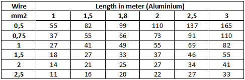
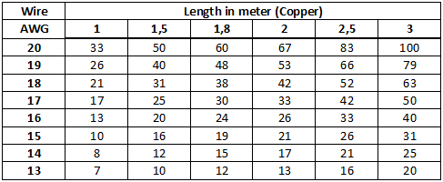
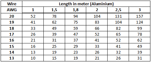
What resistance to expect
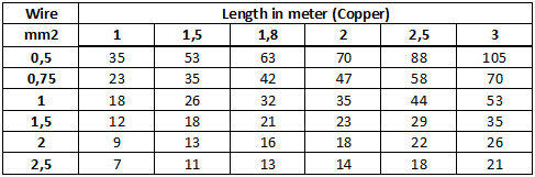
I have made some resistance tables below, all the values are in mOhm. For a good connection the contact and connector resistance may be below 5mOhm, but it can be up to 30mOhm or even higher for bad connectors.
A 1.8meter long 1.5mm2 copper cable is supposed to be around 21mOhm and with added contact resistance it must be below 51mOhm or 0.051 on the display.
Pulling the plug out and pushing it in again may lower the resistance because it will clean the connection, pushing it a bit around in the socket may also improve the connection. If there is a large difference between left and right, try turning the plug around. The difference is supposed to switch side.
What happens if the value is to high? The answer is usual nothing, the cable will work fine when used for low power devices. The problem is with high power devices, there the cable may get warm or even melt, this can be both a electric and a fire hazard. Really bad cables with many ohms resistance may also be very dangerous if the connected device shorts.
Cables with high resistance (Basically above 0.1ohm for these cables here) will not have any approval, except fakes ones.
Practical tests
I tested a couple of cables I had lying around and as can be seen in the table there is some bad cables.
C5: C7: C13:
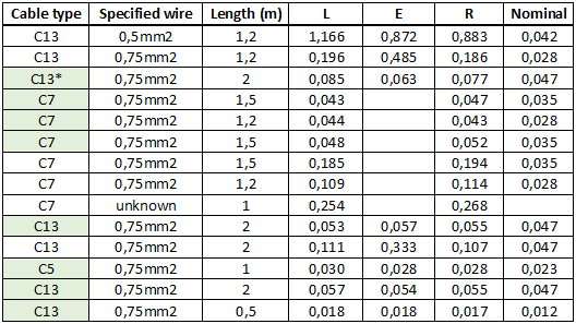
* Danish plug, using adapter to make it fit, this will add some resistance
The cables marked with green looks ok. The Nominal value is from the copper table above.
I also tried a power strip using the short C13 cable and relative mode. The cable on it is 1.5 meter long 1.5mm2, i.e. 0.018ohm
At the end where the mains input cable is the result was 0.025-0.025-0.026, at the other end 0.029-0.032-0.030. This varies slightly from my picture above, due to variation in connection resistance.
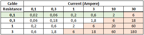
The above table shows the power loss for for a specific resistance and current, power loss is calculated for both wires and resistance is for one wire. The problem with high resistance is voltage drop and power loss. The power loss will heat or maybe melt the cable. The problems occurs when there is a loss of multiple watts in the cable (red area). Approved cables will be in the green area.
Conclusion
The meter is way better than initial requirement for 5% precision, but that is not always useful due to contact resistance. It is better than my 6½ digit meters for low resistance in 2 wire mode when doing some fast checks (The 6½ digit meter is more precise if I take the time to do a proper measurement).
This meter will be placed where I usual unpack stuff, this means I can check mains cables when I receive it, write the value down and then throw the cable into my cable pile as I have done before.
Notes and download
ACS1115 ADC library
Display driver project
Gerber files
KiCad project with schematic and PCB layout
Arduino project with libraries in same source folder